
TCBA Volume 3 - Issue 1
Page 8 of 18
Membership Activity
Eddy Aronson
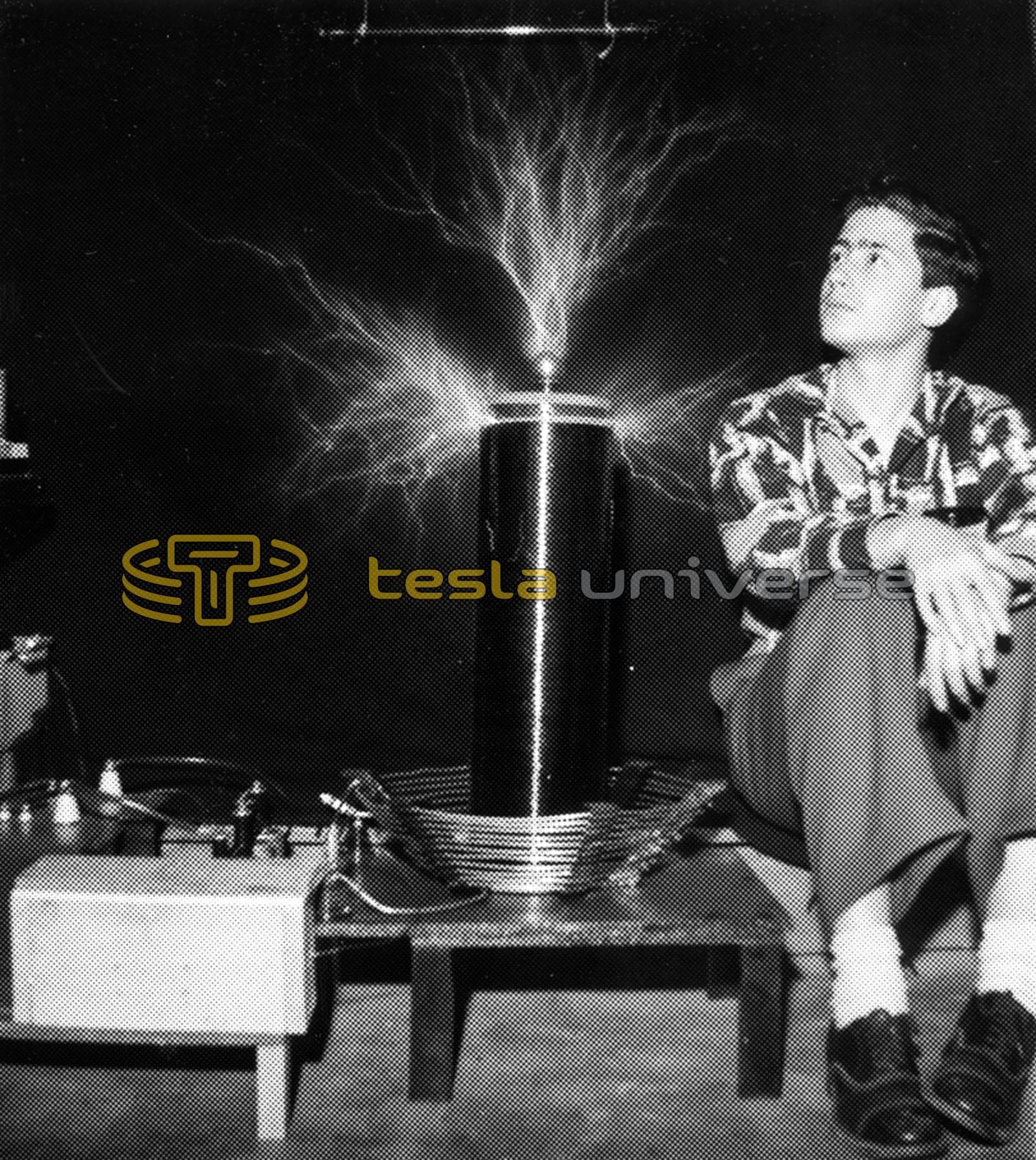
The double exposure photo at the right is of Eddy Aronson during his junior high school days. Ed is presently an aerospace electronics engineer at the famous Hughes plant in California. Like many electricians, Eddy got an early start by experimenting with electricity and radio. He is a licensed radio operator with call letters K2AKN.
It was inevitable that a youngster such as Ed would find his way to building a Tesla coil. Ed writes, “Back in my junior high days, I had one heck of a time finding any data on Tesla coils. The only information I could find was the basic circuit diagram. Another book stated that 'A Tesla coil is a transformer with a few turns on the primary and many turns on the secondary.'”
Ed continues, “My first coil was a flop - absolutely no output whatsoever. I tried several variations but all without success. A letter to the local General Electric Co. requesting help brought the following response.” 'Your coils are at right angles.' “I had no idea what they were talking about.”
“One day, I started to unwind my secondary. After the outer (fourth) layer was removed, I hooked it up and attempted to get a secondary output. No luck. I unwound the third layer and got the same results. However, things were different when I got down to the first layer of turns. Sparks began flying all over the unit (so that's the secret). I was so elated that I ran through the house yelling with joy. My parents thought I had gone bananas.
“The coil shown in the photo was my third project. Time (some 20+ years) has dimmed my recollection of the pertinent data on the project but I believe the secondary was close wound with #24 enamel wire on a cardboard form nearly 6" in diameter and 20 inches long. It was powered by two WWII surplus communications transformers (about $5 each from Radio Shack). That was back in the days when the firm was in the surplus business. The transformer primaries were wound for 90 volt inputs but I ran them on 115 volt house currents. The output of two in series must have been between 16,000 and 18,000 volts. They were not shunt wound so an inductance had to be installed in series with the primaries. The spark gap was a simple arrangement made out of two automobile spark plugs (aren't spark plugs for making sparks?) I don't recall what capacitance was used but the capacitors were oil filled surplus (also from Radio Shack) units.
“The coil gave a point-to-point spark of 20" in length. Take note of the interaction between the turns. That was the last time I used enamel insulated wire.
“Too bad there wasn't an organization like TCBA around in those days, it would have made things a lot easier.”