TCBA Volume 4 - Issue 1
Page 7 of 18
Membership Activity
Robert S. Hedin
3212 Skycroft Drive
Minneapolis, MN 55418
The cover photo for this issue features a neat Tesla coil project as built by Robert S. Hedin. This coil is unique in that the secondary can be adjusted vertically up and down as a means of varying the coupling.
The project is powered by a 6000 volt oil burner ignition transformer. The primary consists of 7.5 turns of 1/4" copper tubing and is 12" in diameter. The secondary is wound with approximately 400 close-wound turns of #26 enamel covered wire and is 6" in diameter.
Robert uses a commercial oil-filled capacitor rated at .01 Mfd at 12 Kv D.C. Take note of the neat little rotary gap. The rotor has 8 studs and is turned by a small shaded pole motor.
Lacking a sphere or toroid of sufficient size, Robert took the next step available to him by joining two 8" stainless steel mixing bowls to serve as the high voltage terminal. In its present state, the coil is capable of a 7"-8" spark. Robert hopes to improve on this by substituting a higher power supply and an improved secondary terminal capacitance.
Incidentally, Robert underwent surgery for a heart bypass this past autumn and is now getting back into experimenting. I am sure that he would be happy to hear from fellow Tesla coil experimenters.
Note!
Anyone who wishes to have their project featured in a future issue of the NEWS should send a good sharp and well lighted black and white photo of their project. Please include a detailed description of your project and include significant specifications. Coil size and spark length are not as important as the design and efficiency of the project.
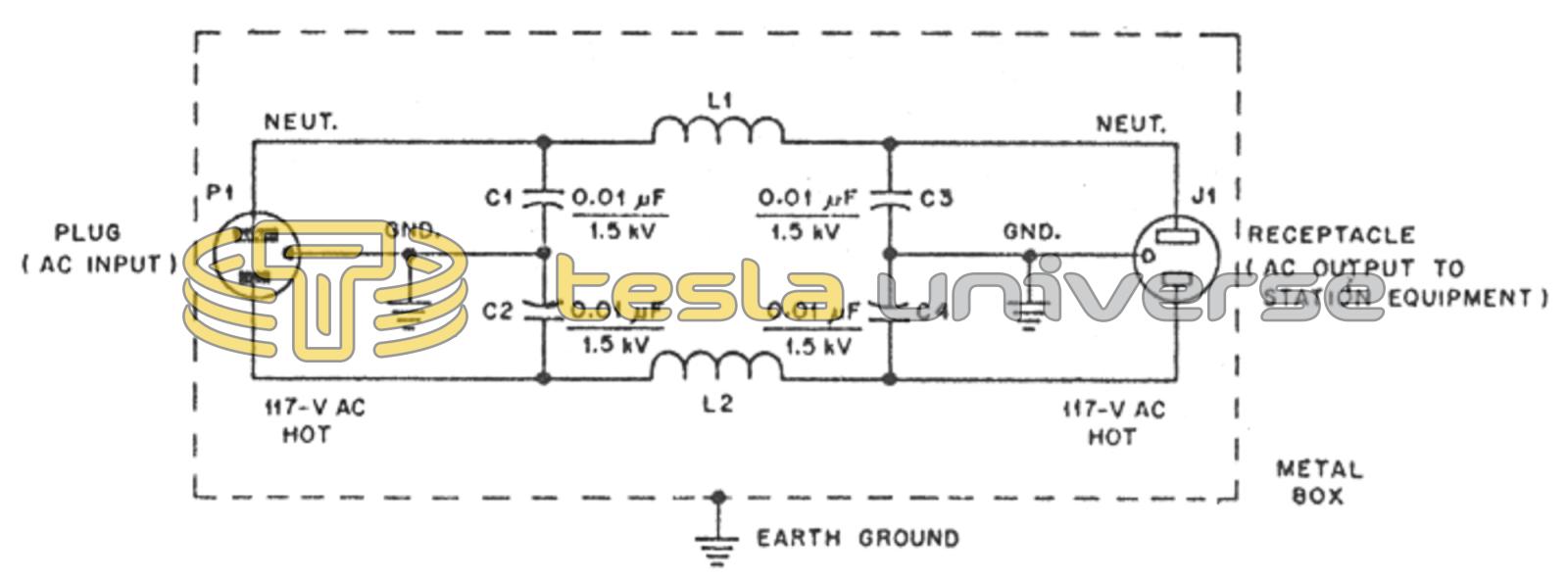
Need a Filter?
If your concerned with RF and TVI problems, you should realize that most interference by Tesla coil operation is the result of radio frequencies being fed back through the power lines. You can either buy a filter or build the one shown here taken from the July, 1984 issue of QST. This project should also help in quenching any kickback. TCBA wishes to thank member John H. Bielinski for the tip and also QST Editor Laird Campbell for permission to use this material.
A circuit you can duplicate is shown in Fig. 5. You may want to build this filter as your workshop project this month. The coils can be wound on hot/cold type PVC tubing. C1, C2, C3 and C4 are disc-ceramic capacitors with a 1.5-kV dc rating. Be sure to use heavy-gauge enameled wire for the coils. I suggest no. 14 wire for rigs under 150 W. No. 12 wire or larger should be used for greater amounts of ac power.
Warning: Do not plug the line filter into the ac outlet until the earth ground is attached to it. Without the ground connection you can get a mild shock if you touch ground and the filter box or equipment cabinets at the same time. Be sure to wire the plug and socket as shown (neutral, hot and ground connections). The filter should be installed as close to the station equipment as possible to prevent radiation of RF from the ac leads to the filter box.