Nikola Tesla Articles
Tesla Coil High Potential, Alternating E-field Electrostatic Charge Transfer
After reading Richard Hull and Scott Fusare’s article in ESJ 35, the author sought to clarify the conditions for charge transfer in terms of non-sparking and sparking Tesla coils.
The article, “A Close Look at Charge Deposition from a Pulsed Tesla Coil System,” by Richard Hull and Scott Fusare, ESJ 35, pp. 20-26, is a good piece of investigative research. In summary, it reported how a Keithley 610BR electrometer was giving a false indication of charge deposition on an isolated capacity from a Tesla coil system in which neither spark nor corona were created. I fully support the conclusions presented in the main article, which state that the tests must be conducted with a non-sparking Tesla coil. However, the statements regarding the operation of the Tesla coil in the last sidebar are vague, because they don’t make the distinction between sparking and non-sparking coils.
In the sidebar, entitled “Mea Culpa,” the statement, “no net charge is placed on remote conductors by a functioning Tesla coil,” is correct only in the context of non-sparking coils. Without this qualification, it implies that all functioning Tesla coils will not produce charge deposition on an isolated conductor. The majority of functioning Tesla coils are, in fact, intended to produce spark and corona. Thus, with a properly placed, isolated conductor, such as a sphere or toroid, located near the resonator top load but far enough away so that sparks rarely strike, charge deposition will be manifest on the isolated conductor.
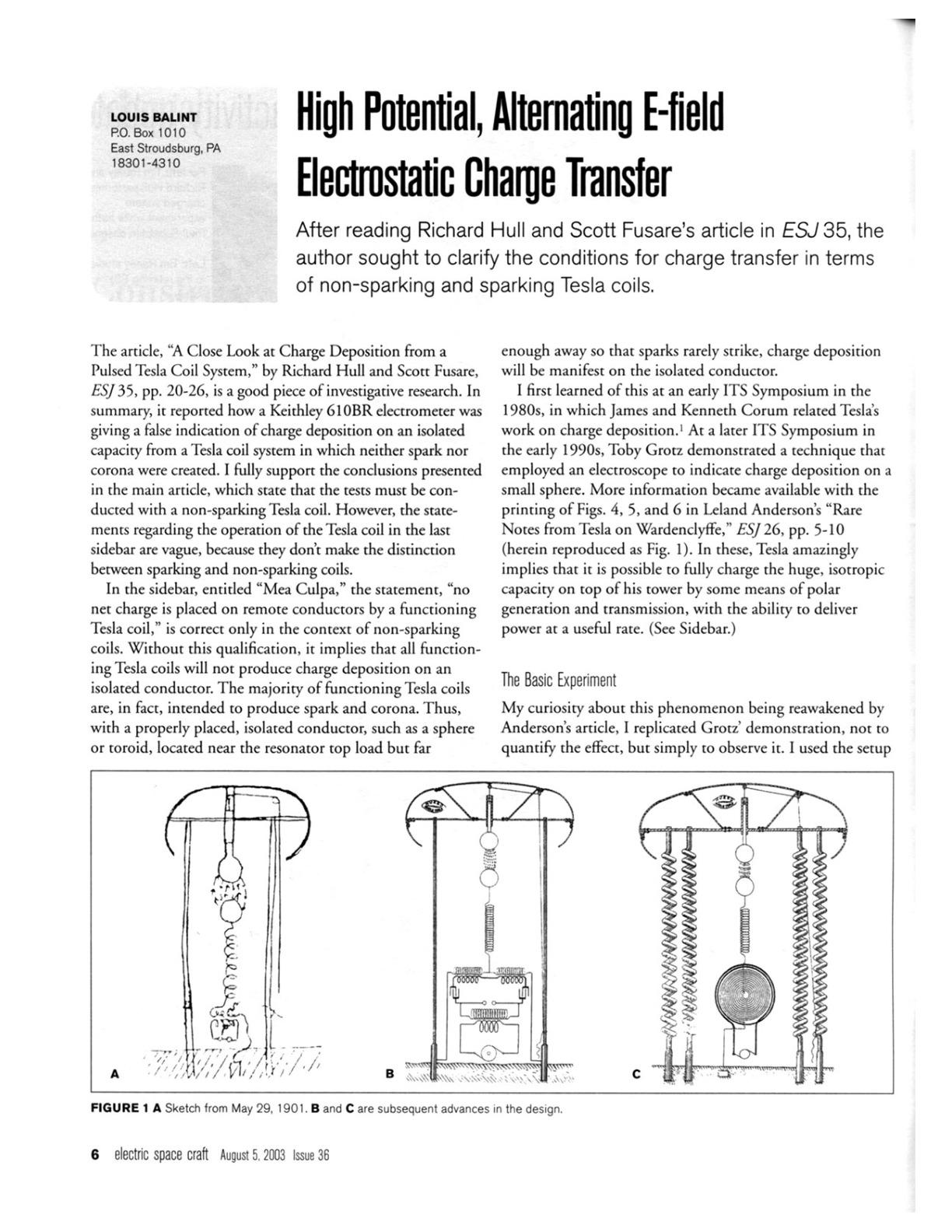
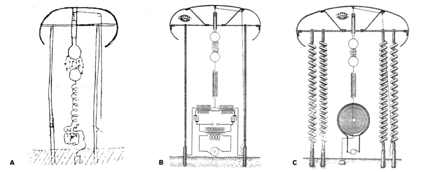
I first learned of this at an early ITS Symposium in the 1980s, in which James and Kenneth Corum related Tesla’s work on charge deposition.1 At a later ITS Symposium in the early 1990s, Toby Grotz demonstrated a technique that employed an electroscope to indicate charge deposition on a small sphere. More information became available with the printing of Figs. 4, 5, and 6 in Leland Anderson’s “Rare Notes from Tesla on Wardenclyffe,” ESJ 26, pp. 5-10 (herein reproduced as Fig. 1). In these, Tesla amazingly implies that it is possible to fully charge the huge, isotropic capacity on top of his tower by some means of polar generation and transmission, with the ability to deliver power at a useful rate. (See Sidebar.)
The Basic Experiment
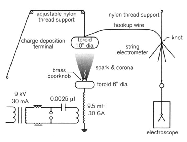
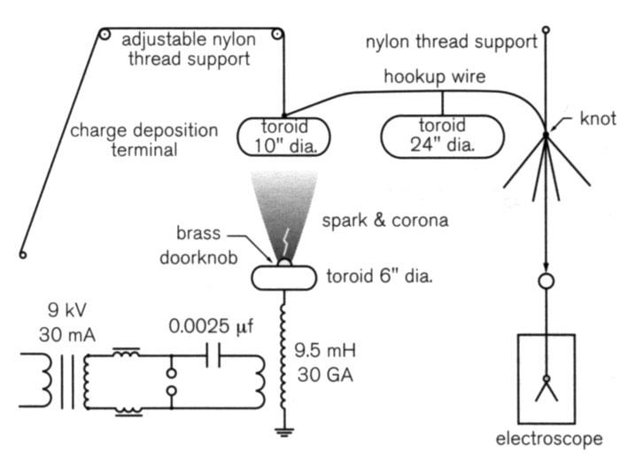
My curiosity about this phenomenon being reawakened by Anderson’s article, I replicated Grotz’ demonstration, not to quantify the effect, but simply to observe it. I used the setup shown in Fig. 2. The experiment was conducted a few years ago, shortly after I saw the article in ESJ, and was subsequently witnessed by John Freau. In preparing this article, I needed to refresh my memory of the finer details, so I reassembled my version of Grotz’ experiment as follows.
The Tesla coil used to generate sparks, shown in the diagram, was set up in the usual fashion. The spacing between electrodes within the series spark gap was minimized, and the number of gaps was limited in order to facilitate a high break rate. This also served as a safety measure, limiting the spark length. In addition, a small brass doorknob was placed on the axis and toward the top of the six-inch-diameter resonator toroid to direct sparks and corona upward, instead of radially from the toroid. Of course, the primary was tuned for maximum output.
A ten-inch-diameter toroid, suspended above the resonator terminal by means of a string and pulley attached to the ceiling, served as the charge deposition terminal. The electroscope, which used two strips of aluminum foil for the leaf indicator, was placed some distance away from the resonator setup, for obvious reasons. A length of insulated hookup wire, connected to the top, center of the suspended terminal, led away from the apparatus to a point above the electroscope. It was suspended by a nylon string attached to the ceiling. The wire was then vertically drawn down for connection to the electroscope terminal.
When power was applied to the luminous tube transformer of the resonator circuit, at about 80% of the input voltage, sparks easily emanated upward from the doorknob terminal within the resonator top load, toward the charge deposition terminal. The vertical spacing between the terminals was 24 inches, which was the maximum logistics allowed. With this setup, spark length did not exceed eight inches, and no electroscope activity was discernible.
Unexpected Electroscope Behavior
A series of tests was conducted with the charge deposition terminal lowered in increments until it was a little over nine inches above the doorknob terminal. This left more than an inch of space above the streamers, so sparks would only rarely strike the deposition terminal. With no power applied, the electroscope leaves hung idly, but when power was applied to the resonator, the leaves would slam together and hold until the power was withdrawn. Then, the leaves would move apart, and remain separated slightly from one another. If a grounded object touched the deposition terminal, a slight, static discharge was felt and heard, and the leaves of the electroscope would once again hang idly.
Puzzled as to why the leaves in the electroscope slammed and held together while the resonator was running, I tried another method of investigating static charging on the deposition terminal. I found a crude, but reliable means of indicating charge deposition: a nylon string.
Specifically, I connected the nylon string, used to suspend the hookup wire, to the ten-inch toroid. The nylon was allowed to hang freely about six inches beyond the knot which was tied to the insulated hookup wire. The string consisted of three twisted strands, which were unwound from one another, from the free end all the way to the knot at the hookup wire.
With no charge on the isolated, deposition terminal, still positioned above the resonator terminal, the loose strands hung against the vertical section of the suspended hookup wire. When power was applied, the electroscope behaved as before.
However, with charge accumulation on the deposition terminal, and static charge from the wire being induced on the strands of thread, the individual strands at the free, or lower, end of the string repulsed the hookup wire, and repelled one another. This phenomenon, similar to the way one’s hair stands up while touching the terminal of a Van de Graaff generator, is to a degree dependent upon the makeup and conditions of the experiment. Turning off the power to the resonator again caused the leaves of the electroscope to remain separated until the deposition terminal was discharged. As the leaves within the electroscope collapsed, so did the strands of the string.
Clearly, some form of charge deposition was at play here. But why was it that when the resonator was operating, the leaves of the electroscope were slamming together while the strands at the end of the nylon string, as expected, were moving away from one another? The basic laws of static electricity state that like charges repel and unlike charges attract. Could it be that, under the conditions of this setup, one electroscope leaf was maintaining a positive charge while the other leaf had a negative charge?
Tesla’s Method of Charge Conveyance
In articles Tesla wrote for various publications, and in quotes from newspaper interviews, he hinted about a method and a component for generating and transmitting polarized charge to the top of his tower. Following is a sampling of statements made by Tesla that are relevant to this subject. (Italics added.)
“In 1896, I brought out a new form of vacuum tube capable of being charged to any desired potential, and operated it with effective pressures of about 4,000,000 volts. I produced cathodic and other rays of transcending intensity. The effects, according to my view, were due to minute particles of matter carrying enormous electrical charges.
One of the first striking observations made with my tubes was that a purplish glow for several feet around the end of the tube was formed, and I readily ascertained that it was due to the escape of the charges of the particles as soon as they passed out into the air; for it was only in a nearly perfect vacuum that these charges could be confined to them.
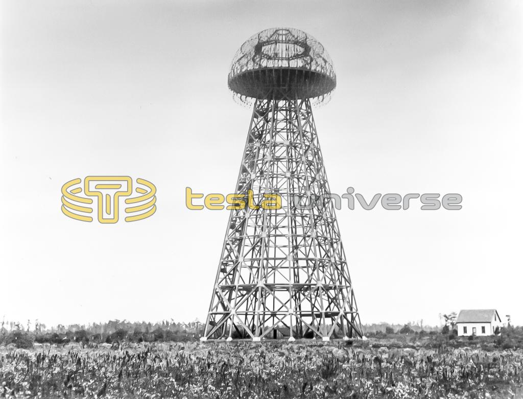
“Nikola Tesla Tells of New Radio Theories,” New York Herald Tribune, 22 September 1929, pp. 1, 29.“My wireless tower on Long Island, erected in 1902, carried a sphere which had a diameter of 67½ feet and was mounted in this manner. [See Fig. 3.] It was to be charged to 30,000,000 volts by a simple device for supplying static electricity and power... [For the majority of the article, Tesla points out the inefficiency and low power output of Van de Graaff generators. Then he returns to the subject.] As far back as 1899, I made experiments with 18,000,000 volts, and in some tests I was able to pass a current of 1100 amperes through the air. With my transformers, a potential difference of 30,000,000 volts, or more, could be easily obtained and in the present state of the technical arts a tube or other device capable of taking up very great energy might be manufactured.”
“Possibilities of Electro-Static Generators,” Scientific American, March 1934, pp. 132-134, 163-165.“I have disintegrated atoms in my experiments with a high-potential vacuum tube I brought out in 1896 which I consider one of my best inventions. I have operated it with pressures ranging from 4,000,000 to 18,000,000 volts. More recently I have designed an apparatus for 50,000,000 volts which should produce many results of great scientific importance.”
“Radio Power Will Revolutionize the World,” Modern Mechanix and Inventions, July 1934.“My most important invention from a practical point of view is a new form of tube with apparatus for its operation. In 1896 I brought out a high potential targetless tube which I operated successfully with potentials up to 4 million volts from ‘96 to ‘98. This device was adopted by many imitators and with slight modifications it is employed even now in all research laboratories and scientific institutions here and in other countries, and virtually all atomic investigations are carried on with it. At a later period I managed to produce very much higher potentials up to 18 million volts, and then I encountered insurmountable difficulties which convinced me that it was necessary to invent an entirely different form of tube in order to carry out successfully certain ideas I had conceived. This task I found far more difficult than I had expected, not so much in the construction as in the operation of the tube. For many years I was baffled in my efforts, although I made a steady slow progress. Finally though, I was rewarded with complete success and I produced a tube which it will be hard to improve further. It is of ideal simplicity, not subject to wear and can be operated at any potential, however high, that can be produced. It will carry heavy currents, transform any amount of energy within practical limits, and it permits easy control and regulation of the same. I expect that this invention, when it becomes known, will be universally adopted in preference to other forms of tubes, and that it will be the means of obtaining results undreamed of before.”
“Prepared Statement by Nikola Tesla,” 10 July 1937, in John T. Ratzlaff, ed., Tesla Said, Millbrae, California: Tesla Book Company, 1984, pp. 272-275.“It is well known that certain radiations - such as those of ultraviolet light, cathodic, Roentgen rays, or the like - possess the property of charging and discharging conductors of electricity, the discharge being particularly noticeable when the conductor upon which the rays impinge is negatively electrified. These radiations are generally considered to be ether vibrations of extremely small wavelengths, and in explanation of the phenomena noted, it has been assumed by some authorities that they ionize or render conducting the atmosphere through which they are propagated. My own experiments and observations, however, lead me to conclusions more in accord with the theory heretofore advanced by me that sources of such radiant energy throw off with great velocity minute particles of matter which are strongly electrified, and therefore capable of charging an electrical conductor, or, even if not so, may at any rate discharge an electrified conductor either by carrying off bodily its charge or otherwise.
My present application is based upon a discovery which I have made that when rays or radiations of the above kind are permitted to fall upon an insulated conducting body connected to one of the terminals of a condenser while the other terminal of the same is made by independent means to receive or to carry away electricity a current flows into the condenser so long as the insulated body is exposed to the rays, and under the conditions hereinafter specified an indefinite accumulation of electrical energy in the condenser takes place. [See Fig. 4.]. This energy after a suitable time interval, during which the rays are allowed to act, may manifest itself in a powerful discharge, which may be utilized for the operation or control of mechanical or electrical devices or rendered useful in many other ways.
The source S of radiant energy is a special form of Roentgen tube devised by me, having but one terminal k, generally of aluminum, in the form of half a sphere, with a plain polished surface on the front side, from which the streams are thrown off. It may be excited by attaching it to one of the terminals of any generator of sufficiently high electromotive force; but whatever apparatus be used it is important that the tube be exhausted to a high degree, as otherwise it might prove entirely ineffective.
When the tube S is excited, rays or streams of matter are emitted from the same, which convey a positive charge to the plate P and condenser-terminal T.
The source S may be any form of Roentgen or Lenard tube; but it is obvious from the theory of action that in order to be very effective the electrical impulses exciting it should be wholly or at least preponderantly of one sign. If ordinary symmetrical alternating currents are employed, provision should be made for allowing the rays to fall upon the plate P only during those periods when they are productive of the desired result. Evidently if the radiations of the source be stopped or intercepted or their intensity varied in any manner, as by periodically interrupting or rhythmically varying the current exciting the source, there will be corresponding changes in the action upon the receiver R, and thus signals may be transmitted and many useful effects produced.”
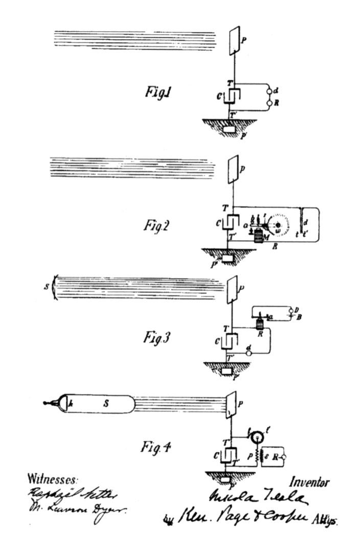
Nikola Tesla, “Method of Utilizing Radiant Energy,” U.S. Patent No. 685,958, 5 November 1901.Tesla provides more detail on this subject in another patent regarding his use of “radiant energy,” “Apparatus for the Utilization of Radiant Energy,” U.S. Patent No. 685,957, 5 November 1901. [See Fig. 5.]
Various Charge Indicators
Out of curiosity, the hookup wire and electroscope were removed from the charge deposition terminal, while the separation of the toroids was kept the same. Power was applied to the resonator for only a short period of time, in order to generate sparks. After it was turned off, when the terminal was touched, no distinct indication of discharging was sensed. This was not the case when the hookup wire and electroscope were connected. This test was repeated several times, with no change in results. It was clear that the isotropic capacity of the ten-inch charge deposition terminal was too small to support a charge that would be large enough to be detected by a simple touch of the finger.
Would applying the test lead of a sensitive electrometer to the remote conductor, after the power was quenched, show some charge deposition on the free terminal? Since the connection of the hookup wire and the electroscope add more isotropic capacity to the free terminal, what would happen if additional capacitance was added to the terminal?2
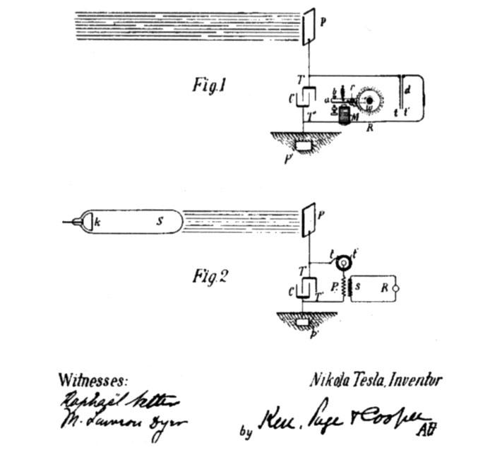
Figure 5 Elaboration on apparatus for charge buildup from U.S. Patent No. 685,957.
In further experiments, the hookup wire was connected to the electroscope, along with the string electrometer, as before. A test was run under the previous conditions to establish repeatability of the former results. Next, a 24-inch-diameter toroid was placed on an insulated support, several feet away from the charge deposition terminal, and connected via hookup wire to the free terminal. (See Fig. 6.) With this setup, when power was applied, the electroscope leaves, instead of slamming and staying together, alternately opened and closed continuously, at a slow rate of oscillation.
Meanwhile, the strands of the string indicator separated and held apart, as in previous tests, until a streamer would come close enough to discharge the free terminal, causing them to collapse. After such a discharge, the isolated, free terminal circuit quickly regained its charge, power unabated, and all indicators behaved as before.
The Pièce de Résistance
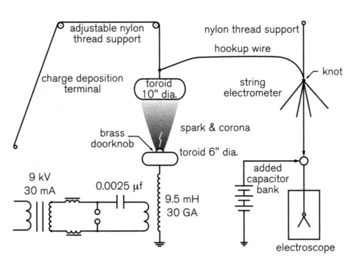
In considering the addition of even more isotropic capacity to the charge deposition terminal circuit, I realized the limitations imposed by the space available in my work area. I therefore attempted to streamline the setup. The 24-inch-diameter toroid was replaced with discrete, commercial capacitors of appropriate values. These were connected to the charge deposition terminal and ground. (See Fig. 7.)
Feeling brave, and willing to sacrifice a few of my precious commodities, I selected for the first trial run a couple of ceramic doorknob-type units. With a rating of 500 pf at 30 kV DC apiece, they were wired together in series for a combined rating of 250 pf at 60 kV DC. The charge collection terminal remained a distance of nine inches above the resonator terminal. The electroscope and string electrometer also remained as before. I was ready for the fireworks to begin.
At first, when power was supplied to the resonator, RF streamers emanated upward from the brass doorknob terminal, as before. Whatever charge was depositing on the collection terminal was being transferred to the doorknob capacitors; the electroscope leaves blew apart from one another and stood at attention, while the string indicator behaved as before but with a greater degree of separation.
When the power to the resonator was disengaged, the electroscope leaves and strands of nylon string remained in position, defying gravity. They remained this way for a lengthy period of time - a very lengthy period of time. Growing impatient, I attempted to touch the charge collection terminal, but before I could make physical contact, I received a very visible, noisy, and nasty shock to my finger. With the system thus discharged, the detectors collapsed to their neutral positions.
I then powered the system up again, charging the doorknob capacitors to see how long of a spark could be drawn between the capacitors the instant power was removed. I slowly brought a discharge wire toward the hot terminal of the doorknob assembly, and found the discharge point to be about ¾ inches away. Unquestionably this was a static discharge with some big bang behind it. I repeated the experiment several times, and always the discharge was about ¾ inches long, and no longer.
Next, I tried working with a larger capacitor bank. Having several large, doorknob-type capacitors on-hand, I employed three 2400-pf, 40 kV DC units in series, with a net result of 800 pf at 120 kV DC. The results were not quite the same. The discharge was shorter, on average about one half inch long, but brighter and accompanied by a bigger bang. This was undoubtedly due to the larger capacitive load.
Continuing to run the resonator for an extended time, using this capacitor bank and terminal spacing, resulted in multiple static discharges emanating from the charge collection terminal. At certain intervals of time, each of these discharges would merge with an RF streamer coming from the resonator discharge terminal. These sparks were characterized by a bright, white appearance, and a loud, snapping sound. This is typical of a static discharge, and certainly distinguishable from the RF discharge commonly associated with Tesla coils.
Hull's Response to Balint
Lou Balint is correct in that a sparking coil will produce charging on even relatively remote terminals. In 1993, Dave Sharpe and I published a long, definitive article fully addressing the non-sparking issue, “Tesla Coils and Electrostatics,” ESJ 9:7-13. We did not need an electrometer to prove the effect. I had charged 1.0 µf capacitors with a setup like Balint mentioned, and the details were printed in 1996, “Tesla Coils, Electric Gradients and Electrostatics,” ESJ 17:27-31. I was able to run electrostatic motors off of the accumulated charge on a remote capacity. Of course, there is little real power in this effect, for virtually no energy is transferred in this process. I am sure that a system could be devised that would boost efficiency up towards 50%, and charge to over 50 kV, but why not just use a rectifier? Neglecting to mention the non-sparking issue in the recent ESJ 35 sidebar was just an oversight - Richard Hull
Next, I wanted to employ the latest modifications in the first experiment, where the charge deposition terminal had been at its maximum displacement from the resonator terminal, and no indication of static charging was detectable on the terminal. With the terminal returned to its maximum displacement, the larger capacitor bank was used to magnify any effects, and the string electrometer was also employed. With this setup, charge was easily detected, though to a lesser extent than when the terminal was closer to the resonator. No wonder Tesla extolled the use of a capacitor connected to the terminal, saying it “magnified” the effect to a great degree, rendering it easily detectable.
Conditions for Charge Deposition
In the final series of tests, two experiments were performed to probe static charging, with and without corona. To do this, I needed a virtual on/off control for the production of corona plasma while the resonator was operating at full-tilt. Also, the charge deposition terminal needed to be in close proximity to the resonator terminal, with no major variation in spacing between the two terminals.
To accomplish this, the brass doorknob discharge terminal was removed from the top of the resonator terminal, and was not used in any of the remaining tests. An identical, six-inch-diameter toroid was then placed on top of the existing resonator terminal, and the charge deposition terminal remained at the maximum elevation above the resonator top load. Full power was applied to test the resonator, and neither sparks nor corona were observed. The tuning of the primary was not adjusted to compensate for the additional capacitive load.
The charge collection terminal, with the larger capacitor bank connected, was then lowered until the distance between the two terminals was two inches. With this spacing, when the resonator was fully powered, a beautiful, point-to-point brush discharge formed between the center of each terminal, with no distinct spark detected in the dimly-lit room. The brush discharge easily charged the collection terminal and capacitor bank to a substantial degree, easily detectable with my crude instrumentation. When power was no longer supplied to the resonator, the capacitor bank was discharged via a high-quality spark.
The other test addressed the topic and conclusion of Richard Hull’s article. The above experiment was repeated with, of course, the capacitor bank fully discharged. The only variation was that the charge collection terminal was raised one inch, for a separation of three inches, instead of two. Under these conditions, with the resonator running at full power, no spark, brush, nor corona could be seen between the two terminals in a fully darkened room. Furthermore, no charge could be detected with my crude indicators. Connecting the Keithley 150 to the capacitor bank after power to the resonator was quenched revealed no charge deposition nor charging of the capacitor bank in the mid-level, 1 mV range. It was difficult to work with more sensitive scales, and the readings obtained from them were untrustworthy.
Conclusion
As was suspected, because the operation of a non-sparking Tesla coil caused no ionization to occur, charge deposition on an isolated conductor was, for all practical purposes, nonexistent. However, when there is a spark, corona, brush, or any form of plasma emitted from the top terminal of a functioning Tesla coil, charge deposition is possible, and more pronounced the closer the isolated collection terminal is to the resonator terminal, provided it does not seriously impair the operation of the system at the critical juncture.
Notes
- About twenty years ago, the Corums provided a thorough, speculative analysis of this subject in a couple of papers they presented at early ITS Symposia: James F. Corum and Kenneth L. Corum, “Disclosures Concerning the Operation of an ELF Oscillator,” Proceedings of the Tesla Centennial Symposium, Colorado Springs: International Tesla Society, Inc., 1985; and, James F. Corum and Kenneth L. Corum, “Critical Speculations Concerning Tesla’s Invention and Applications of Single Electrode X-Ray Directed Discharges for Power Processing, Terrestrial Resonances and Particle Beam Weapons,” Proceedings of the 1986 International Tesla Symposium, Colorado Springs: International Tesla Society, Inc., 1986.
- This was subsequently tested and confirmed using a Keithley 150B microvolt ammeter. The resonator was powered for only ten seconds. After it was turned off, the meter was set up near the experiment. The negative lead was connected to the meter’s case, and a ground lead was also connected to this point. The meter was set to the volts function, on the 10 mV scale, with 100 kΩ input resistance. The positive lead was then touched to the ground point to zero the meter. Next, the lead was slowly brought toward the isolated terminal until it made contact. Instantly, the indicator needle pegged in the positive direction, then slowly returned to the zero position as the charge dissipated. This experiment was repeated several times, always with the same results.