Nikola Tesla Articles
Tesla Method of Operating Electro-Magnetic Motors
There has already been presented in the Western Electrician a description of Nikola Tesla's method of starting and operating synchronizing motors which involved the transformation of the motor from a torque to a synchronizing motor. This method consists in changing the circuit connections so that on the start the poles or resultant attraction of the field magnets of the motor were shifted or rotated by the action of the current until the motor reached synchronous speed, after which the poles were merely alternated. Mr. Tesla has recently patented another method of accomplishing this result, the main features being as follows: If an alternating current be passed through the field coils only of a motor having two energizing circuits of different self-induction and the armature coils be short circuited, the motor will have a strong torque, but little or no tendency to synchronism with the generator; but if the same current which energizes the field be passed also through the armature coils the tendency to remain in synchronism is very considerably increased. This is due to the fact that the maximum magnetic effects produced in the field at and armature more nearly coincide. In other words, a motor is constructed having independent field circuits of different self-induction. These are joined in derivation to a source of alternating currents. The armature is wound with one or more coils, which are connected with the field coils through contact rings and brushes, and around the armature coils is arranged a shunt with means for opening or closing the same. In starting this motor the shunt is closed around the armature coils. When the current is directed through the motor, it divides between the two circuits, which, by reason of their different self-induction, secure a difference of phase between the two currents in the two branches, that produces a shifting or rotation of the poles. By the alternations of current other currents are induced in the closed - or short-circuited - armature coils and the motor has a strong torque. When the desired speed is reached the shunt around the armature coils is opened and the current directed through both armature and field coils. Under these conditions the motor has a strong tendency to synchronism.
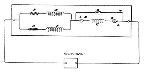
In the accompanying cuts the motor is represented diagrammaticaly. In Fig. 1 A and B designate the field coils of the motor. As the circuits including these coils are of different self-induction, they are represented by a resistance coil, R, in circuit with A, and a self-induction coil, S, in circuit with B. The same result may of course be secured by the winding of the coils. C is the armature circuit, the terminals of which are rings, M and O. Brushes, L and P bear on these rings and connect with the line and field circuits. T is the shunt or short circuit around the armature. E is the switch in this shunt. The operation of these devices is as above described.
It will be observed that in such a disposition as is illustrated in Fig. 1, the field circuits A and B being of different self-induction, there will always be a greater lag of the current in one than the other, and that, generally, the armature phases will not correspond with either, but with the resultant of both. It is therefore important to observe the proper rule in winding the armature. For instance, if the motor have eight poles - four in each circuit - there will be four resultant poles, and hence the armature winding should be such as to produce four poles, in order to constitute a true synchronizing motor.
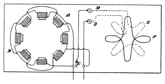
It is of advantage in the operation of motors of this kind to construct or wind the armature in such manner that when short circuited on the start it will have a tendency to reach a higher speed than that which synchronizes with the generator. For example, a given motor having say eight poles, should run, with the armature coil short-circuited, at two thousand revolutions per minute to bring it up to synchronism. It will generally happen, however, that this speed is not reached, owing to the fact that the armature and field currents do not properly correspond, so that when the current is passed through the armature (the motor not being quite up to synchronism) there is a liability that it would not "hold on," as it is termed. It is therefore prefered to so wind the motor that on the start when the armature coils are short-circuited the motor will tend to reach a speed higher than the synchronous - as, for instance, double the latter. In such case the difficulty above alluded to is not felt, for the motor will always hold up to synchronism if the synchronous speed is reached or passed. This may be accomplished in various ways, but for all practical purposes the following will suffice: The armature is wound with two sets of coils. On the start one only is short circuited, thus producing a number of poles on the armature, which will tend to run the speed up above the synchronous limit. When such limit is reached or passed, the current is directed through the other coil, which by increasing the number of armature poles, tends to maintain synchronism. In Fig. 2 such a disposition is shown. The motor having say, eight poles contains two field circuits A and B of different self-induction. The armature has two coils F and G. The coil F is closed upon itself while the coil G is connected with the field and line through contact rings M and ), and a switch E. On the start the coil F alone is active and the motor tends to run at a speed above the synchronous, but when the coil, G, is connected to the circuit the number of armature poles is increased while the motor is made a true synchronous motor.