Nikola Tesla Patents
Nikola Tesla British Patent 6527 - Improvements relating to Electro-Motors
[Third Edition.]
| No 6527 | A.D. 1889 |
Date of Application, 16th Apr., 1889 - Accepted, 18th May, 1889
COMPLETE SPECIFICATION.
[Communicated from abroad by Nikola Tesla, of the City and State of New York, United States of America, Electrician.]
Improvements Relating to Electro-Motors
I, Henry Harris Lake, of the firm of Haseltine Lake & Co., Patent Agents, 45, Southampton Buildings, in the County of Middlesex, do hereby declare the nature of this invention and in what manner the same is to be performed, to be particularly described and ascertained in and by the following statement:-
As is well known, certain forms of alternating current machines have the property, when connected in circuit with an alternating current generator, of running as a motor in synchronism therewith. But, while the alternating current will run the motor after it has attained a rate of speed synchronous with that of the generator, it will not start it, hence in all instances heretofore, where these synchronizing motors, as they are termed, have been run, some means have been adopted to bring the motors up to synchronism with the generator, or approximately so, before the alternating current of the generator is applied to drive them. In some instances mechanical appliances have been utilized for this purpose, in others, special and complicated forms of motor have been constructed.
This invention consists in a much more simple method or plan of operating synchronizing motors and one which requires practically no other apparatus than the motor itself. In other words, by a certain change in the circuit connections of the motor, it is converted at will from a double circuit motor, or such as is now known as a Tesla motor and which will start under the action of an alternating current, into a synchronizing motor, or one which will be run by the generator only when it has reached a certain speed of rotation synchronous with that of the generator.
The expression, synchronous with that of the generator, is used herein in its ordinary acceptation, that is to say, a motor is said to synchronize with the generator when it preserves a certain relative speed determined by its number of poles and the number of alternations produced per revolution of the generator. Its actual speed therefore may be faster or slower than that of the generator, but it is said to be synchronous so long as it preserves the same relative speed. In carrying out this invention a motor is constructed which has a strong tendency to synchronism with the generator. The construction preferred for this is that in which the armature is provided with polar projections. The field magnets are wound with two sets of coils, the terminals of which are connected to a switch mechanism, by means of which the line current may be carried directly through the said coils or indirectly through paths by which its phases are modified.
To start such a motor, the switch is turned on to a set of contacts which includes in one motor circuit a dead resistance, in the other an inductive resistance, and the two circuits being in derivation it is obvious that the difference in phase of the current in such circuits will set up a rotation of the motor.
When the speed of the motor has been brought to the desired rate the switch is shifted to throw the main current directly through the motor circuits and although the currents in both circuits will now be of the same phase, the motor will continue to revolve, becoming a true synchronous motor. To secure greater efficiency, the armature or its polar projections are wound with coils closed on themselves.
There are various modifications and important features of this method or plan but the main principle of the invention will be understood from the foregoing.
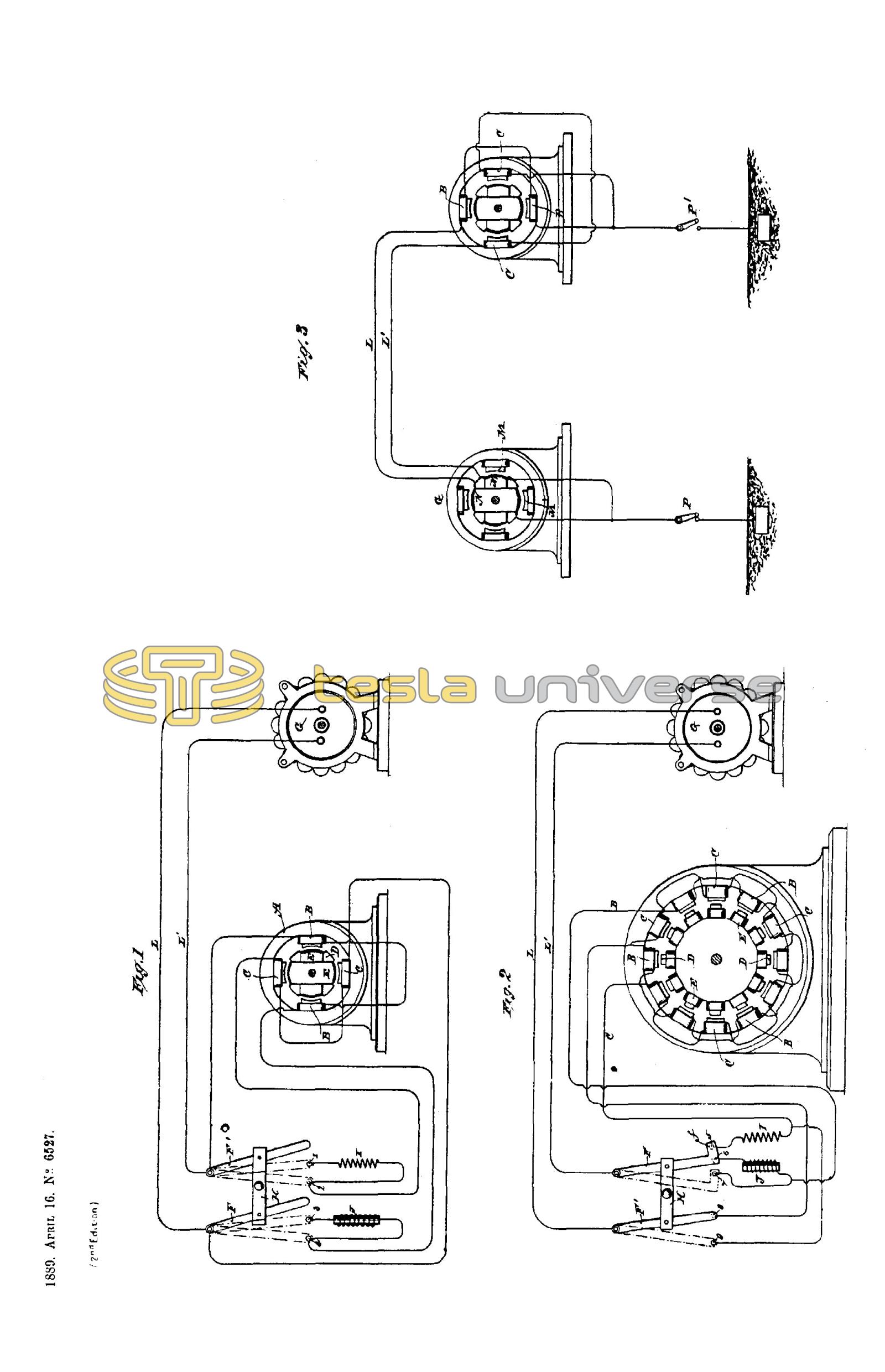
The general features of construction and operation which distinguish the present invention are illustrated in the accompanying drawing in which
Figure 1 is a view illustrating the details of the plan above set forth, and
Figures 2 and 3 are modifications of the same.
Referring to Figure 1, let A designate the field magnets of a motor, the polar projections of which are wound with coils B, C, included in independent circuits, and D the armature with polar projections wound with coils E closed upon themselves. The motor in these respects being similar in construction to that described in British Patent dated May 1st 1888, No. 6,481, but having, by reason of the polar projections on the armature core, or other similar and well known features, the properties of a synchronizing motor.
L L1, represent the conductors of a line from an alternating current generator G.
Near the motor is placed a switch the action of which is that of the one shown in the drawing, which is constructed as follows: F, F1 are two conducting plates or arms pivoted at their ends and connected by an insulting cross bar H so as to be shifted in parallelism.
In the path of the bars F, F1, is the contact 2 which forms one terminal of the circuit through coils C, and the contact 4 which is one terminal of the circuit through coils B. The opposite end of the wire of coils C is connected to the wire L or bar F1 and the corresponding end of coils B is connected to wire L1 and bar F, hence if the bars be shifted so as to bear on contacts 2 and 4, both sets of coils B, C, will be included in the circuit L, L1, in multiple arc or derivation.
In the path of the levers F, F1, are two other contact terminals 1 and 3. The contact 1 is connected to contact 2 through an artificial resistance I and contact 3 with contact 4 through a self induction coil J, so that when the switch levers are shifted on to the points 1 and 3, the circuits of coils B and C will be connected in multiple arc or derivation to the circuit L, L1, and will include the resistance and self induction coil respectively.
A third position of the switch is that in which the levers F and F1 are shifted out of contact with both sets of points. In this case the motor is entirely out of circuit.
The purpose and manner of operating the motor by these devices are as follows: The normal position of the switch, the motor being out of circuit, is off the contact points. Assuming the generator to be running and that it is desired to start the motor, the switch is shifted until its levers rest upon points 1 and 3. The two motor circuits are thus connected with the generator circuit, but by reason of the presence of the resistance I in one and the self-induction coil J in the other, the coincidence of the phases of the current is disturbed sufficiently to produce a progression of the poles which starts the motor in rotation. When the speed of the motor has run up to synchronism with the generator or approximately so the switch is shifted over onto to the points 2 and 4, thus cutting out the coils I and J so that the currents in both circuits have the same phase, but the motor now runs as a synchronous motor, which is well known to be a very desirable and efficient means for converting the transmitting power.
It will be understood that when brought up to speed the motor will run with only one of the circuits B or C connected with the main or generator circuit, or the two circuits may be connected in series. This latter plan is preferable when a current having a high number of alternations per unit of time is employed to drive the motor.
In such case the starting of the motor is more difficult and the dead and inductive resistances must take up a considerable proportion of the electro-motive force of the circuits. Generally, the conditions are so adjusted that the electro-motive force used in each of the motor circuits is that which is required to operate the motor when its circuits are in series.
The plan to be followed in this case is illustrated in Figure 2. In this diagram the motor has twelve poles and the armature has polar projections D wound with closed coils E. The switch used is of substantially the same construction as that shown in the previous Figure. There are, however, five contacts, which are designated by the figures 5, 6, 7, 8 and 9. The motor circuits B, C, which include alternate field coils are connected to the terminals in the following order: One end of circuit C is connected to contact 9, and to contact 5 through a dead resistance I. One terminal of circuit B is connected to contact 7 and to contact 6 through a self induction coil J. The opposite terminals of both circuits are connected to contact 8.
One of the levers, as F, of the switch is made with an extension f or otherwise so as to cover both contacts 5 and 6 when shifted into the position to start the motor. It will be observed that when in this position and with lever F1 on contact 8 the current divides between the two circuits B, C, which from their difference in electrical character, produce a progression of the poles that starts the motor in rotation. When the motor has attained the proper speed, the switch is shifted so that the levers cover the contacts 7 and 9, thereby connecting circuits B and C in series. It will be found that by this disposition, the motor is maintained in rotation in synchronism with the generator.
This principle of operation which consists in converting, by a change of connections, or otherwise, a double circuit motor, or one operating by a progressive shifting of the poles, into an ordinary synchronizing motor, may be carried out in many other ways for instance, instead of using the switch shown in the previous figures, a temporary ground circuit between the generator and motor may be used in order to start the motor, in substantially the manner indicated in Figure 3.
Let G in this figure represent an ordinary alternating current generator with say four poles M M1 and an armature wound with two coils N N1 at right angles and connected in series. The motor has, for example, four poles wound with coils B C which are connected in series, and an armature with polar projections D wound with closed coils E, E.
From the common joint or union between the two circuits of both the generator and the motor and earth connection is established while the terminals or ends of the said circuits are connected to the line.
Assuming that the motor is a synchronizing motor or one that has the capability of running in synchronism with the generator but not of starting, it may be started by the above described apparatus by closing the ground connection from both generator and motor.
The system thus becomes one with a two circuit generator and motor, the ground forming a common return for the currents in the two circuits L and L1. When by this arrangement of circuits the motor is brought to speed the ground connection is broken between the motor or generator or both and ground, switches P P1 being employed for this purpose. The motor then runs as a synchronizing motor.
In the description of those features which constitute the invention, illustrations are omitted of the appliances used in conjunction with the electrical devices of similar systems, such for instance, as driving belts, fixed and loose pulleys for the motor, and the like. But these matters well understood.
This invention though described by reference to specific apparatus is not confined to the use of that shown, but includes generally the method or plan of operating motors by first producing a progressive movement or rotation of their poles or points of maximum effect and then, after the motor has reached a certain speed, alternating its poles, or in other words, by a change in the order or character of the circuit connections, to convert a motor operating on one principle to one operating on another, for the purpose described.
Having now particularly described and ascertained the nature of the said invention and in what manner the same is to be performed as communicated to me by my foreign correspondent I declare that what I claim is:-
First. The method of operating an alternating current motor herein described by first progressively shifting or rotating its poles or points of greatest attraction and then, when the motor has attained a given speed, alternating the said poles, as described.
Second. The method of operating an electro-magnetic motor herein described which consists in passing through independent energizing circuits of the motor alternating currents differing in phase and then, when the motor has attained a given speed, alternating currents coinciding in phase, as described.
Third. The method of operating an electro-magnetic motor herein described which consists in starting the motor by passing alternating currents differing in phase through independent energizing circuits, and then, when the motor has attained a given speed, joining the energizing circuits in series and passing an alternating current through the same.
Fourth. The method of operating a synchronizing motor which consists in passing an alternating current through independent energizing circuits of the motor and introducing into such circuits a resistance and self-induction coil whereby a difference of phase between the currents in the circuits will be obtained and then, when the speed of the motor synchronizes with that of the generator, withdrawing the resistance and self-induction coil, as set forth.
Dated this 16th day of April 1889.
Haseltine, Lake & Co.,
45, Southampton Buildings, London, Agents for the Applicant.