Nikola Tesla Patents
Nikola Tesla U.S. Patent 335,786 - Electric-Arc Lamp
NIKOLA TESLA, OF SMILJAN LIKA, AUSTRIA-HUNGARY, ASSIGNOR TO THE TESLA ELECTRIC LIGHT AND MANUFACTURING COMPANY, OF RAHWAY, NEW JERSEY.
ELECTRIC-ARC LAMP.
SPECIFICATION forming part of Letters Patent No. 335,786, dated February 9, 1886.
Application filed March 30, 1885. Serial No. 160,574. (No model.)
To all whom it may concern:
Be it know that I, NIKOLA TESLA, of Smiljan Lika, border country of Austria-Hungary, have invented certain new and useful Improvements in Electric-Arc Lamps, of which the following is a specification.
My invention relates more particularly to those arc-lamps in which the separation and feed of the carbon electrodes or their equivalents is accomplished by means of electromagnets or solenoids in connection with suitable clutch-mechanism; and it is designed to remedy certain faults common to the greater part of the lamps heretofore made.
The objects of my invention are to prevent the frequent vibrations of the movable electrode and flickering of the light arising therefrom, to prevent the falling into contact of the electrodes, to dispense with the dash-pot, clockwork, or gearing and similar devices heretofore used, and to render the lamp extremely sensitive, and to feed the carbon almost imperceptibly, and thereby obtain a very steady and uniform light.
In that class of lamps where the regulation of the arc is effected by forces acting in opposition on a free movable rod or lever directly connected with the electrode, all or some of the forces being dependent on the strength of the current, any change in the electrical condition of the circuit causes a vibration and a corresponding flicker in the light. This difficulty is most apparent when there are only a few lamps in circuit. To lessen this difficulty; lamps have been constructed in which the lever or armature, after the establishing of the arc, is kept in a fixed position and cannot vibrate during the feed operation, the feed-mechanism acting independently; but in these lamps, when a clamp is employed, it frequently occurs that the carbons come into contact and the light is momentarily extinguished, and, frequently, parts of the circuit are injured. In both these classes of lamps it has been customary to use dash-pot, clockwork, or equivalent retarding devices; but these are generally unreliable and objectionable, and increase the cost of construction.
My invention is intended to effect the desired objects and to remedy the before-mentioned defects. I combine two electro-magnets—one of low resistance in the main or lamp-circuit, and the other of a comparatively high resistance in a shunt around the arc—a movable armature-lever, and a novel feed-mechanism, the parts being arranged so that in the normal working position of the armature-lever the same is kept almost rigidly in one position, and is not effected even by considerable changes in the electric circuit; but if the carbons fall into contact the armature will be actuated by the magnets so as to move the lever and start the arc, and hold the carbons until the arc lengthens and the armature-lever returns to the normal position. After this the carbon rod holder is released by the action of the feed-mechanism, so as to feed the carbon and restore the arc to its normal length.
My invention consists, mainly, in the particular manner in which the armature is combined with the magnets and acted upon by them and in the feed-controlling mechanism.
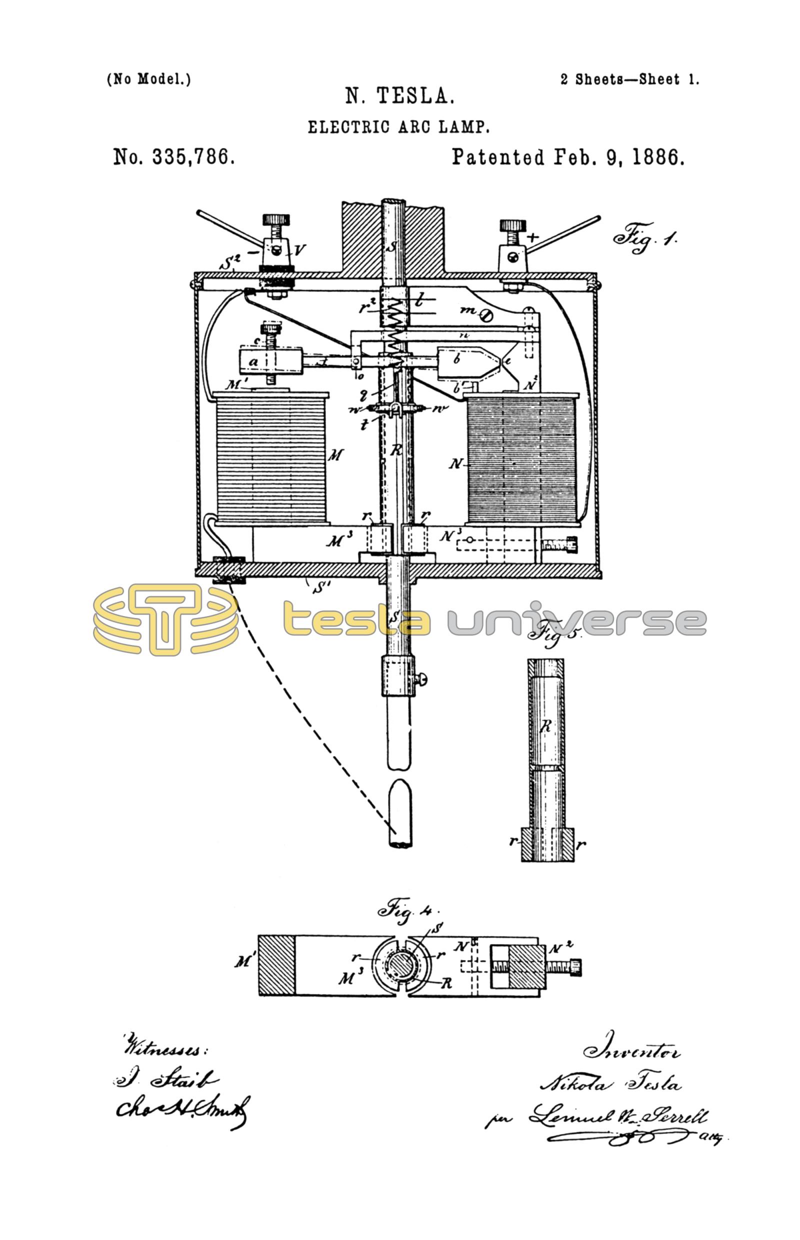
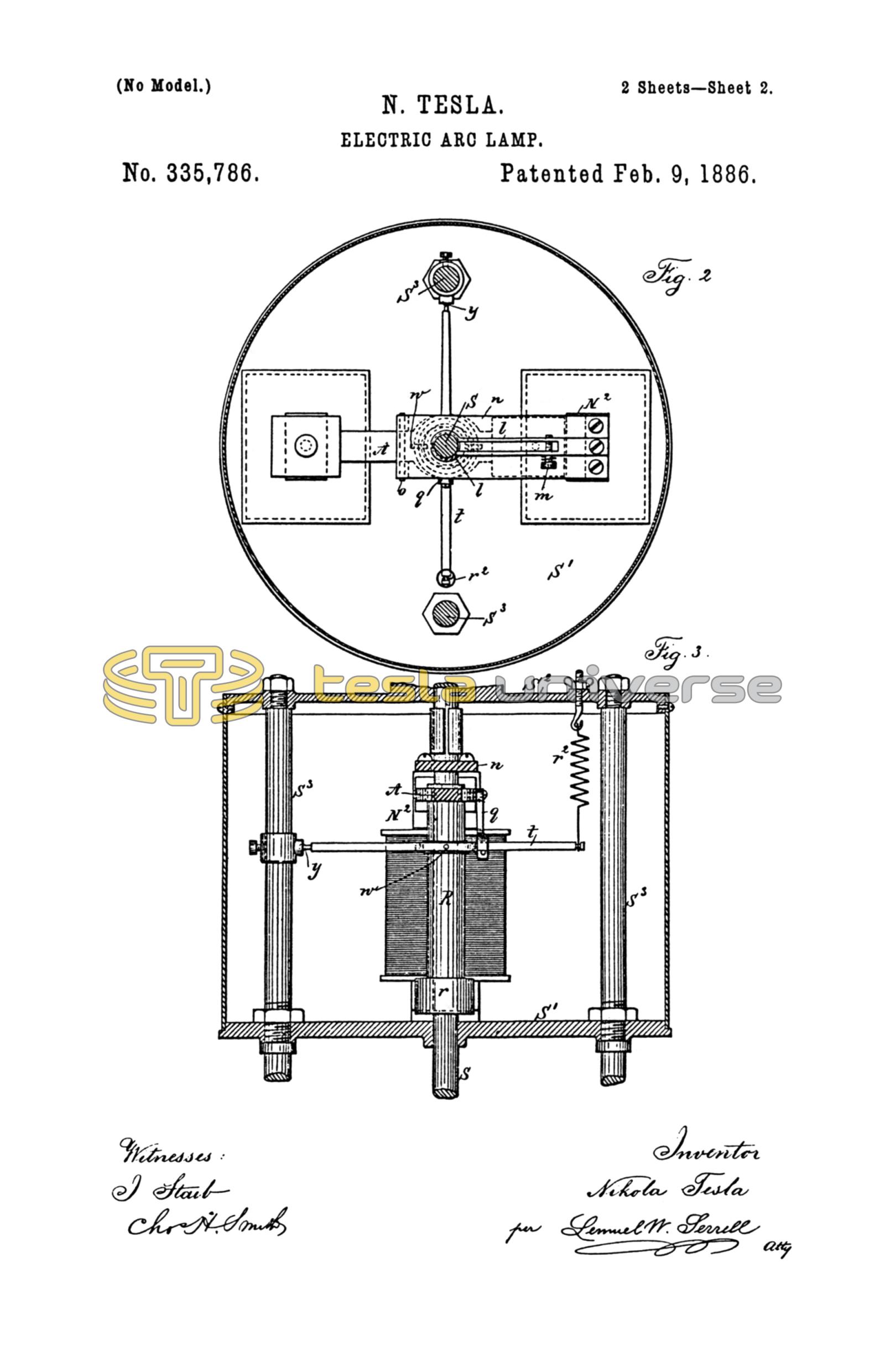
In the drawings, Figure 1 is an elevation of the mechanism made use of in the electric lamp. Fig. 2 is a plan view of the same below the line x x , Fig. 3 is an elevation of the balancing lever and spring, and Fig. 4 is a detached plan view of the pole-pieces and armatures upon the friction-clamp, and Fig. 5 is a section of the clamping-tube.
M is a helix of coarse wire in a circuit from the lower carbon holder to the negative binding-screw -.
N is a helix of the fine wire in a shunt between the positive binding-screw + and the negative binding-screw -. The upper carbon holder S is a parallel rod sliding through the plates S' S2 of the frame of the lamp, and hence the electric current passes from the positive binding-post + through the plate S2, carbon-holder S, and upper carbon to the lower carbon, and thence by the holder and a metallic connection to the helix M.
The carbon-holders are of any desired character, and to insure electric connections the springs l are made use of to grasp the upper carbon holding rod S, but to allow the rod to slide freely through the same. These springs l may be adjusted in their pressure by the screw m, and the spring l may be sustained upon any suitable support. I have shown them as connected with the upper end of the core of the magnet N.
Around the carbon-holding rod S, between the plates S' S2, there is a tube, R, which forms a clamp. This tube is counterbored, as seen in the section Fig. 5, so that it bears upon the rod S at its upper end and near the middle, and at the lower end of this tubular clamp R there are armature-segments r of soft iron. A frame or arm, n, extending, preferably, from the core N2, supports the lever A by a fulcrum-pin, o, This lever A has a hole, through which the upper end of the tubular clamp R passes freely, and from the lever A is a link, q, to the lever t, which lever is pivoted at y to a ring upon one of the columns S3. This lever t has an opening or bow surrounding the tubular clamp R, and there are pins or pivotal connections w between the lever t and this clamp R, and a spring, r2, serves to support or suspend the weight of the parts and balance the same, or nearly so. This spring is preferably adjustable.
At one end of the lever A is a soft iron armature block, a, over the core M' of the helix M, and there is preferably a limiting-screw, c, passing through this armature-block a, and at the other end of the lever A is a soft iron armature-block, b, with the end tapering or wedge-shaped, and the same comes close to and in line with the lateral projection e on the core N2. The lower ends of the cores M' N2 are made with lateral projecting pole-pieces M3 N3, respectively, and these pole-pieces are concave at their outer ends, and are at opposite sides of the armature-segments r at the lower end of the tubular clamp R.
The operation of these devices is as follows: In the condition of inaction the upper carbon rests upon the lower one, and when the current is turned on the electricity passes freely, by the frame and spring l, through the rod S and carbons to the coarse wire and helix M and to the negative binding-post V, and the core M' thereby is energized. The pole-piece M3 attracts the armature r, and by the lateral pressure causes the clamp R to grasp the rod S', and the lever A is simultaneously moved from the position shown by dotted lines, Fig, 1, to the normal position shown in full lines, and in so doing the link q and lever t are raised, lifting the clamp R and the rod S, separating the carbons and forming the arc. The magnetism of the pole-piece e tends to hold the lever A level, or nearly so, the core N2 being energized by the current in the shunt which contains the helix N. In this position the lever A is not moved by ordinary variation in the electric current because the armature b is strongly attracted by the magnetism of e, and these parts are close to each other, and the magnetism of e acts at right angles to the magnetism of the core M'. If, now, the arc becomes too long, the current through the helix M is lessened, and the magnetism of the core N3 is increased by the greater current passing through the shunt, and this core N3 attracting the segmental armature r lessens the hold of the clamp R upon the rod S, allowing the latter to slide and lessen the length of the arc, which instantly restores the magnetic equilibrium and causes the clamp R to hold the rod S. If it happens that the carbons fall into contact, then the magnetism of N2 is lessened so much that the attraction of the magnet M will be sufficient to move the armature a and lever A so that the armature b passes above the normal position, so as to separate the carbons instantly; but when the carbons burn away a greater amount of current will pass through the shunt until the attraction of the core N2 will overcome the attraction of the core M' and bring the armature-lever A again into the normal horizontal position, and this occurs before the feed can take place. The segmental armature pieces r are shown as nearly semi-circular. They may be square or of any other desired shape, the ends of the pole-pieces M3 N3 being made to correspond in shape.
I claim as my invention—
1. The combination, in an electric-arc lamp, of the electro-magnets in the main and shunt circuits, respectively, an armature-lever and connection to the movable carbon-holder, the core of the shunt-magnet passing across the end of the armature-lever, substantially as set forth, so that the two magnets act in conjunction on the armature-lever in moving the carbon to form the arc and in opposition to each other beyond the normal position of the armature-lever, substantially as specified.
2. The combination, with the carbon-holders, of two magnets, one in the main-circuit and an armature-lever to draw the arc, and a feeding-mechanism and pole-pieces upon the electro-magnets to act upon the feeding mechanism, substantially as specified.
3. The combination, with the carbon-holders, of two magnets, one in the main-circuit and the other in a shunt-circuit, and an armature-lever between two poles of such electro-magnets to draw the arc, and a feeding-mechanism and pole-pieces upon the other two poles of the electro-magnets to act upon the feeding mechanism, substantially as specified.
4. The combination, with the carbon-holding rod in an electric-arc lamp, of the clamp R, lever t, spring r2, armature-lever A, and electro-magnets M N in the main and shunt-circuits, respectively, the pole-pieces M3 N3, and armature-segments r, substantially as set forth.
5. The combination, with the carbon-holder, of a tubular clamp surrounding the same, an armature-lever connected to said tubular clamp, and electro-magnets in the main and shunt-circuits, respectively, and armature-segments upon the tubular clamp adjacent to the lateral poles of the electro-magnets, substantially as set forth.
6. In an electric-arc lamp, the combination, with the carbon-holding rod, of a clamp, two armatures upon the clamp, and electromagnets in the main and shunt-circuits, respectively, the poles of which act upon the armatures of the clamp for bringing the same into action or releasing it, substantially as set forth.
Signed by me this 25th day of March, A.D. 1885.
NIKOLA TESLA.
GEO. T. PINCKNEY,
CHAS. H. SMITH.