Nikola Tesla Patents
Nikola Tesla U.S. Patent 609,246 - Electric Circuit Controller
NIKOLA TESLA, OF NEW YORK, N. Y.
ELECTRIC-CIRCUIT CONTROLLER.
SPECIFICATION forming part of Letters Patent No. 609,246, dated August 16, 1898.
Application filed February 28, 1898. Serial No. 671,897. (No model.)
To all whom it may concern:
Be it known that I, NIKOLA TESLA, a citizen of the United States, residing in the borough of Manhattan, in the city, county, and State of New York, have invented certain new and useful Improvements in Electric-Circuit Controllers, of which the following is a specification, reference being had to the drawing accompanying and forming a part of the same.
The invention which forms the subject of my present application is an improvement in a novel class of circuit-controlling appliances heretofore invented by me and more especially designed to be used with my now well-known apparatus for the production of electric currents of high frequency by means of condenser-discharges, but applicable generally as a means for making and breaking an electric circuit.
In the circuit-controllers of the particular class or type to which my present improvement pertains I have utilized a conducting liquid as one of the terminals and have employed as the other terminal a solid conductor and provided various means for bringing the two into rapidly-intermittent contact.
The distinguishing feature of my present improvement lies chiefly in the use of a conducting liquid for both the terminals under conditions which permit of a rapidly-intermittent contact between them, as will be herein set forth.
The accompanying drawing illustrates an apparatus embodying the principle of my said improvement.
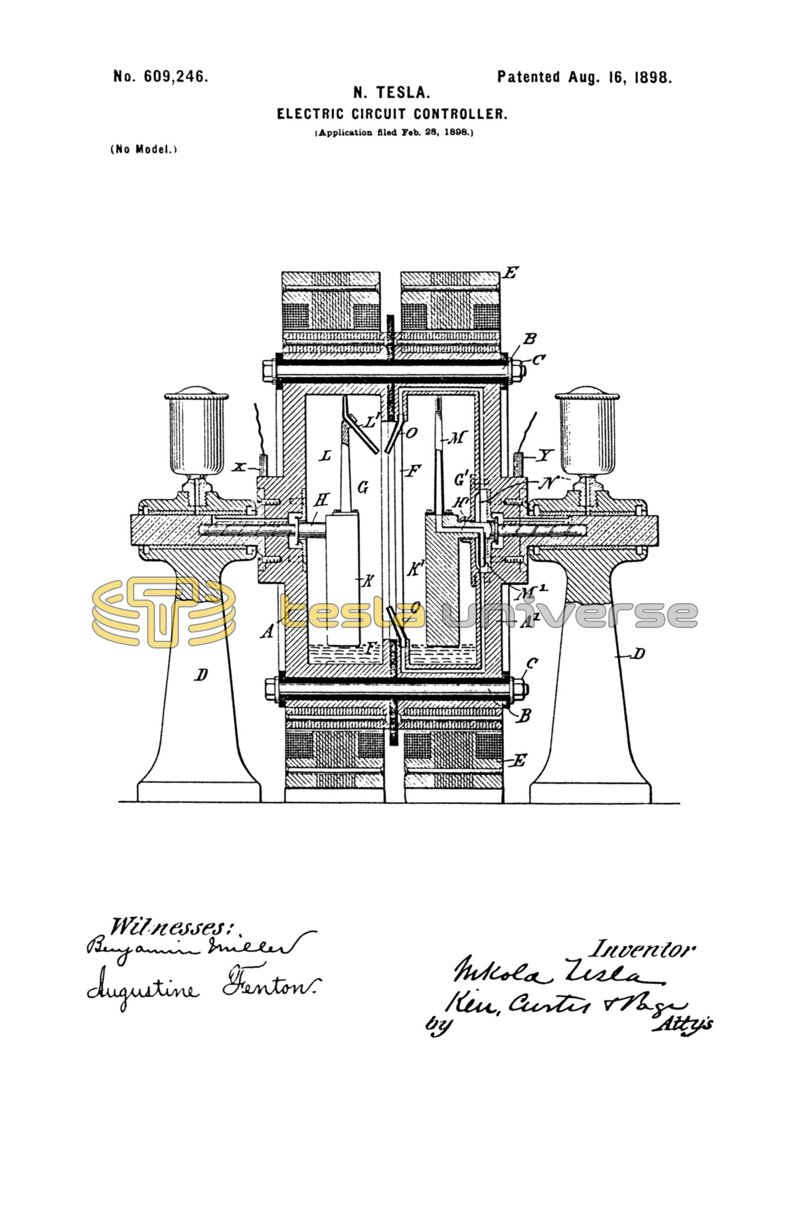
The figure is a central vertical section of the circuit-controller.
In the drawing is shown a receptacle composed of two cylindrical metallic portions A A', secured together by bolts B and nuts C, but insulated from each other. The receptacle is journaled, by means of trunnions formed on or secured to its ends, in standards D D, and any suitable means is employed to impart rotation to it. This is conveniently effected by constructing or organizing the receptacle in such manner that it may serve as the rotating element of an electromagnetic motor in conjunction with a surrounding stationary element E E. The abutting ends of the two parts of the receptacle are formed with inwardly-extending flanges F, which divide the peripheral portions of the receptacle into two compartments G G'. Into one of these compartments, as G, extends a spindle H, having its bearing in the end of the part A and the trunnion secured to or extending therefrom. Into the other compartment G' extends a spindle H', similarly journaled in the end of part A' and its trunnion. Each spindle carries or is formed with a weighted arm K, which, remaining in a vertical position, holds its spindle stationary when the receptacle is revolved.
To the weighted arm of spindle H is secured a standard L, carrying a tube L', with one open end in close proximity to the inner peripheral wall of the compartment G and the other directed toward the axis, but inclined toward the opposite compartment. To the weighted arm of spindle H' is similarly secured a standard M, which is hollow and constitutes a portion of a duct or passage which extends through a part of the spindle and opens through a nozzle M' into a circular chamber N in the wall of the part A'. From this chamber run passages N' to nozzles O, in position to discharge jets or streams of liquid in such directions as to intersect, when the nozzles are rotated, a stream issuing from the end of tube L'.
In each portion or compartment of the receptacle is placed a quantity of a conducting liquid, such as mercury, and the ends of the tubes L' and M are provided with openings which take up the mercury when on the rotation of the receptacle it is carried by centrifugal force against the peripheral wall. The mercury when taken up by the tube L' issues in a stream or jet from the inner end of said tube and is projected into the compartment G'. The mercury taken up by the tube M runs into the circular chamber N, from which it is forced through the passages N' to the nozzles O, from which it issues in jets or streams directed into the compartment G. As the nozzles O revolve with the receptacle the streams which issue from them will therefore be carried across the path of the stream which issues from the tube L' and which is stationary, and the circuit between the two compartments will be completed by the streams whenever they intersect and interrupted at all other times.
The continuity of the jets or streams is not preserved ordinarily to any great distance beyond the orifices from which they issue, and hence they do not serve as conductors to electrically connect the two sides of the receptacle beyond their point of intersection with each other.
It will be understood that so far as the broad feature of maintaining the terminal jets is concerned widely-different means may be employed for the purpose and that the spindles mounted in free bearings concentrically with the axis of rotation of the receptacle and held against rotation by the weighted arms constitute but one specific way of accomplishing this result. This particular plan, however, has certain advantages and may be applied to circuit-controllers of this class generally whenever it is necessary to maintain a stationary or nearly stationary body within a rotating receptacle. It is further evident from the nature of the case that it is not essential that the jet or jets in one compartment or portion of the instrument should be stationary and the others rotating, but only that there should be such relative movement between them as to cause the two sets to come into rapidly-intermittent contact in the operation of the device.
The number of jets, whether stationary or rotating, is purely arbitrary; but since the conducting fluid is directed from one compartment into the other the aggregate amount normally discharged from the compartments should be approximately equal. However, since there always exists a tendency to project a greater quantity of the fluid from that compartment which contains the greater into that which contains the lesser amount no difficulty will be found in this respect in maintaining the proper conditions for the satisfactory operation of the instrument.
A practical advantage, especially important when a great number of breaks per unit of time is desired, is secured by making the number of jets in one compartment even and in the other odd and placing each jet symmetrically with respect to the center of rotation. Preferably the difference between the number of jets should be one. By such means the distances between the jets of each set are made the greatest possible and hurtful short-circuits are avoided.
For the sake of illustration let the number of jets or nozzles L' in one compartment be nine and the number of those marked O in the other compartment ten. Then by one revolution of the receptacle there will be ninety makes and breaks. To attain the same result with only one jet, as L', it would be necessary to employ ninety jets O in the other compartment, and this would be objectionable, not only because of the close proximity of the jets, but also of the great quantity of fluid required to maintain them.
In the use of the instrument as a circuit-controller it is merely necessary to connect the two insulated parts of the receptacle to the two parts of the circuit, respectively, as by causing brushes X Y, connected with circuit-wires, to bear at any suitable points on the said two parts A A'.
In instruments of this character in which both terminals are formed by a liquid element there is no wear or deterioration of the terminals and the contact between them is more perfect. The durability and efficiency of the devices are thus very greatly increased.
Having now described my invention, what I claim is—
1. A circuit-controller comprising in combination means for producing streams or jets of conducting liquid forming the terminals, and means for bringing the jets or streams of the respective terminals into intermittent contact with each other, as set forth.
2. In a circuit-controller, the combination with two sets of orifices adapted to discharge jets in different directions, means for maintaining jets of conducting liquid through said orifices, and means for moving said orifices relatively to each other so that the jets from those of one set will intermittently intersect those from the other, as set forth.
3. The combination in a circuit-controller of ducts and means for discharging therefrom streams or jets of conducting fluid in electrical contact with the two parts of the circuit respectively, the orifices of said ducts being capable of movement relatively to each other, whereby the streams discharged therefrom will intersect at intervals during their relative movement, and make and break the electric circuit, as set forth.
4. In a circuit-controller the combination with one or more stationary nozzles and means for causing a conducting fluid forming one terminal to issue therefrom, of one or more rotating tubes or nozzles, means for causing a conducting liquid forming the other terminal to issue therefrom, the said rotating nozzles being movable through such a path as to cause the liquid issuing therefrom to intersect that from the stationary nozzles as set forth.
5. The combination with a rotating receptacle divided into two insulated compartments, a spindle in one compartment with its axis concentric with that of the receptacle, means for opposing the rotation of said spindle, and a tube or duct carried by the spindle and adapted to take up a conducting fluid at one end from the inner periphery of the compartment when the receptacle is rotated and direct it from the other end into the other compartment, of a similar spindle in the other compartment and means for opposing its rotation, a tube carried by the spindle and having an opening at one end near the inner periphery of the compartment and discharging into a chamber from which lead one or more passages to nozzles fixed to the rotating receptacle and adapted to discharge across the path of the jet from the stationary nozzle, as set forth.
6. In a circuit-controller the combination with a rotating receptacle of a body mounted therein and formed or provided with a weighted portion eccentric to this axis which opposes its rotation and a tube or duct carried by said body and adapted to take up a conducting fluid from the rotating receptacle, as set forth.
7. In a circuit-controller the combination of two sets of nozzles and means for projecting from the same, jets of conducting fluid which constitute respectively the terminals of the controller, means for moving the nozzles relatively to each other so that the jets of the two sets are brought successively into contact, the nozzles of each set being arranged symmetrically about an axis of rotation, there being one more nozzle in one set than in the other.
NIKOLA TESLA.
M. LAWSON DYER,
G. W. MARTLING.