Plans
Make Your Own Fantastic Tesla Coil
In the mind of the electrical genuis it's named for, it was a practical transmitter - but our version is strictly for thrills.
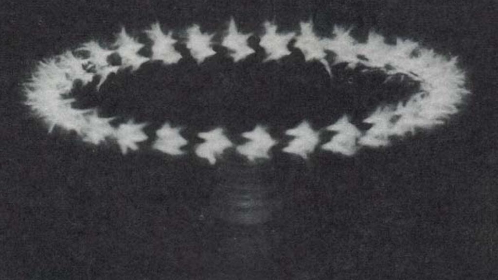

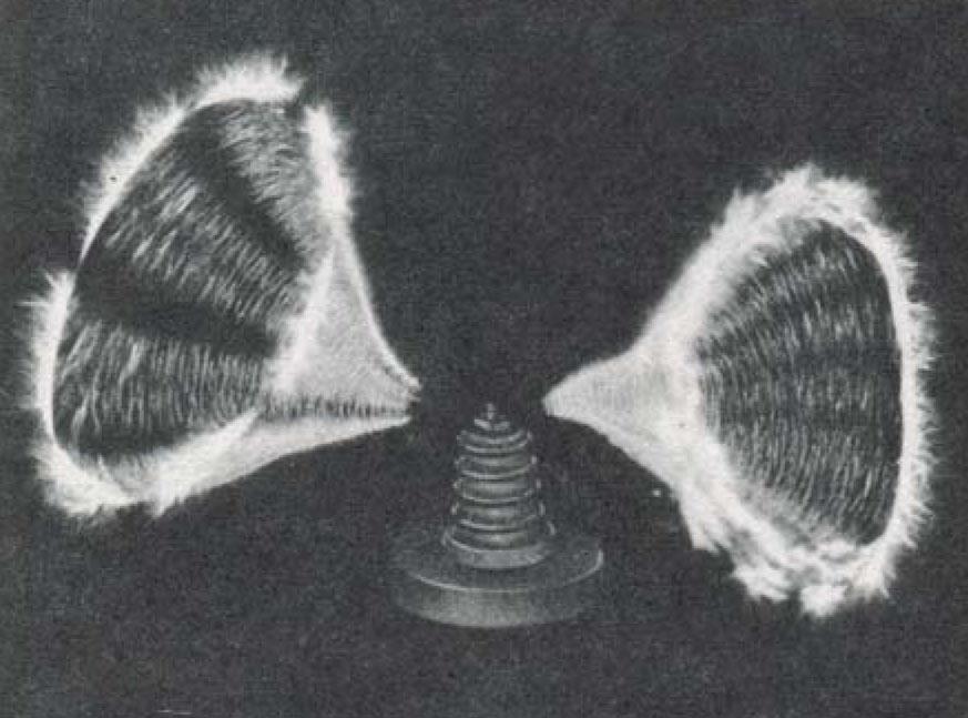
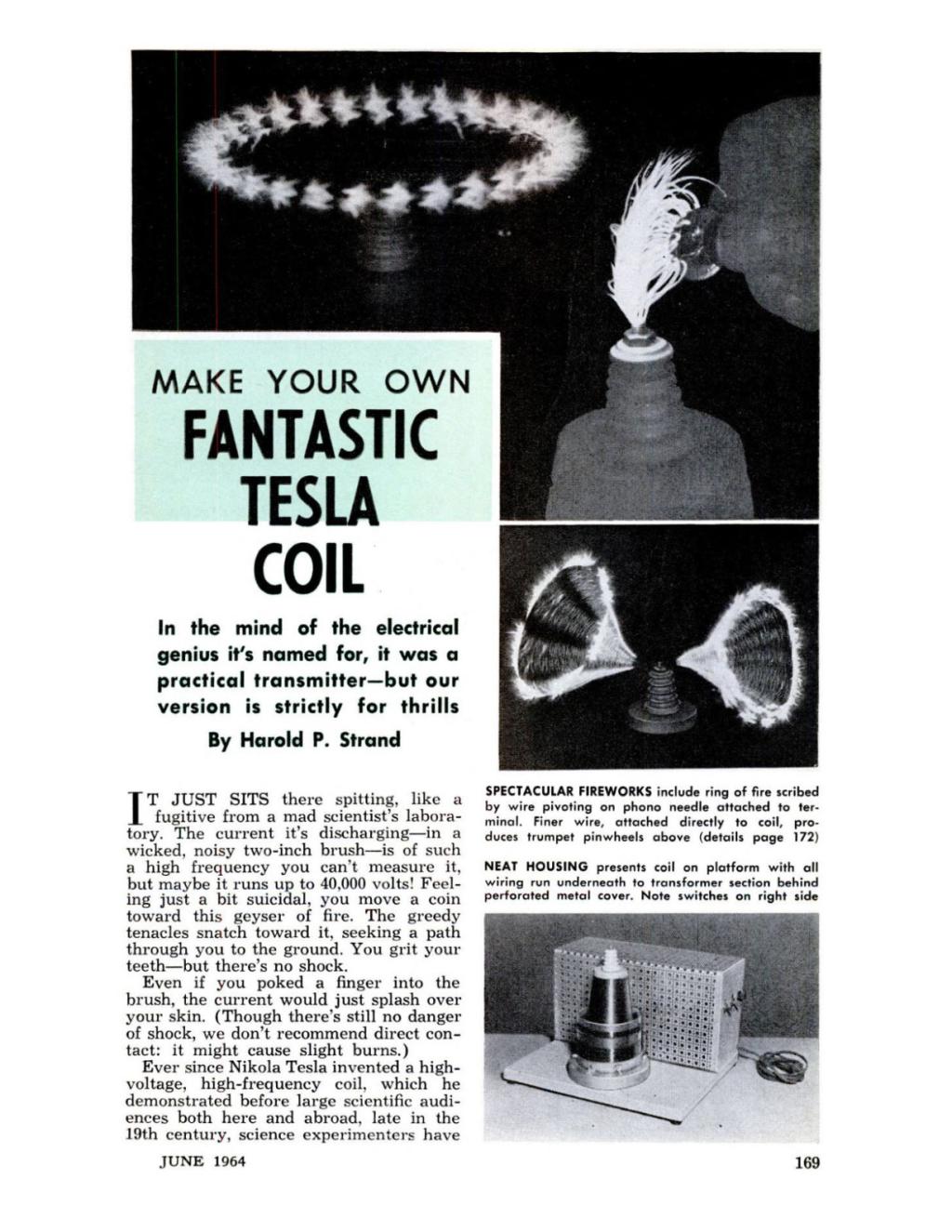
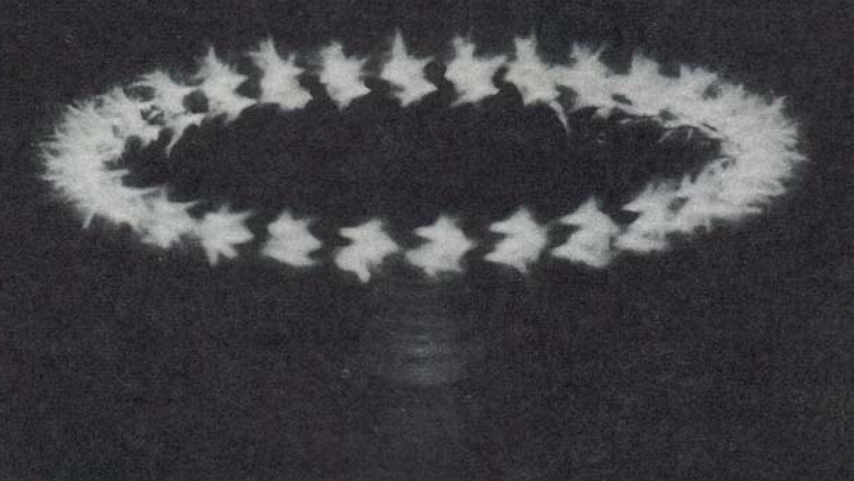
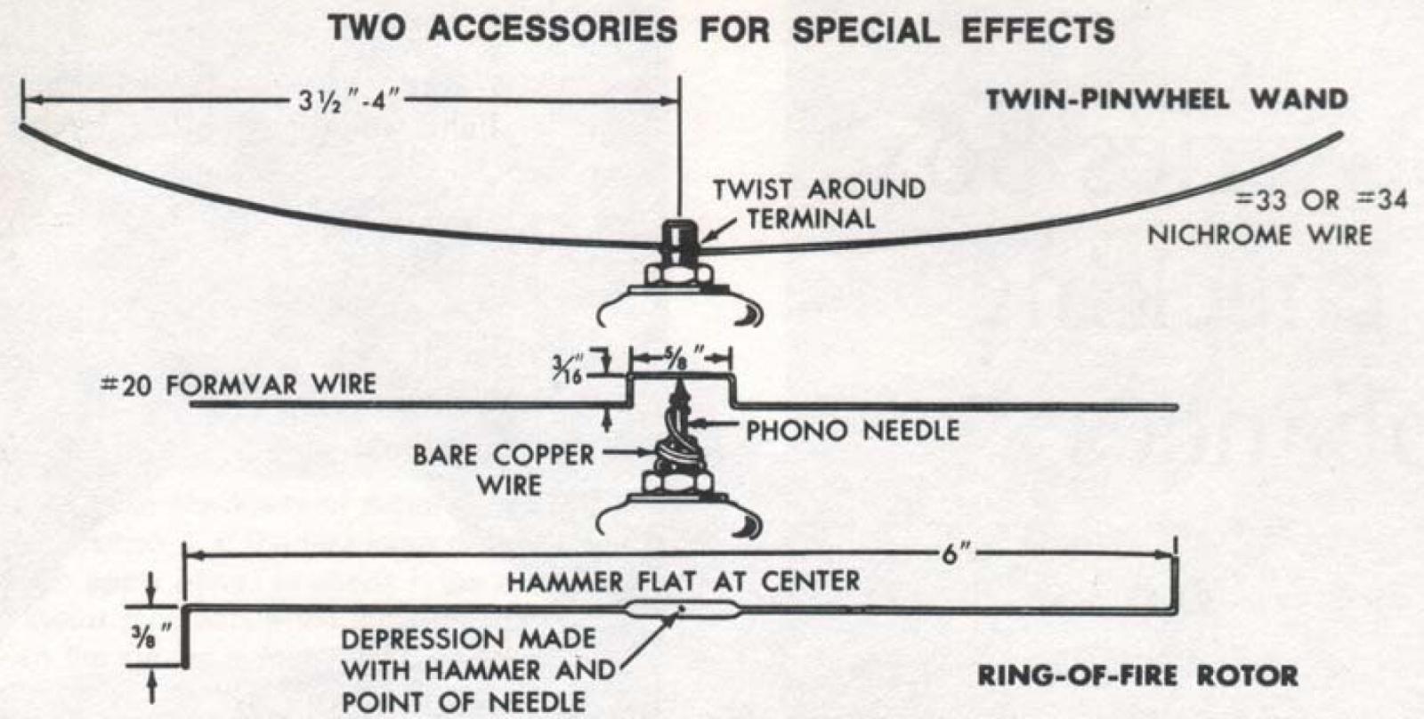
Spectacular fireworks include a ring of fire scribed by wire pivoting on a phonograph needle attached to a terminal. Finer wire, attached directly to coil, produces trumpet pinwheels above (details page 172).

It just sits there spitting, like a fugitive from a mad scientist’s laboratory. The current it’s discharging - in a wicked, noisy two-inch brush - is of such a high frequency you can’t measure it, but maybe it runs up to 40,000 volts! Feeling just a bit suicidal, you move a coin toward this geyser of fire. The greedy tentacles snatch toward it, seeking a path through you to the ground. You grit your teeth - but there’s no shock.
Even if you poked a finger into the brush, the current would just splash over your skin. (Though there's still no danger of shock, we don't recommend direct contact: it might cause slight burns.)
Ever since Nikola Tesla invented a high-voltage, high-frequency coil, which he demonstrated before large scientific audiences both here and abroad, late in the 19th century, science experimenters have been intrigued with their own variations on his coil. In Tesla’s time, high-frequency current was obtained with an induction coil as a primary source of power and Leyden jars serving as capacitors, with a spark gap and the inductance of a second coil combining to form an oscillatory discharge of high frequency. With today’s vacuum tubes and mica capacitors, we can make a much more efficient coil - and one that's safer to use.
Our small model operates at a resonant frequency of about 850 kilocycles, but this will depend somewhat on the tap selected on the lower outer coil, and the value of the capacitance used across it.
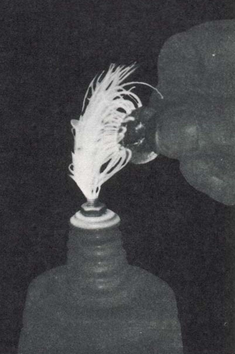
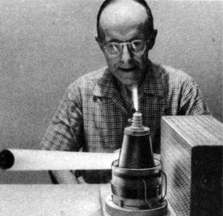
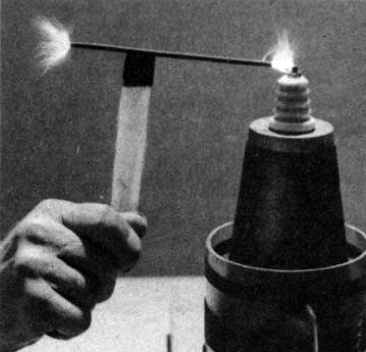
The coil stunt isn't even the best fun you can have with a Tesla coil. With the center of a length of Nichrome wire around the terminal with the ends formed out straight, like feelers. The ends become red hot and bright lavender sparks quiver along the wire as each half begins to rotate. Two fiery trumpets blaze forth in the darkened room. Just why the wire ends rotate is not known - maybe you can figure it out.
Another bit of fireworks results when you balance a wire rotor (detailed in the panel below) on the point of a phonograph needle erected on the terminal. Jet propulsion from the corona discharges at each end sets the rotor spinning. The result is a startling ring of fire.
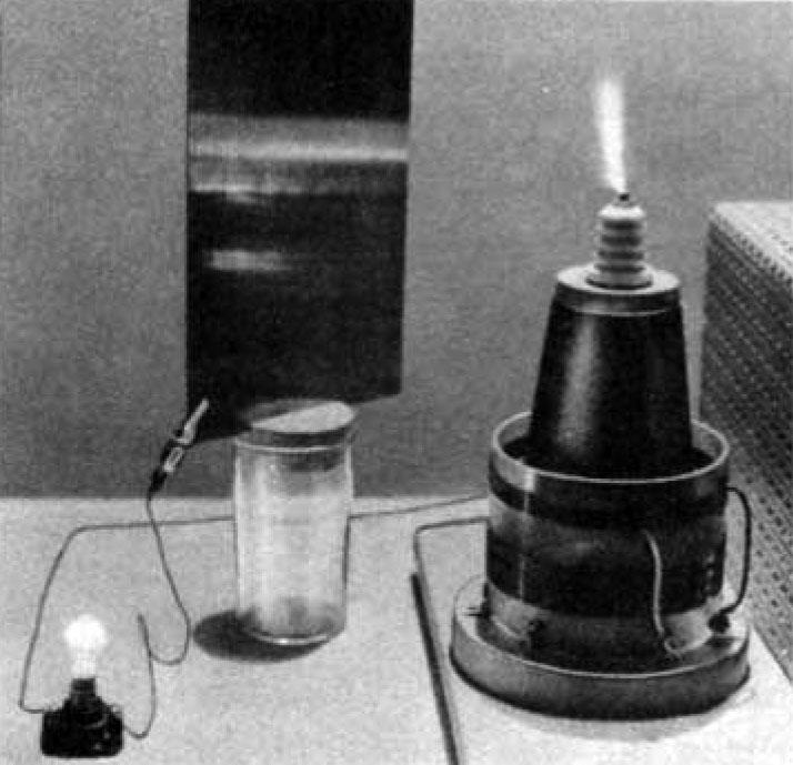
Less spectacular, but no less intriguing, are the three demonstrations above. Holding a fluorescent tube near the coil activates the phosphors on the inside, causing a mysterious glow. Various types of neon lamps will also light when introduced into the coil’s field. Since this field is strongest near the coil as you draw the lamp away it dims, then goes out.
The center experiment, above, illustrates Tesla's dream of lighting entire buildings from a distance without wires. As shown, you erect a sheet of aluminum on an insulating stand, to serve as a collector for currents radiating from the coil. Attach one clip lead to the plate and to one side of a small 115-volt lamp; another clip lead connects the other side of the lamp to ground. When the coil is switched on, the plate picks up energy and lights the lamp. The closer the plate is moved to the coil, the brighter the lamp glows. If you disconnect the lamp, you can draw sparks from the plate to your fingers, indicating that the plate is charged by radiation from the coil. Tesla did actually build a large coil apparatus in Colorado to test this idea, but it proved too inefficient for practical use.
Another experiment (not shown) demonstrates that this peculiar form of current seems to pass through material that’s considered a good insulator. A piece of 1/4-in. plastic, held in a spark gap connected from the top terminal and the ground post, seems to offer no resistance - you can watch the discharge continue to jump the gap. You can also conduct this experiment with other insulation materials of various thicknesses.
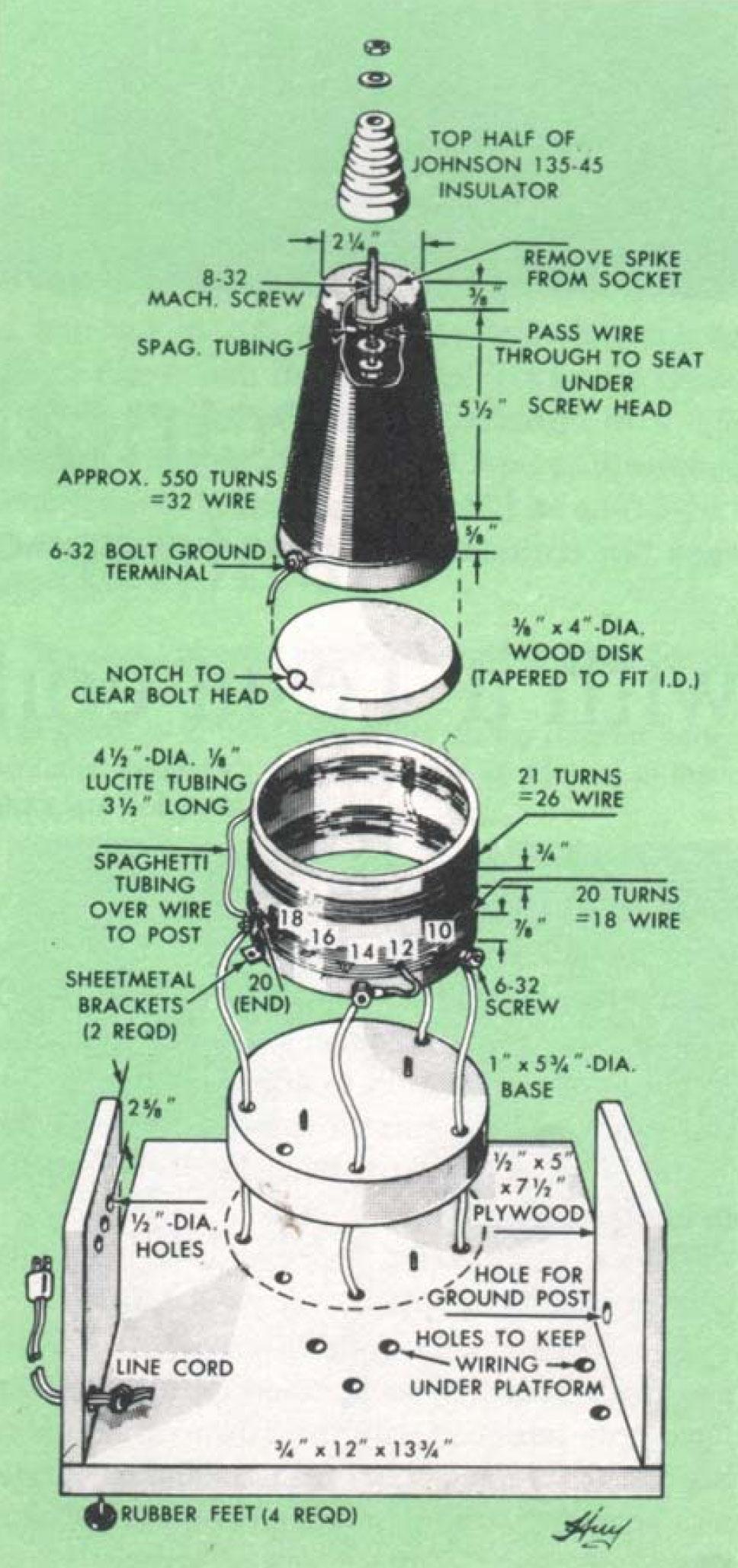
Start construction with the tall, tapered core coil. The winding form is a plastic flower vase with a stake base, sold in variety and garden stores. Be sure it’s plastic - metal won't, of course, do. Remove the spike by pulling it out of its socket and drill a center hole through the socket bottom for a machine screw long enough to pass through the top insulator. At the large end make up a plywood disk with tapering edges, to exactly fit the opening. Drill three equally spaced holes through the edge of the vase for small escutcheon pins, driven into the plywood edge. Fastening is temporary, as the disk must be removed to make interior connections.
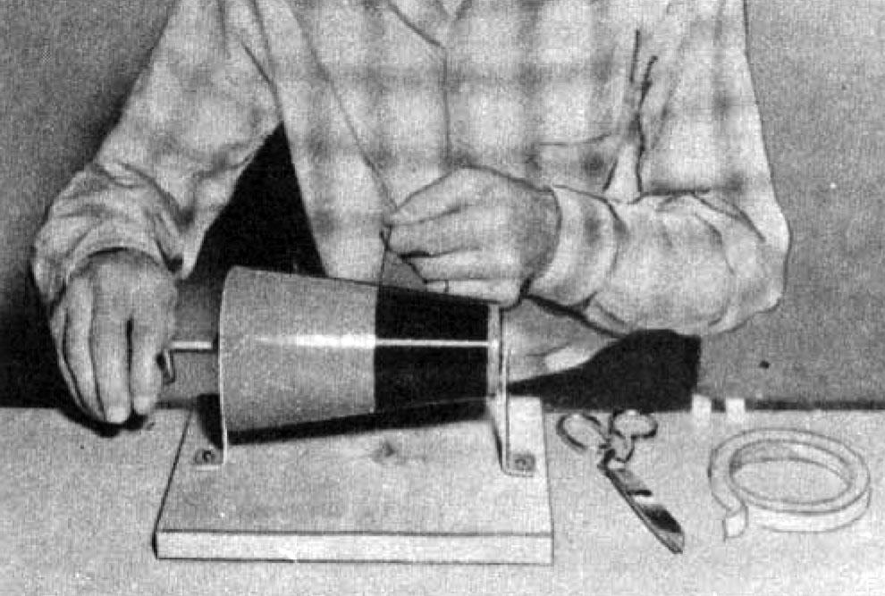
Bore a center hole in the disk to pass whatever axel you’ve devised for the winding process. One type of jig is shown in the top-left photo, page 171. An even simpler setup would be to pass plain rod through the form, cradling each end on a notched upright. The turning handle might be nothing more than a large nail tapped into the base disk, near one edge.
How to Wind the Core Coil
Apply a thin, even coat of varnish to the vase and let it dry enough to get tacky. Coil up about 2 in. of wire and tape it out-of-the-way at the upper end of the vase-form. Put the turns on in a single even layer with no overlap or space between. The tacky varnish prevents the turns from slipping out of place on the smooth, tapered plastic.
When you’re within 5/8-in. of the edge, anchor the end of the wire with tape. The height of the winding should be about 5 1/2 in.; that’s roughly 550 turns - but it’s not critical enough to warrant an actual count. At the top of the coil, bore a small hole just beyond the point where the turns end, to pass a piece of small-diameter spaghetti tubing. Slip this over the hole to the inside. Clean the end of the wire by holding it over a match a moment, then burnish with sandpaper before clamping it under the head of the insulator screw. Coat the head with quick-dry varnish or shellac to eliminate possible corona discharges here. Apply two or more even coats of varnish to the winding, letting each dry thoroughly.
The two outer coils are wound on the Lucite tubing without any sort of jig. The start of the lower coil has a permanent terminal; a second terminal provides a short lead that can connect to any of the taps. Two terminals are also provided for the ends of the upper coil, at the opposite side of the tube. For connections to these terminals, slip on pieces of spaghetti tubing where the wires cross the lower coil, and make sure the leads don’t contact it, as shorting might result.
This disk is cut to 5 3/4-in. dia. as shown in the exploded view, page 170, then positioned temporarily on the platform so you can drill holes (to pass the five leads) through both thicknesses at once. Center the core coil on the base disk and drive two flathead screws up through it, countersinking them flush. Now drop the outer coil unit down over the core coil (after cutting a notch in the tubing to clear the inner terminal).


Sample experiments include (left) lighting a fluorescent tube by simply moving it into the high-frequency current field surrounding the coil; (center) lighting a 115-volt light bulb without plugging it into a power line-by means of energy radiated to a sheet-metal plate; (right) passing the current from the coil’s own brush discharge through a metal rod taped on a plastic strip to form a duplicate brush at the other end.

Assembling the Power House
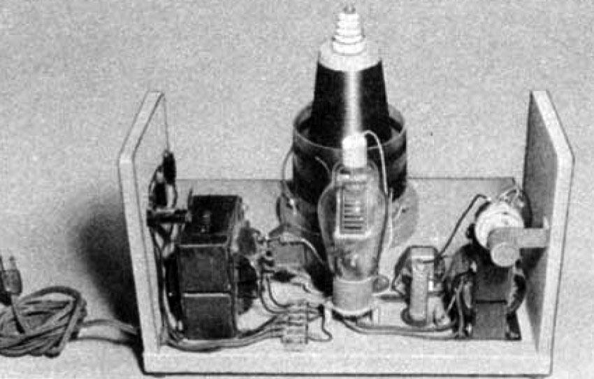
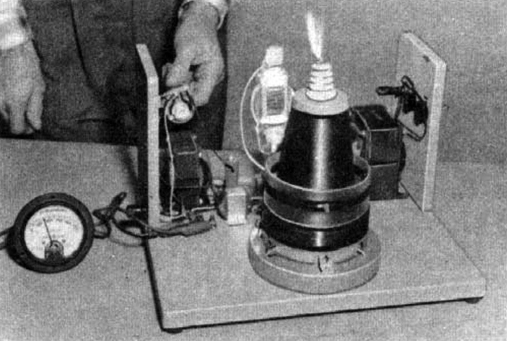
In the photo, page 170, the 1000-v. transformer is at the left and the filament transformer is at the right. The tube socket has been mounted with spacers so it will clear the bottom connections. The rheostat for the grid control is bracketed to the side. Use plastic insulated stranded wire with clamp-on terminal lugs at all screw terminals.
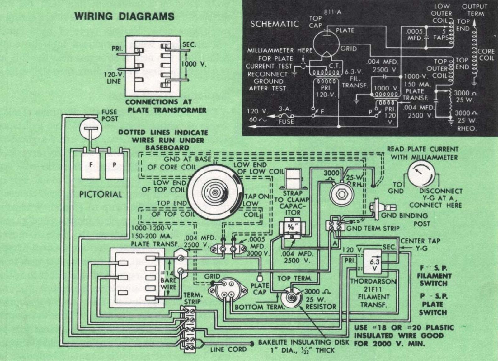
The milliammeter you use to adjust the plate current (top right photo, page 171) should have a scale of 0-300 or more. To hook it into the circuit, remove the center tap of the filament transformer from the ground and connect it to one side of the meter with a clip lead; another lead connects the other side of the meter to the ground terminal. If, when you turn on the power, the meter reads down scale, reverse the leads. To avoid shock, be sure all power is off before you touch any wires or connections around the coil. For maximum safety, you may want to fit a larger plastic tubing over the outer coil.
It's the Combination that Counts
The strong brush discharge shown in several photos indicates a good combination of capacitor value and the best tap on the low outer coil. You can experiment with various capacitor values and taps while adjusting the grid resistance to keep it within the 150-ma. limit for the plate current. When the best combination has been found, solder the lead to the tap selected. You’ll have to scrape the varnish off each tap with a sharp knife and sandpaper before making any connection.
When operating the coil, be sure to turn on the filament switch first and let the tube warm up 15-20 seconds before you flip the plate switch.
Note that a ground post has been provided at the opposite side from the switches. You can ground the coil with a clip lead to a water pipe or radiator. This post may also be required in some experiments requiring both the ground and high-voltage sides of the circuit.
Materials List
| 1 | 811-A tube |
| 1 | Ceramic 4-pin socket with oval mounting flange |
| 1 | 9/16 ceramic plate cap |
| 1 | 2500 or 3000 ohm, 25 watt Ohmite power rheostat with knob |
| 1 | 3000 ohm, 20 or 25 watt fixed resistor |
| 1 | 6.3 v. 6 amp. filament transformer. Thordarson 21F11 or equivalent. |
| 1 | 1000 v., 150 ma. plate transformer. With enlarged enclosure, stand and Stancor PC8414 power transformer (1200 v., 200 ma.), can be substituted, using primary and these taps only |
| 2 | S.P.S.T. bat handle toggle switches with solder lugs, 6 amp. 125 v. |
| 1 | Finger knob panel type fuse mount for 3AG fuses |
| 1 | Box (5) 3AG fuses, slow-blow type, 2-4 amp. |
| 1 | 5-way binding post |
| 1 | Line cord with plug attached |
| 1 | Johnson 135-45 insulator. Use top half only with 2½” 8-32 machine screw |
| 1 | Mica transmitting capacitor .0005 mfd. 3000 v. Type CM65 |
| 2 | Mica capacitors .004 mfd. 2500 v. Type CM60. |
| Note: Values can be from .0002 to .001 mfd. for the CM65 and .002 to .005 for the two CM60s | |
| 1 | Cinch-Jones barrier terminal strip Type 5-140 |
| 1 | Cinch-Jones barrier terminal strip Type 2-140 |
| About 1/4 lb. #32 Formvar magnet wire | |
| About 1/4 lb. #18 Formvar magnet wire | |
| About 1/8 lb. #26 Formvar magnet wire | |
| 1 | 1/8” Lucite tubing 4 1/2” O.D., 3 1/2” long |
| 1 | Plastic conical vase (Carlisle Mfg. Co.) or equivalent. |
| 10 ft. | #33 or 34 Nichrome wire |
| 10 ft. | #18 or 20 plastic insulated stranded hookup wire |
| 4 | 5/8" rubber knob feet |
Note: All above materials can be bought as a kit from Linwood Products Company, Box 186, Wollaston, Mass., for $39.50 (postpaid in U.S.)
Additional Non-Electrical Parts
| 1 | 3/4” plywood 12” X 13 3/4” |
| 2 | 1/2” plywood 5” X 7 1/2” |
| 1 | 3/8” plywood 4” X 4” (cone disk) |
| 1 | Pine or other stock 1” X 6” X 6” (tubing disk) |
| 1 | Aluminum or other sheet metal 1/16” X 5/8” X 2 1/2” (rheostat bracket) |
| 2 | Aluminum or other sheet metal .025” X 1/2” X 1” (tubing brackets) |
| 1 | Aluminum or other sheet metal .025” X 3/4” X 4 1/2” (capacitor clamp) |
| 1 | Perforated aluminum or sheet metal 13 5/8” X 19 3/4” (enclosure) |