Plans
Solid-State Jacob's Ladder
Build this exciting Jacobs’s Ladder and watch electric arcs ascend the ladder and evaporate in space. It works from a clever 12,000-volt power supply.
People have long been fascinated by electric arcs - and perhaps put off by them. They show up as lightning, Tesla coil discharges, and long sparks that sting as you reach for the doorknob on a cold, dry, winter day. This Jacob’s Ladder project turns electric arcs into a dramatic but harmless conversation piece.
If you build this project, you’ll learn how a simple power supply operating from the 120-volt AC line can produce 12,000 volts. In addition to powering the Jacob’s Ladder, the supply can power plasma displays, and it has even powered a light-duty, bench-type spot welder.
Perhaps you would like to know the origin of the term Jacob’s Ladder. The Bible tells the story of Jacob’s dream about a ladder that extended from earth to heaven. Jacob, the son of Isaac, was the father of the founders of the twelve tribes of Israel. Among sailors, however, a Jacob’s Ladder is a long rope ladder that is hung over the side of a ship so the harbor pilot can climb aboard.
Climbing Arcs
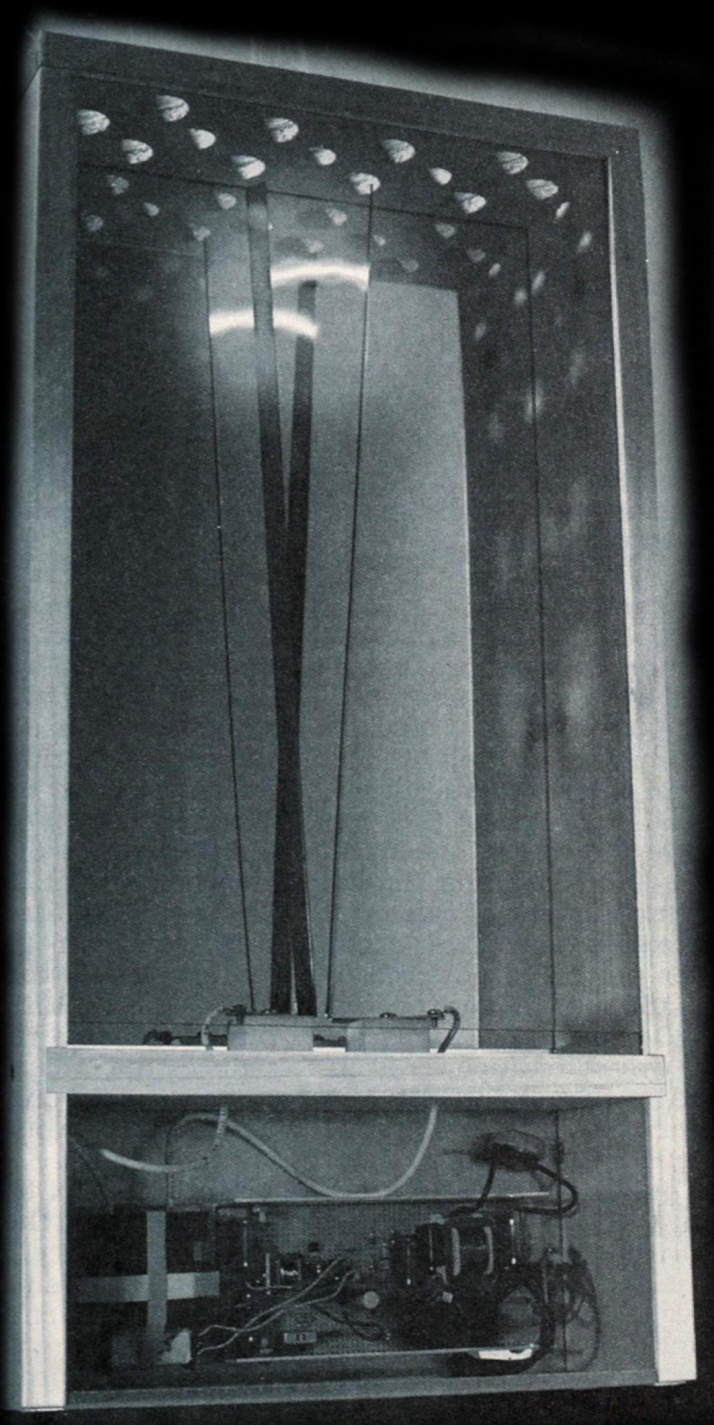
The power supply for this project forms electric arcs across two diverging stainless steel strips mounted in a protective case. The 16-inch long strips are mounted on insulating Teflon blocks to eliminate possible leakage. The stainless steel strips are angled with respect to each other so that the arcs form at the edges of the strips that are separated by about 3/16 inch at their bases, but the strips diverge to a distance of about 2 inches at their upper ends.
The strips form a gap in the secondary winding of the output transformer. After power is turned on, the air dielectric breaks down due to the “almost” short-circuit state across the lower end of the gap, and an electric arc is formed.
As the arc heats up, thermal convection causes the arc to rise up the vee-shaped “ladder.” As the plasma arc ascends the ladder, its length increases, thereby increasing the arc’s dynamic resistance and thus increasing power consumption and heat. This causes the arc to stretch as it rises and extinguish when it reaches the top of the ladder. When the arc extinguishes, the transformer output momentarily exists in an open circuit state until the breakdown of the air dielectric produces another arc at the base of the ladder and the sequence repeats.
The power supply for the Jacob’s Ladder contains circuitry to protect persons and property from electrical shock or fire hazard if the ladder strips should be shorted accidentally when the ladder is operating.
12,000 Volt Supply
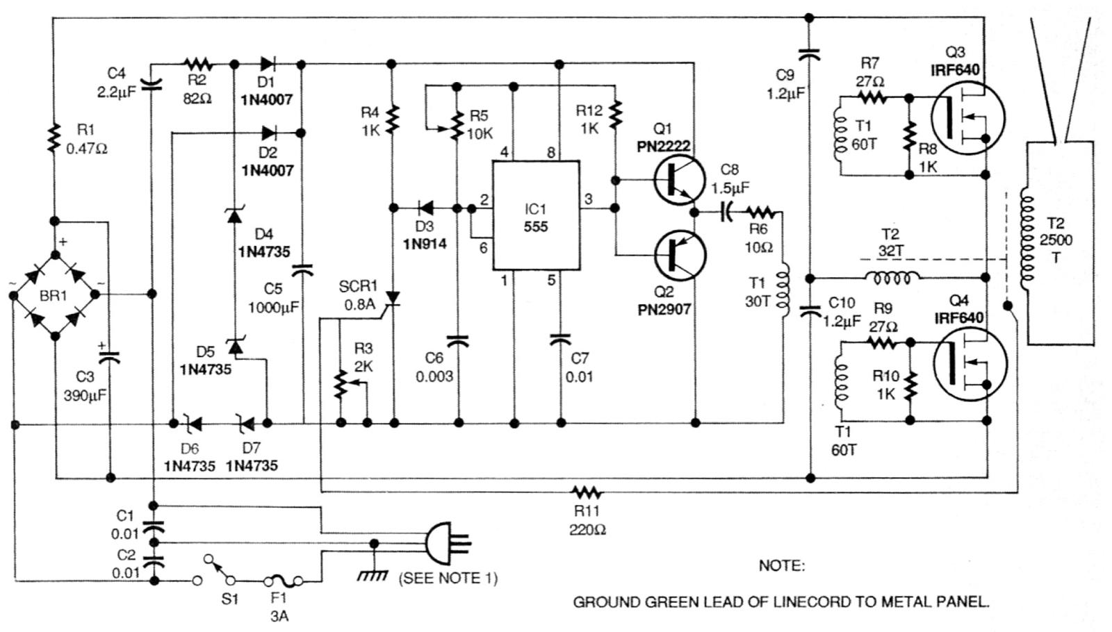
The operation of the Jacobs’s Ladder depends on the current-limited power supply that delivers 12,000 volts at 40 milliamperes from the 120-volt AC line. Refer to the schematic Fig. 1. The full-wave bridge BR1 rectifies the 120-volt AC line input, and resistor R1 limits the DC charging current of capacitor C3 to a safe value. The Jacob’s Ladder project is powered by 150 to 160 volts DC derived from the 120-volt AC line.
The drive circuit power is obtained by dropping the 120-volt AC line through capacitor C4 and current limiting resistor R2. Diodes D1 and D2 alternately conduct only in the positive direction, and their DC output pulses are integrated by filter capacitor C5. Zener diodes D4 and D5 regulate these DC pulses to peak values of 15 volts DC.
Capacitor C4 and resistor R2 present a complex impedance so that most of the AC line voltage is dropped across the reactance. This configuration eliminates the waste of real power and heat losses that would have occurred by dropping the line voltage with only a resistor.
The 555 timer IC1 is configured as a square-wave oscillator. The output frequency of its square waves is determined by the setting of trimmer potentiometer R5 and capacitor C6. The frequency is about 25 kHz for the values of R5 and C6 shown in Fig. 1. Resistor R12 limits the high-frequency setting to an acceptable value. Potentiometer R5 can be used to adjust the circuit’s power output. Increasing the frequency reduces the circuit’s output by increasing the inductive reactance of the transformer leakage inductance.
The output of IC1 on output pin 3 appears at the bases of the current “source,” NPN transistor Q1 and “sink” PNP transistor Q2. The emitters of this transistor pair are AC-coupled through capacitor C8 and resistor R6 to drive the primary of driver-isolation transformer T1. This drive prevents DC from flowing through the primary. Resistor R6 dampens any overshoot that results from transformer T1’s leakage inductance.
This scheme provides a satisfactory source for driving the high gate-to-source capacitance of the two NPN switching power MOSFETs, Q3 and Q4. Transformer T1 is wound on a high-permeability core with as few turns as possible to eliminate leakage inductance.
The gate circuits of MOSFETs Q3 and Q4 contain 27-ohm resistors (R7 and R9) to slow their switching times. This eliminates possible parasitic oscillations that could occur if the MOSFETs were switched at their speed limit.
Output transformer T2 has a half-bridge configuration so that MOSFETs Q3 and Q4 are only subjected to half of the rectified DC line voltage, or about 80 volts. Assuming that the voltage midway between capacitors C9 and C10 is about half of 160 volts (or about 80 volts), when Q3 turns on, the charge on C9 causes current to flow through T2 in one direction.
When Q3 turns off, Q4 turns on, dumping the charge on C10 through T2 in the opposite direction. This drives the magnetic flux of T2 evenly and symmetrically, making full use of T2’s core capability. The primary of output transformer T2 contains 32 turns, but its secondary contains 2500 turns. The ratio of these turns is approximately 1 to 78. When multiplied by the rectified line voltage of 160 volts DC, an output of about 12,000 peak volts is obtained across the secondary.
This 12,000-volt output is the peak open-circuit voltage of the system, and it produces a short-circuit current of approximately 40 milliamperes. This current is limited by the leakage inductance caused by the loose magnetic coupling between the primary and secondary circuits of transformer T2. This leakage inductance can be controlled to some extent by placing air gaps between the cores, changing the reluctance of the magnetic circuit.
Safety Provisions
Because this project is operated from the 120-volt AC line, fault and safety shutdown provisions are included. They are provided by silicon controlled rectifier SCR1 connected as shown in Fig. 1 with its anode in series with diode D3. When the gate current reaches a specified threshold, the SCR is triggered on and latched by the holding current through resistor R4. Trigger pin 2 and threshold pin 6 of IC1 are now clamped to ground, thus preventing oscillation and turning off the circuit.
The signal current for the gate of SCR1 is obtained from the capacitive connection to the actual core of the output transformer T2. This connection is made by winding three to four turns of insulated hookup wire around the core of transformer T2. In effect, it is a capacitive wire pick-up probe. As long as output current is flowing between the output connections of T2, the Jacob’s Ladder will continue to operate.
If, for some reason, one of the output leads (vee strips) is grounded, a return current is forced to flow by capacitive action between the core of transformer T2 through the wrapped-wire pick-up probe. This current then turns on SCR1, shutting down the Jacob’s Ladder.
Building the Circuit
The high-voltage power supply circuitry for the Jacob’s Ladder can be built by point-to-point wiring methods on a 5 1/2 x 2 1/4-inch piece of standard perforated circuit board (holes spaced 0.10-inch on centers) or on a circuit board available from the source given in the Parts List. Drill mounting holes in the four corners of the circuit board before inserting any electronic components.
All of the electronic components with the exception of transformers T1 and T2 are standard, off-the-shelf components available from electronics stores and mail-order distributors. However, the transformers must be custom wound. Both transformers, completely wound and tested, are available from the source given in the parts list. Alternatively, you can wind your own transformers if you have some experience in doing this. Some useful information on winding these transformers and material selection is given later in this article under the heading, “Winding the transformers.”
Refer to schematic Fig. 1 and parts placement diagram Fig. 2. The parts placement diagram gives the approximate locations of all components except for switch S1 and transformer T2, which are off-board components. There is nothing critical about parts placement, and the suggested layout of Fig. 2 is based on keeping interconnecting wiring as short as practical. Be sure to make the gate connection to MOSFETs Q3 and Q4 as short and direct as possible.
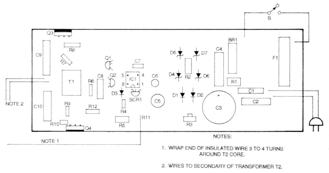
Begin by inserting and soldering all components except MOSFETs Q3 and Q4. Observe the correct polarities for all silicon diodes, (D1 to D3), Zener diodes (D4 and D5) and electrolytic capacitors (C3 and C5). If you wire point-to-point, do not trim the leads of the components until you have made use of as many excess lead lengths as is practical to form interconnections between components.
Then insert the TO-220-packaged MOSFETs Q3 and Q4 close to the outer edges of the circuit board in the locations shown in Fig. 2, with their metal tabs are facing outward. In a later step, the tabs of Q3 and Q4 will be fastened to the sides of a U-shaped channel that functions both as a heatsink and as a support for the circuit board.
Carefully examine all the electronic components on the board to be sure that they are correctly placed and oriented. Examine all solder joints to verify that there are no inadvertent solder bridges or cold solder joints. Make any corrections at this time before proceeding. Then set the completed circuit board aside.
Product Enclosure
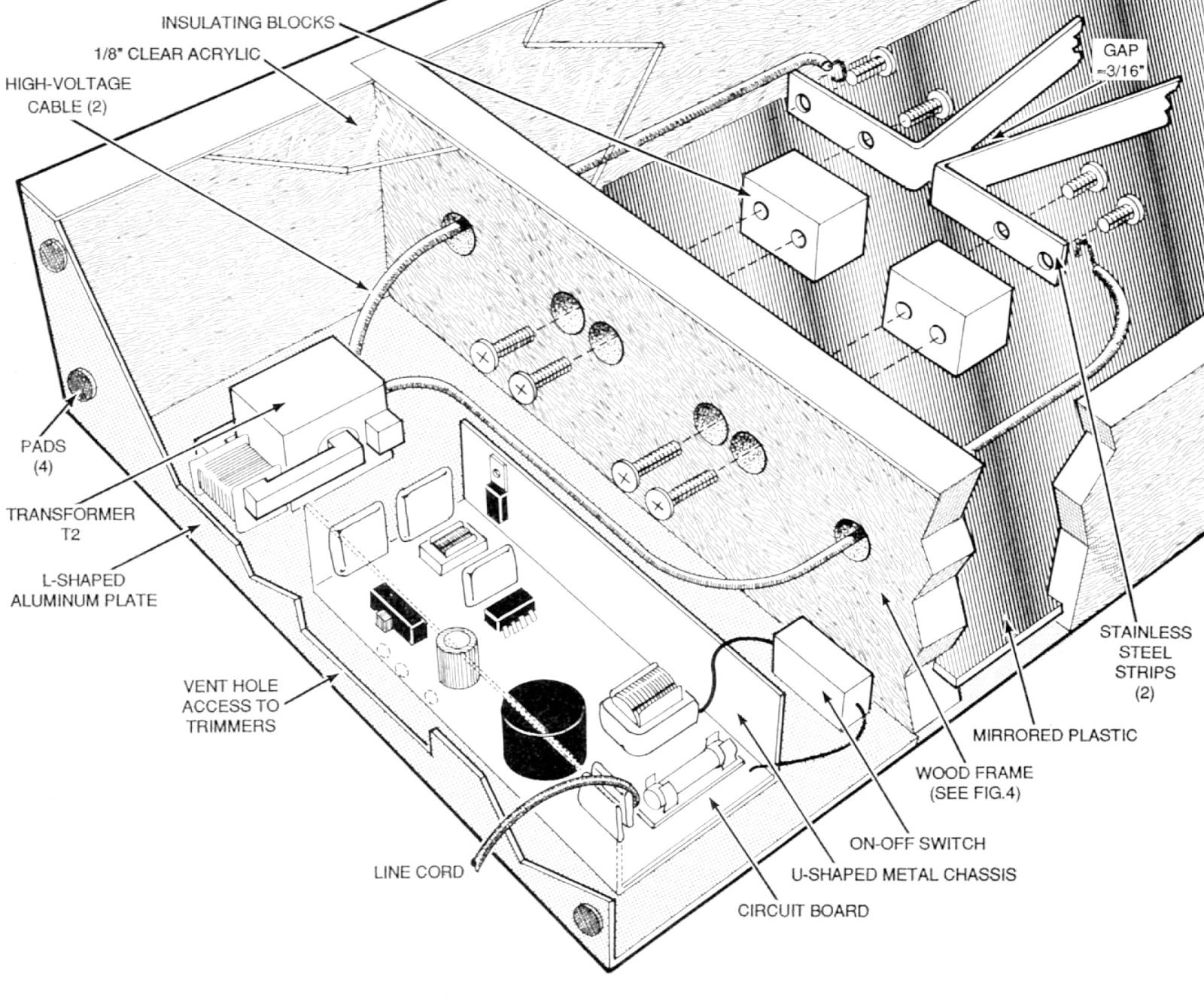
Figure 3 illustrates the author's enclosure for the Jacob’s Ladder project. It was designed to meet two objectives: 1. to meet all reasonable safety requirements by providing adequate insulation between people and flammable materials and the enclosed high-voltage circuitry, while at the same time protecting the circuitry from dust and dirt. 2. to be simple enough to be made by persons with minimal carpentry skills from materials readily available at hardware and home-improvement stores.
Many variations on the author’s enclosure design are possible including changes in exterior and interior dimensions and the substitution of more expensive wood for the framing. However, it is imperative that all provisions for ventilating both the circuitry and the vee “ladder” to dissipate any heat buildup be followed, but make sure that those spaces are not large enough to admit fingers or the small hands of curious children.
The overall case dimensions are 24 x 12 1/2 x 4 inches. The closed H-shaped frame was made from 3/4-inch thick x 4-inch wide soft wood. Slots that are 1/8-inch wide and 1/4 deep were milled 1/8-inch in from each edge of the inside surfaces of the frame members to accommodate protective transparent plastic covers on the front side and a metallized plastic mirror on the back side. (These protective sheets could be fastened directly to the case edges with screws.)
The bottom of the case and the back of the lower circuit/transformer compartment is covered by an L-shaped aluminum plate that serves as the vertical support for the circuit board and output transformer. Holes drilled in the bottom of this plate permit circuit ventilation and access to the on-board trimmer potentiometers R3 and R5. Another hole is formed in the back of the plate for mounting on-off pull switch S1.
Figure 4 provides general information on the sizes and shapes of the principal wood and aluminum parts. Notice the holes drilled in the top member of the frame for cooling the ladder compartment. The author’s prototype frame was made by assembling the wooden frame with screws after the clear 1/8-inch plastic front windows and rear mirror were cut to fit the milled slots.
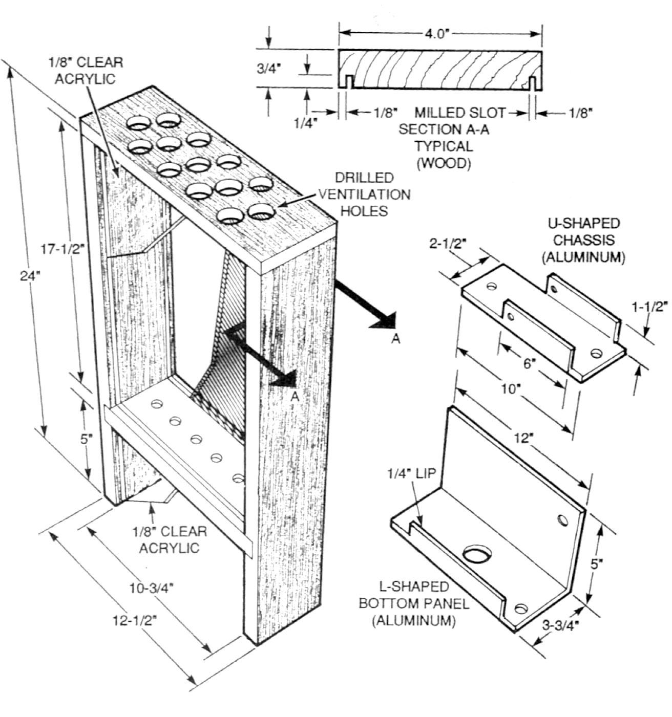
The transparent plastic cover for the ladder compartment was cut 1-inch shorter than the inside dimensions of the frame to provide a bottom opening for ventilation. This ventilation slot is important and should be there regardless of any dimensional changes you might want to make in the frame. The cover for the circuit compartment protects that compartment completely. It is transparent plastic in the prototype so that the circuitry could be seen, but it could be opaque.
Project Metalwork
No hole sizes or location dimensions are given here for the enclosure components. Those are left to the builder’s judgment. Cut and form the U-shaped aluminum channel from No. 22 gauge sheet aluminum, as shown in Fig. 4. Drill holes in both ends of the channel along the centerline. Then, using the drilled holes in the circuit board as a guide, center-punch and drill four holes for mounting the circuit board to the channel. (These can be omitted if you elect to bond the circuit board to the channel with hot plastic glue drops.)
Cut the L-shaped panel as shown in Fig. 4 from No. 22-gauge sheet aluminum. Before bending the front lip or folding the plate, drill 1-inch diameter holes for circuit cooling and access to trimmer potentiometers R3 and R5. Above the fold line, drill another hole for the line-cord, large enough to admit a rubber or plastic grommet, and drill a hole to accommodate chain-pull switch S1. Then bend the flat plate 90° along the fold line and bend up the front lip.
Drill two holes evenly spaced within 2 inches of the ends of the stainless steel “ladder” strips, and bend those 2-inch long sections approximately 90° with respect to the rest of the strips. Note: Stainless steel was selected for the ladder strips because the electric arcs will not cause the strips to oxidize or corrode, and tests showed that stainless steel permits easier starting of the arcs than other metals.
Insulator Blocks
The two metal strips that form the “ladder” must be mounted on insulators that have high dielectric strength. The insulators in the prototype were made from Teflon blocks that measure 1 1/4 x 1 x 3/4-inch high. This material can be drilled and tapped, and it is strong enough to withstand the heat created by electric arcs. Individual Teflon blocks are available from the source given in the parts list.
Project Assembly
With the completed circuit board inserted in the channel, elevated slightly above the bottom of the channel, mark, centerpunch and drill the holes in each side wall for fastening the tabs of MOSFETs Q3 and Q4. Be sure to deburr and perhaps countersink slightly the holes in the channel so that the tabs on the MOSFETs will be clamped securely against the channel walls. Cut and trim the ends of two 3-inch lengths of insulated, stranded linecord to the circuit board, as shown in Fig. 2, to make the connections with the linecord. Insert and solder the ends of the wires on on-off switch S1.
Attach the circuit board to the U-channel with screws and nuts, using several nuts as standoffs to isolate the circuit board from the channel. Align the tabs of MOSFETs Q3 and Q4 with the holes in the sidewalls of the channel, insert insulating mica washers with a film of silicone grease between each tab and the channel walls, and fasten them with screws and nuts.
Cut a 2 1/2-inch square of phenolic laminate or circuit board stock and place it between the base of transformer T2 and the bottom of the channel. Bond the transformer to the insulator and channel base with epoxy or hot glue.
Parts List
All resistors are 1/4, 10%, unless otherwise specified.
R1 - 0.47 ohm, 2 watt
R2 - 82 ohms, 2 watt
R3 - 2000 ohms, PCB-mount, trimmer potentiometer
R4, R8, R10, R12 - 1000 ohms
R5 - 10,000
R6 - 10 ohms, 1/4 watt
R7, R9 - 27 ohms
R11 - 1229 ohmsCapacitors
C1, C2 - 0.01 µF, 1000 volts, ceramic disk
C3 - 390 µF, 200 volts, aluminum electrolytic
C4 - 2.2 µF, 250 volts, metallized polyester
C5 - 1000 µF, 25 volts, aluminum electrolytic
C6 - 0.003 µF, 50 volts, polyester film
C7 - 0.01 µF 50 volts, ceramic disk
C8 - 1.5 µF, 100 volts, metallized polyester film
C9, C10 - 1.2 µF, 400 volts, metallized polyester filmSemiconductors
BR1 - bridge rectifier, silicon diode, 4 ampere, SIP
D1, D2 - 1N4007,1000 volts, 1 ampere, silicon diode
D3 - 1N914, silicon diode
D4, D5, D6, D7 - 1N4735 Zener diode, 6.2-volt, 1 watt
SCR1 - silicon controlled rectifier 0.8 ampere, 200 volt, sensitive gate, TO-92, Teccor EC103B1 or equiv.
Q1 - 2N2222, NPN transistor
Q2 - 2N2907, PNP transistor
Q3, Q4 - IRF640 N-channel power MOSFET, 200 volt, 10 ampere, International rectifier or equiv.
IC1 - 555 timerMagnetics
T1 - driver transformer, 30 turns primary, 60 turns two secondaries (see text)
T2 - output transformer, half bridge, 32 turns primary, 2500 turns secondary (see text)Other components
S1 - switch, SPST, panel-mount, 10 amperes, pull chain
F1 - fuse, 3 ampere, slow-blowMiscellaneous: uit board or perforated board (see text); U-chassis (see text); mirror, metallized plastic (see text); transparent plastic covers (see text); L-panel, (see text) stainless steel strips, 0.060-inch thick, 18 1/2 inches (see text) insulating blocks (see text); high-voltage wire, 15 kilovolt rating, 2 feet; 3-wire power cord with line plug; fuse holder; phenolic transformer insulator (see text); hookup wire; miscellaneous nuts, screws; rubber feet, four; linecord grommet; silicone grease; TO-220 mica washers; solder.
Note: The following parts and kits are available from Information Unlimited, Box 716, Amherst, N.H, 03031; Telephone 603-673-4730; Fax 603-672-5405:
- Kit of electronics components and circuit board, less transformers - $69.50
- Assembled and tested electronic circuit board - $89.50
- Assembled and tested driver transformer T1 - $9.50
- Cores and bobbins for driver transformer T1 - $4.50
- Assembled and tested high-voltage transformer T2 - $24.50
- Cores, bobbins, and potting cap for high-voltage transformer T2 - $14.50
- High-voltage wire (15 KV) - $0.50/foot
- Teflon insulating blocks (2 required) - $5.00
Drill two holes through the wooden frame member between the two compartments, and drill mating holes in the two insulating blocks. Drill a single hole in the opposite sides of each block and fasten the ladder strips to the blocks with screws, as shown in Fig. 3.
Then attach the insulation blocks and strips to the frame member with screws. Fasten the bent metal strips so that they are offset by about 30°, as shown in Fig. 3. The base strips are diagonal across the insulator blocks so that the corner edges are separated by about 3/16 inch. The upper ends of the strips should be about 2 inches apart.
Fasten the channel with transformer T2 and the circuit board to the L-shaped panel with screws and nuts, as shown in Fig. 3. Complete the installation of switch S1 and the line-cord with a grommet, and complete all soldering. Be sure the L-shaped metal panel is hard-wire connected to the earth ground by means of the green wire within the three-wire power cord. Assemble the enclosure with its plastic covers and aluminum base plate. The Jacob’s Ladder is now complete.
Adjusting the Ladder
Carefully examine your work to be sure that there are no inadvertent short circuits or cold solder joints. The circuit is now ready for testing. First, adjust potentiometer R5 as follows:
- Disconnect one end of R1 to Q3.
- Connect an oscilloscope to the Q4 gate.
- Plug in power cord and turn on power.
- Adjust R5 for a period of 40ns so 15-volt squarewaves are symmetrical.
- Shut off power, reconnect R1, and connect the oscilloscope to the Q4 drain. Turn on power. A near perfect squarewave should appear, and it should remain constant as arcs form and reform.
Adjust the ground-fault potentiometer R3 to shut off the circuit if there is ground-fault current.
- Turn off power and set wiper of R3 for maximum sensitivity.
- Disconnect a high-voltage lead from a ladder strip, and connect it to ten 1-watt, 100 kilohm resistors in series. (This simulates a 10 milliampere ground current.)
- Apply power and verify that the circuit shuts down. Turn off power, adjust R3 slightly clockwise. Reapply power until high voltage stays on. Note: Allow time for C3 to discharge before reapplying power or SCR1 will stay on.
Winding the Transformers
Figure 5 is a “footprint” diagram of drive transformer T1 with callouts that can be related to those found on the schematic Fig. 1. The cores and bobbins for this transformer are from Philips (Ferroxcube) Components, Saugerties, NY). The cores are No. E187 made from 3E2A ferrite material. The plastic molded bobbins are Part No. E187PCB1-8. These parts are available from the source given in the Parts List.
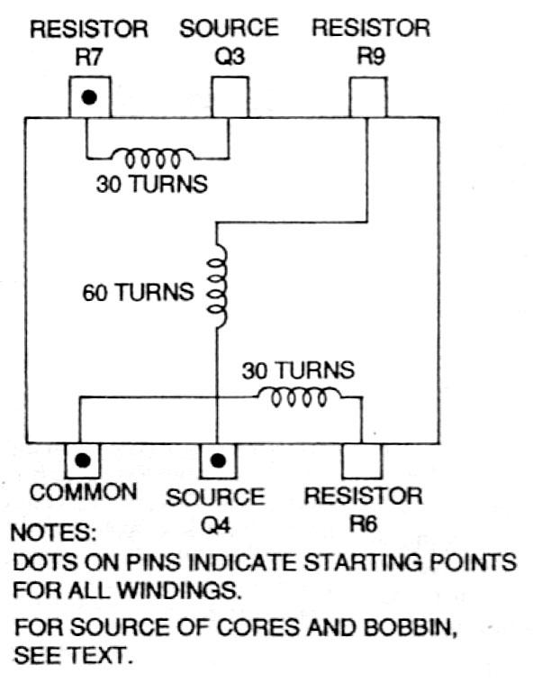
Transformer T1: Wind the first 30 turns trifilar (three wires in parallel) from No. 30 AWG magnet wire and the remaining 30 turns as single wire turns. Solder the ends of the windings to the pins, insert the E-core, and tape the assembly together securely.
Transformer T2: The core of transformer is No. 4162S from Samhwa USA, Chatsworth CA, with matching seven-segment bobbin, cup and primary bobbin. These parts are also available from the source given in the Parts List.
Start winding the secondary bobbin by securing the magnet wire to a pin insulated on the bobbin end and wind between 300 and 400 turns of No. 37 AWG magnetic wire on each of seven segments. Snap the cup in place and solder the output leads. Fill the cup with epoxy or RTV silicone when you are satisfied that the transformer has been wound correctly.
Wind eight turns of No. 30 twisted wires on the primary bobbin and tape the windings in place. Form the air gap of the primary section with 0.005-inch thick Milar tape and form the air gap for the secondary section with 0.010-inch thick Milar tape. Tape or clamp the two sections together with a heavy rubber band.