Nikola Tesla Articles
Transformers
A paper read before the 41st meeting of the American Institute of Electrical Engineers, New York, December. 17, 1889. and discussion thereon. Vice-President T. C. Martin in the chair.
The apparatus by means of which electrical energy of one form may be transformed to that of any other form, few engineers fail to appreciate.
So great have been the anticipated possibilities offered by the application of the modern transformer of alternate current energy that in most cases, in our country especially, has the transformer found immediate application, with but little thought or study of its exact performance. Much experimental work has been done by trial methods to the end that our manufacturers are able to supply transformers that answer for much that is desired practically, with a commercial efficiency that can be made higher than is probably possible by any other transformer of energy.
In electrical engineering, as well as other branches of engineering, for the broad application of one method or another, it is always of the highest importance that the cause and extent of every effect be thoroughly understood with regard to the mutual action and interaction of all forces and materials in relation to themselves, or to energy of one form or another.
It was with a view of obtaining, so far as possible, a clear understanding of all phenomena that take place in the commercial transformer, that the work producing the results here set forth was undertaken. It has not been possible at this time to prepare a paper as complete as has been desired, and we trust that in the near future we may add more data to that which is here presented.
In the outstart of this paper it should be said that the results of the experiments that are here presented were wrought out jointly by Mr. Ernest Merritt, of the department of physics, Cornell University, and the writer. What we had in mind in the work was an accurate determination of the exact performance of the commercial transformer whereby one should be able to derive results and data that should enable all phases of the performances of transformers to be understood clearly, and that should show the requisite principle of proper design. It may be well to state briefly the general method we employed. A single ten-light transformer that had been made and supplied for commercial purposes for incandescent lighting, with 1,000 volts in the primary and 50 volts in the secondary, was selected as a sample for investigation. It probably represented fairly well the average commercial performance of transformers, and might therefore be said to embody, to a certain extent at least, proportions that have proven by experience and experiment to be best for the particular purpose for which it is supplied.
This transformer was operated under the same impressed E. M. F. supplied from the electric lighting plant in which it had been used for supplying incandescent lamps commercially. It was operated with its secondary open and the same closed through one lamp, five lamps, and ten lamps, and under these several conditions the exact instantaneous values of the ever varying primary impressed E. M. F., primary current, and the E. M. F. at the terminals of the secondary were observed. Again under these several conditions the square roots of the mean squares of the above values and of the secondary current were also observed. Then with these observations, the dimensions and the details of the construction of the transformer, many of the facts and performances that the engineer is concerned with, are brought to light.
Naturally the first thing to be considered is the electrical measurements and how they were made. A point on the armature of an alternator always passes a fixed point in its circumference at a time corresponding to a definite value of the varying E. M. F. and current, alike, with regard to these quantities in the primary feeders, transformer, primary or secondary, etc., so long as the conditions remain constant. In our experiments we were only concerned with the values of the E. M. F. impressed at the terminals of the primary, the primary current and the secondary E. M. F., then by changing the position of the fixed point relative to the machine, the rotating point of reference in the armature would pass the new position of the fixed point at corresponding different values for the primary E. M. F., primary current, and secondary E. M. F., with respect to themselves and the position of the armature.
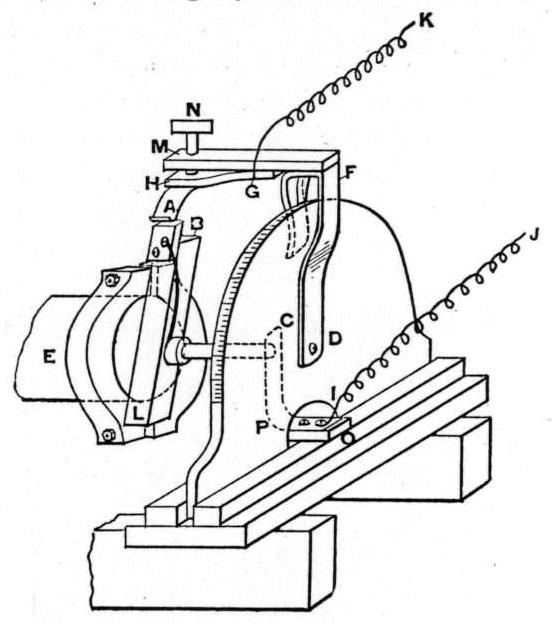
In Fig. 1, B, L, is a prism of hard rubber, bearing a projecting strip of brass, B, that on its upper side is filed to a dull edge. This edge is taken as a fixed point on the armature. An arm, F D, is arranged to rotate about D as a centre, a point that is in line with the axis of rotation of the armature. A semi-circular board of hard wood, attached rigidly to the dynamo frame, serves both as a support for this arm and a circumferential scale whereby the position of the arm may be observed relatively to the machine. The arm is made of brass and given the form shown in the figure. It was bent into a U shape at the top so as to pinch the board and thus remain fixed in any position desired. At the top of this arm is mounted a bar of hard rubber projecting toward the dynamo parallel to the armature axis. On its under side, fastened at G, is a brass strip, a tongue, H, A, of spring brass is attached at the end and at right angles to the brass strip H G, as shown. The position of this part of the apparatus is carefully adjusted so that the point about which the arm rotates is in line with the axis of rotation of the armature and the sharply upward curved end of the tongue H A, just over the edge of the brass strip at B. Then when the armature is rotated the strip H G may be sprung inward radially by turning the thumb-screw N, until the tip of the tongue A is heard to just lightly touch the edge at B as it passes. The arm may then be adjusted by hand so that the tongue will touch the fixed edge on the armature at any desired phase of the primary E. M. F., primary current or secondary E. M. F. and current. Coaxially with the armature a small brass rod is mounted on the bar of hard rubber B L. It is connected metallically to B by means of a wire. At O, on the frame work supporting the semi-circular board, etc., is mounted another piece of hard rubber, insulating and supporting the thin metallic strip, P C, that bears against the above brass rod. G and I then are the terminals of this commutating apparatus.
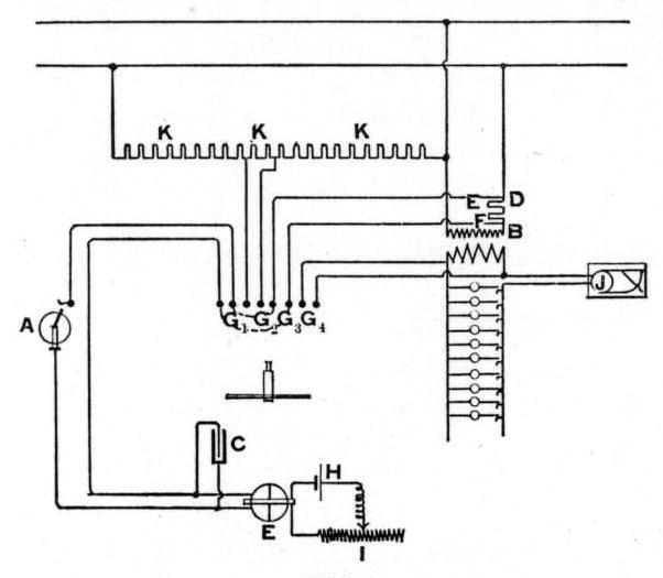
In Fig. 2, E F is a non-inductive resistance in series with the primary of the transformer which is at work. At A is the apparatus described in Fig. 1, and E is an electrometer reading through a wide range.
The terminals of the above non-inductive resistance and those of the electrometer are connected together through the commutating apparatus at A. Then it must be evident to all that the electrometer will become charged with a difference of potential equal to that existing between the terminals of the non-inductive resistance at the instant that the fixed edge on the armature passes the tip of the tongue in the apparatus at A. By reading the indications of the electrometer, therefore, and knowing the value of the non-inductive resistance E F, the value of the primary current corresponding to the particular phase due to the position of the arm in the apparatus at A becomes known. In a similar manner the primary and secondary E. M. F. are observed by changing the connections accordingly at G1, G2, G3, G4. Then the arm is rotated to another position, corresponding to a different phase, and the corresponding values of E. M. F's and current again observed as before. In this manner we proceed at equal intervals, sufficiently near, so that a curve may be determined by the values thus observed at the several intervals, so that the values of the E. M. F'S or currents shall be accurately known at all times throughout a complete period.
A few words with regard to the electrometer at E, are not out of place here. It is the form that the writer devised especially for this and similar purposes. The essential features for an electrometer for these purposes are that it shall have the widest possible range through which it will read with accuracy. Its indications must be unvaried by the absolute potential to which it is subjected as a whole. Its law must be perfectly definite, and it is also desirable that its constant be unchanging.
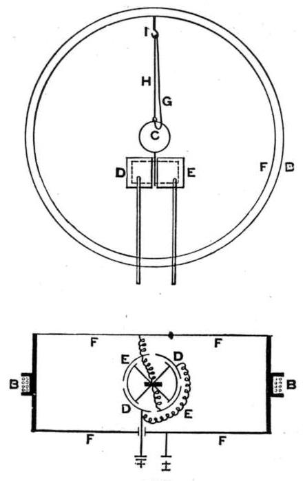
Fig. 3 illustrates this instrument in diagram. It consists essentially of cylindrical electrometer needle and quadrants E. D. To the upper side of the electrometer needle is attached a magnetized steel mirror that acts as a magnet and as a mirror for observing the position of the same. The needle is hung by a single silk fibre, H, from a hook in the top of the case, as shown. Metallic contact from the needle to the case is made by means of a platinum wire, .0002 inches in diameter. This wire is readily provided in the desired form by using the platinum cored silver wire that is supplied by makers of surveying apparatus. It is cut the desired length, and hooks bent into shape at its terminals. By immersing all of it but the hooked terminals in nitric acid, the silver is dissolved away leaving the fine platinum core terminated by the two silver hooks. One end of this platinum wire thus prepared is linked into a hook into the top of the electrometer case and the other end into a small ring formed by a twist of the aluminum wire that surrounds the mirror C. The electrometer case is circular and the above needle and quadrants are arranged so that the magnetized mirror is at the centre of the case, and the needle and quadrants below it. About the case, as the figure indicates, is wound a coil, B B, of rather fine insulated copper wire. The magnetic mirror and this coil then, when the latter is in the magnetic meridian, constitute an arrangement similar to that of a tangent galvanometer. In the electrometer, the needle, case, and one set of quadrants are connected together and form one terminal and the other set of quadrants, being connected together form the other terminal of the instrument, in the manner set forth in the diagram. Thus then, when the electrometer terminals are subjected to a difference of potential, the needle is acted upon by a couple brought about by the electrostatic forces and is deflected from its position of equilibrium. Then, as is shown in Fig. 2, current from a gravity cell in circuit with a suitable rheostat is sent through the coil on the electrometer in such a direction that the needle is brought toward its zero position by the action of the coil, carrying the current, on the magnetized mirror. The current is then further adjusted till the needle stands balanced at zero under the mutual action of the electrostatic and the electromagnetic forces. Under such circumstances then the difference of potential is proportional to the square root of the current.
If we can, as was the case when the measurements here presented were made, consider the E. M. F. of our cell constant, the difference of potential is likewise proportional to the square root of the reciprocal of the total resistance in circuit with the cell. Parallel readings, taken with a standard voltmeter throughout a range varying from 3 to 600 volts, gave identical results showing no deviation from the above law and an unvarying constant. On account of the metallic case and its connection to the rest of the apparatus, the indications of the electrometer are so far as could be observed, entirely independent of the absolute potential to which it is subjected as a whole. In Fig. 2, when contact was made at A, and the electrometer charged to the potential difference to which its terminals were then subjected it was found that considerable of the charge was dissipated by leakage during the course of a revolution of the armature, no matter how good the insulation of the apparatus was. A one-half microfarad mica condenser was then placed in multiple arc with the terminals of the electrometer at C. Then after a few revolutions of the armature the condenser became charged to precisely the same difference of potential existing at the terminals of the electrometer D B, as shown in Fig. 2, when the rotating edge on the armature passed the tip of the tongue on the arm at A.
Under these circumstances the leakage that occured was entirely unobservable as compared to the charge in the condenser during the course of time required for the armature to make many revolutions. Thus arranged then the electrometer would give accurate readings of the primary and secondary E. M. F.'s and primary current corresponding to the connection of its terminals and the position of the arm at A. Again, the square root of the mean square of any of these values could at any time be read from the electrometer by short-circuiting the apparatus at A, and cutting out the condenser at C. For the purpose of obtaining the curve of impressed E. M. F. and the √mean² of the same, twenty-two 50 volt lamps were put in series across the primary circuit. The √mean², of the impressed E. M. F. in the primary was then obtained by reading, by means of the electrometer with the condenser cut out and the commutating apparatus short circuited the √mean² difference of potential existing between each set of two lamps. In this way 11 readings were obtained, the sum of which was the total impressed E. M. F. This served as a calibration of the non-inductive resistance formed by the lamps. At the same time that these observations were made, two lamps were determined upon to be used in all subsequent observations on the total E. M. F. The above observations served then as a calibration for the indications of the two lamps thus to be used. For the constant obtained by the ratio of the above total E. M. F. to the E. M. F. of these lamps taken at the same time always served to deduct the total √mean² or any particular value corresponding to a particular phase of the impressed primary E. M. F. when the same had been observed with regard to the two lamps in the group thus set apart. In this way we avoided the direct measurements of the total impressed E. M. F.
Two 50 volt lamps, E and F, were placed in series with the primary for a non-inductive resistance, and, as previously stated, the √mean², and the values corresponding to any particular phase of the fall of potential through these lamps were observed. This gave a measure of the √mean² or any particular value corresponding to a particular phase of the primary current, when the resistance of these lamps was known at the temperatures to which they were brought by the current. A curve of resistance corresponding to the range of currents through which we used these lamps was determined carefully by Mr. Merritt, at the Cornell magnetic observatory.
In series with the secondary circuit was placed a gravity ammeter containing a few small turns, and correct in its adjustment. It indicated the √mean² in the same way that an electro-dynamometer would have done. The observing of the various values of the secondary E. M. F. required no special arrangement - this was done direct in all cases. Since the secondary was always at work on a circuit possessing almost no inductance, no determinations of the curve of secondary current were made, for it would be found to be so nearly in unison with the secondary E. M. F. and possess all the characteristic variations cf the same. The √mean² of its value was always known from the indications of the ammeter. As a load for the transformer ten 16 c. p. 50 volt lamps were provided that could be turned on and off as desired, and they were at an average distance from the transformer of not more than five feet.
G¹, G², G³, G4, represent, in figure 2, the various terminals conveniently arranged on a switch-board for ready adjustment for any desired set of connections. The adjustable resistance at I, consisted of a plug resistance box, enabling one to get any number of ohms in circuit from 100,000 down. It was very conveniently arranged; but a suitable slide rheostat and a dampened magnet on the electrometer needle would have greatly facilitated the rapidity with which observations could be taken. The mode of procedure was to set the brush at some suitable point of starting out, then corresponding to this point readings of the instantaneous values of primary E. M. F. were made. When lamps were turned on in the secondary, the ammeter in that circuit was also read. The brush was then moved forward to a new position and the above readings repeated. This was continued until we had gone over a complete period of two alternations, then the √mean² readings of the primary and secondary E. M. F.'s and primary current were made. To do this required a period of time covering usually not more than two and one-half hours. Careful observations were made which showed that the insertion of one, two, or three lamps in the primary circuit did not perceptibly change the relation of the primary E. M. F. and current and secondary E. M. F. The indications of the ammeter gave data for correcting for variations of the speed of the dynamo, that throughout was not great.
The following data should be given with regard to the transformer that was used by us:-
Number of turns in the primary coil.................... 675
Number of turns in the secondary coil.................. 35.
Resistance of the primary...................................... 21.8 ohms.
Resistance of the secondary................................... .04 "
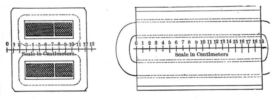
Fig. 4 is furnished with a scale to which it was drawn, so that from it any details as to dimensions of the transformer can be obtained.
The iron discs of the magnetic circuit of the transformer were made one-half millimeter in thickness, their surfaces merely oxidized, so that no special insulating material was provided between the laminations. The total volume of laminated iron used in the transformer was 2,050 cubic cms.
The mean cross-section of the magnetic circuit was 63.3 square cms., and the mean length of the magnetic circuit 30.8 cms.
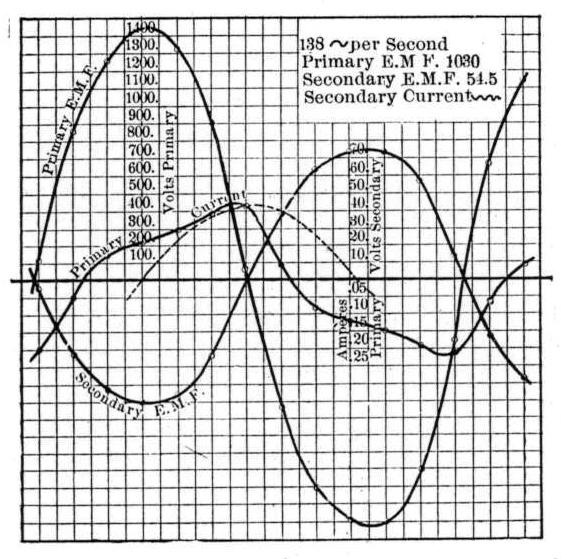
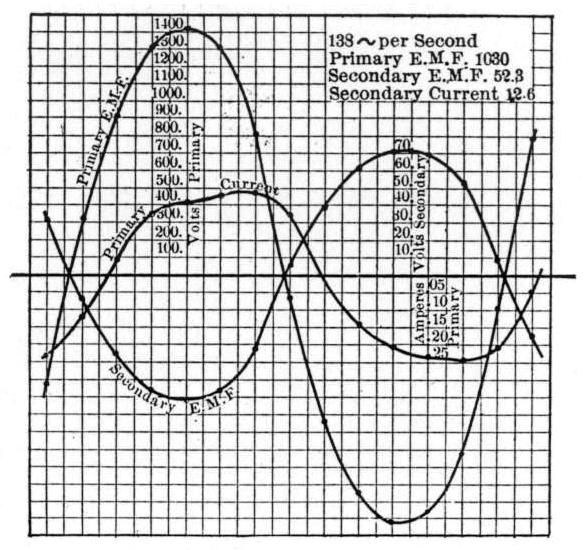
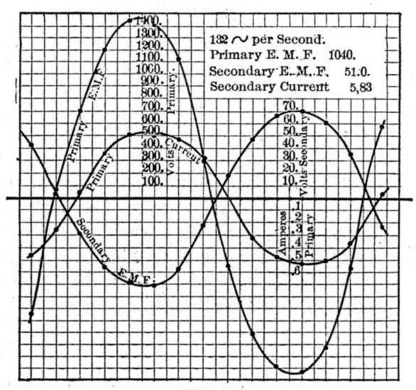
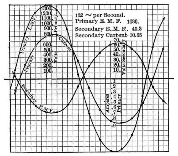
The following observations with the secondary on open circuit and working on one lamp, five lamps, and 10 lamps were made and have been plotted in Figs. 5, 6, 7 and 8. The corresponding curves located by them, drawn in by the scales designated.
Secondary on open circuit.
(See Fig. 5.)
| Brush reading. | Primary. E. M. F. | Current. | Secondary E. M. F. |
| 21 | 119 | .20 | 5.5 |
| 20 | 855 | .05 | 62.7 |
| 19 | 1250 | .07 | 63.4 |
| 18 | 1420 | .11 | 70.7 |
| 17 | 1330 | .14 | 66.8 |
| 16 | 900 | .19 | 46.0 |
| 15 | 45 | .21 | 00.0 |
| 14 | 751 | .04 | 37.8 |
| 13 | 1210 | .08 | 62.0 |
| 12 | 1390 | .12 | 72.0 |
| 11 | 1410 | .15 | 72.5 |
| 10 | 1100 | .18 | 57.8 |
| 9 | 355 | .21 | 14.5 |
| 8 | 645 | .08 | 32.3 |
| 7 | 1130 | .04 | 57.8 |
| Observed √mean2 | 1025 | .14 | 54.5 |
| Calculated √mean2 | 1030 | .147 | 53.5 |
Secondary closed through one lamp.
Secondary on Open Circuit.
(See Fig. 6.)
| Brush reading. | Pirmary E. M. F. | Current | Secondary E. M. F. |
| 28 | 605 | .225 | 31.4 |
| 27 | 330 | .125 | 15.3 |
| 26 | 917 | .048 | 45.2 |
| 25 | 1300 | .179 | 67.6 |
| 24 | 1403 | .215 | 71.7 |
| 23 | 1300 | .235 | 67.1 |
| 22 | 820 | .239 | 43.8 |
| 21 | 132 | .185 | 4.7 |
| 20 | 835 | .000 | 3.9 |
| 19 | 1238 | .151 | 61.5 |
| 18 | 1420 | .215 | 71.7 |
| 17 | 1363 | .238 | 68.4 |
| 16 | 1026 | .246 | 52.7 |
| 15 | 170 | .215 | 9.7 |
| 14 | 793 | .048 | 35.6 |
| Observed √mean2 | 1053 | .196 | 52.3 |
| Calculated √mean2 from curves | 1021 | .190 | 51.4 |
Mean of ammeter readings...........1.26
Secondary closed through five lamps.
(See Fig. 7.)
| Brush reading. | Primary E. M. F. | Current. | Secondary E. M. F. |
| 29 | 956 | .449 | 40.3 |
| 28 | 41 | .250 | 10.4 |
| 27 | 723 | .000 | 28.9 |
| 26 | 1194 | .356 | 54.8 |
| 25 | 1447 | .495 | 69.1 |
| 24 | 1350 | .483 | 67.2 |
| 23 | 1103 | .453 | 57.6 |
| 22 | 293 | .304 | 21.5 |
| 21 | 560 | .000 | 19.8 |
| 20 | 1110 | .318 | 48.8 |
| 19 | 1383 | .464 | 65.7 |
| 18 | 1429 | .511 | 70.0 |
| 17 | 1228 | .500 | 60.3 |
| 16 | 567 | .374 | 24.0 |
| 14.7 | 585 | 0.030 | 23.4 |
| Observed √mean2 | 1050 | .390 | 51.0 |
| Calculated √mean2 from curves | 1036 | .383 | 50.6 |
Mean ammeter reading........5.83
Secondary closed through ten lamps.
(See Fig. 8.)
| Brush reading. | Primary E. M. F. | Current. | Secondary E. M. F. |
| 21 | 138 | .242 | 5.2 |
| 20 | 826 | .276 | 29.7 |
| 19 | 1237 | .642 | 53.5 |
| 18 | 1378 | .795 | 64.0 |
| 17 | 1300 | .821 | 64.3 |
| 16 | 924 | .700 | 51.1 |
| 15 | 63 | .340 | 15.0 |
| 14 | 698 | .188 | 23.7 |
| 13 | 1138 | .587 | 49.0 |
| 12 | 1370 | .810 | 63.7 |
| 11 | 1343 | .844 | 66.0 |
| 10 | 1073 | .771 | 26.5 |
| 9 | 323 | .479 | 26.5 |
| 8 | 590 | .000 | 17.0 |
| 7 | 1117 | .538 | 42.8 |
| Observed √mean2 | 1040 | .631 | 49.3 |
| Calculated √mean2 from curves | 1020 | .634 | 49.3 |
Mean ammeter reading........10.65
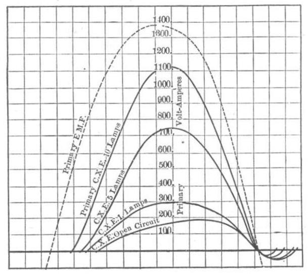
In Fig. 9 are plotted curves deduced from the foregoing observations, that show clearly the rate at which energy is given to the transformer, or that the transformer restores to the circuit at all points of a complete alternation for the several conditions under which the transformer was operated. The curves themselves show so clearly this particular part of the performance of the transformer that nothing more need be said about them, except to give the percentages of the work given to the transformer that is restored to the circuit by it under the several foregoing conditions:-
Open circuit...................................6.8%
One lamp......................... .............3.9%
Five lamps..................................... .96%
Ten lamps...................................... .36%
The above observations and data are ample wherewith to compute the various losses of energy that take place in the transformer under the several loads and under no load, and the deduction of the corresponding efficiencies. These values have been computed and are given in the following table.
Proper corrections have been applied for the two lamps in series with the primary of the transformer.
| Secondary E. M. F.* | Primary watts. | Secondary watts. | Efficiency | Total loss in watts. | Hyster. loss in watts. | Heating Primary watts. | loss. |
| Primary................10.20 | . | . | . | . | . | . | . |
| Secondary, open 52.3 | 96.1 | 0.0 | 0.0 | 96.1 | 95.7 | 0.4 | 0.0 |
| One lamp............52.3 | 159.1 | 64.3 | 41.1% | 94.8 | 93.9 | 0.9 | 0.0 |
| Five lamps..........50.1 | 388.6 | 300.9 | 77.5% | 87.7 | 83.1 | 3.3 | 1.3 |
| Ten lamps...........47.5 | 607.9 | 525.0 | 86.6% | 82.9 | 69.7 | 8.7 | 4.5 |
*The values given in this column have not been corrected for the two lamps in series with the primary for the first three conditions and the one lamp that was used for the last. With 10 lamps, where one lamp was used in the primary this correction amounts to an increase of the secondary E. M. F. of three per cent. On open circuit and one lamp it is negligible and three per cent. increase for five lamps. When this correction is applied the drop of 3.5 volts obtained is what was observed by direct measurement on the secondary.
In Fig. 10 these values have been plotted to scales there indicated, and the respective curves that they determine have been drawn so that one can plainly see the exact performance of the transformer under all loads.
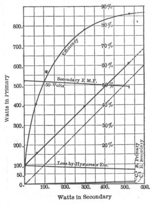
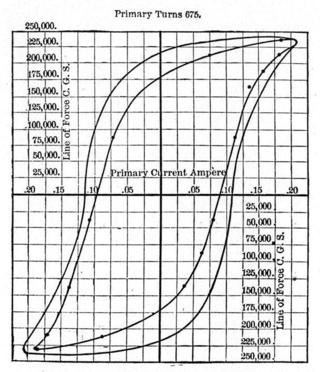
It is interesting to note that this transformer might be loaded to twice its rated capacity and the heating of the coils would still be less than that of the iron, although the heat produced by the iron grows less as the load comes on. Likewise, that its efficiency would not yet have reached its maximum and that it would have a value of 92 per cent. In Fig. 11 the outer curve represents the relation between the magnetizing current in the primary and the degree of magnetization for all points of a complete cycle. The values locating the curve expressing this relation were readily deduced from the observations made when the transformer was working on open circuit. In Fig. 5 the dotted curve represents the curve of primary current that would be found, should Foucault currents be known to be absent, and the relation of ampere turns and magnetization be the same going up as coming down. Then if Foucault currents were present the dotted curve would have a component at a quarter of a period in advance. This would produce a negative lag in the dotted curve. From the position of the actual primary current, it is plainly seen that but a very small component of the above nature is possible, and that the energy that is wasted by eddy currents must therefore be small. The radical departure of the primary exciting current from the approximate sinuous variation of the primary impressed E. M. F. is plainly brought out to be due to hysteresis. From the preceding consideration it is also evident that almost the entire advance of the exciting current and, therefore, the corresponding dissipation of energy, is due to the same cause.
It was thought of much interest to see what amount of hysteresis should be indicated by carrying the transformer slowly through the same cycle of magnetization that it went at the rate of 138 cycles per second when at work on the circuit with its secondary open. Accordingly, by Ewing's method modified for the purpose by Dr. Sumpner, Mr. Merritt determined the inner curve shown in Fig. 11. We regret greatly not to have had time for a careful redetermination of this inner curve, and to carry the magnetization to the same maxima that was done in the transformer when on the circuit. The agreement between the cards would have been more marked even than in Fig. 11.
The assumption made by Mr. Swinburne in bis remarkable and valuable paper on the "Design of Transformers" (proceedings of the British Association, 1889), would therefore, be fully substantiated. Mr. Mordey's experiments, in which hysteresis and Foucault current losses producing a common loss was determined, were performed by cycles of magnetization produced by rotation in which the degree of magnetization did not vary in amount but direction, and cannot be said to throw light on the correctness of Mr. Swinburne's assumption. Some, commenting on this paper, have used Mr. Mordey's results as evidence that these assumptions are wrong.
By a knowledge then of the magnetic properties of the iron, with which a given transformer is to be built, and the methods made use of by Mr. Swinburne, its efficiency is something that can be correctly predetermined.
The importance of making a transformer produce the same E. M. F. at the terminals of the secondary under all loads, asserts itself when it is used for incandescent lighting. In the transformer, under consideration from the ratios of the primary and secondary turns, the E. M. F.'s that they produce, and the variations of magnetization that had to take place through the primary, in order that the same should produce an E. M. F. equal and opposite to that of the primary impressed E. M. F., the magnetization produced through the secondary and the magnetization set up about the primary in its own air space are determined. In the present transformer this "leakage" of magnetism amounted to about 1.2 per cent. When the transformer works on full load, 4.5 times as much current passes through the primary, and the "leakage" of the primary in its own space is 4.5 times as much as on open circuit and becomes 5.4 per cent. This value, together with the small drop due to the actual resistances of the transformer coils, accounts for the fall of 3.5 volts that was observed by turning on all of the ten lamps.
Attention might be called to a similar "leakage" in magnetism that takes place in the secondary circuit. It is plainly brought out in Fig. 8 by the lag of the secondary E. M. F. This magnetic "leakage" producing a self-induction is proportional to the secondary current. The rate of change of this quantity then is proportional to the E. M. F. that it produces. This E. M. F. is, therefore, a quarter of a period behind the secondary current, and results in producing a small lag in primary and secondary currents and secondary E. M. F.
Finally, there is a curious behavior of this transformer that remains to be accounted for. This is the considerable decrease in the loss of hysteresis as the transformer is loaded down, that is not to be accounted for by rise of temperature or the falling off of the magnetization due to the increased "leakage" about the primary in its own air space.
The following reason suggested itself to the writer, why this should take place:-
Mechanical shock has been shown to greatly reduce loss by hysteresis when iron is passed through cycles of magnetization. Since the currents are at all times opposite each other in the two coils of a transformer, strong repulsion occurs when these currents are at a maximum and no force is exerted when they pass through zero. So it follows that they continually keep thrusting each other apart when at work and add to the disturbance of the laminated iron that already exists on account of its changing magnetization. This increasing of the mechanical vibration of the iron, may therefore account for the above-mentioned phenomenon.
On open circuit the maximum magnetization of the iron per square cm. was 3,850 C. G. S.
Loss by hysteresis per cycle per cubic cm., neglecting Foucault currents, .046 watts at 138 ~ per second.
Coercive force per centimetre of the iron, 2.76 C. G. S.
In conclusion, the writer would say that the data here given show for themselves so clearly the advisability of providing some practical means for breaking the primary circuit of the transformer when not in use, that the strong advice of Mr. Swinburne in concluding his paper need not be repeated.
Discussion
Mr. Townsend Wolcott: - Did I understand Professor Ryan to say that the loss of energy is necessarily less where there is mechanical vibration?
Professor Ryan: - It seemed to us to have been so in this transformer; but we are not sure of it.
Mr. Wolcott: - On the supposition that it is so, where does the energy come from? The idea is that the reversal of polarity of the iron absorbs a certain amount of energy in any case; is it not?
Professor Ryan: - The idea, I suggest, amounts to this: that the energy that was taken up in shocking that iron was less than what was saved in the hysteresis. That is, the hysteresis was made less by a greater amount than the energy that was spent in shocking the iron.
Mr. Wolcott: - That is the way I understood it; but is there any explanation why that should be so?
Professor Ryan: - Not that I know of. I have not thought of the matter to any great extent, or further than I have indicated.
Mr. Nikola Tesla: - Professor Ryan has said that the form of the primary current wave departed considerably in certain conditions, from that of the primary electromotive force; and he also stated to what he thought this departure due. I think that this departure of the primary current wave from that of the impressed electromotive force is due, to a considerable extent, to the conditions of the secondary circuit of the transformer, and I regret that Professor Ryan has not shown in the secondary an inductive resistance instead of the lamps. I think that then there would have been found a still greater departure of the primary current from the primary electromotive force. If we close the secondary circuit through a non-inductive resistance, such as lamps, it diminishes the lag of the primary. If we close it through an inductive resistance it increases the lag of the primary. In this way two effects may be produced; first, the primary current wave will depart more or less from that of the electromotive force; second, the secondary electromotive force will lag behind the primary electromotive force, as Professor Ryan has found.
Professor Ryan: - I would like to ask Mr. Tesla how he would produce that inductive resistance in the secondary circuit?
Mr. Tesla: - When you close the secondary circuit through the resistance suppose that you put a coil of wire in the circuit instead of the incandescent lamp.
Professor Ryan: - Would you not be increasing the hysteresis effect in that way? It seems to me that then just what you say ought to follow. Of course it should be understood that stress is laid merely on the fact that there is a certain component at all times flowing to keep up the magnetism; but, aside from that, whatever current passes is merely the opposite of that which passes the secondary circuit?
Mr. Tesla: - You sttud that this departure was due only to the hysteresis.
Professor Ryan: - Suppose that you use hysteresis in the secondary circuit, and thereby augment the irregularities of the primary circuit; is it not, after all, ultimately due to the hysteresis?
Mr. Tesla: - But suppose instead of the incandescent lamp you use a coil of inductive resistance, which would take the same current as the lamp?
Professor Ryan: - When you use any device by means of which you introduce hysteresis in a secondary circuit, do you not greatly augment the displacement of the primary current?
Mr. Tesla: - Of course, as we load the secondary with lamps the primary comes closer and closer to where it ought to be; and I think if you had made a trial with an inductive coil in the secondary circuit instead of the lamps it would have shown some interesting conditions. I believe Professor Ryan stated that the secondary electromotive force commenced at a given point to lag behind the primary electromotive force?
Professor Ryan: - Of course it is gradual.
Mr Tesla: - Have you not noticed, for instance, when this takes place, that it began suddenly?
Professor Ryan: - No; I have not noticed that it began suddenly.
Mr. Tesla: - I should say that when the secondary circuit has a different retardation from that of the primary circuit, then this condition begins. That is to say, if you have a primary coil, and you pass the current through that coil, and you have the secondary circuit closed, you then observe a certain lag of primary current. Now, if you add in the secondary circuit an inductive resistance, you can cause a still greater retardation in the primary. And if you diminish the retardation of the secondary, by inserting lamps, you diminish the retardation of the primary circuit to a greater extent than that of the secondary; thus in both cases causing the secondary electromotive force to lag behind the primary.
Professor Ryan: - I would like to say that Mr. Merritt and I intend to continue our work in this line, but, of course, we wish to vary the circuits upon which we experiment. As soon as we have done this work on the transformers we expect to take up the action of the condenser in all its relations to circuits possessing inductance, and to circuits not possessing inductance; and will test this matter which Mr. Tesla has just spoken of by working a coil in the secondary circuit, instead of a lamp. I think that a great deal is to be brought out in this way; and that one would be able, by careful study, to predict fairly well what would take place by varying the conditions.
Mr. A. E. Kennelly: - The question of hysteresis is of very great importance from every point of view. We know that we can measure the amount of energy which a converter absorbs in a given time; and we can measure also the amount of energy that it delivers during the same interval. We have then to deal with the remainder of energy absorbed by the converter uselessly; and this is to be found, first, in a purely frictional resistance to the current, whereby the energy is transformed into heat; and second, in the effect of the magnetism there is in the current producing the magnetic lag and eddy currents. It is of the very highest importance that we should be able to separate those two forces; and the paper before us gives very important suggestions by means of which we can carry that differentiation into effect. The Foucault currents can be reduced sufficiently by diminishing the cross-section of metal at every point; and we know that in good transformers such currents can be reduced to a minimum; but what we do not know is the quantity of energy which is being absorbed in the hysteresis under the conflicting conditions which are perpetually occurring.
In mechanical engineering we are brought face to face with the wonderful fact that a very large portion of its application and design lies in the general knowledge of the properties of the molecules of iron in the different conditions where iron is used; and the mystery grows when we remember that in electrical engineering it is not so much the molecular properties of iron, in the mechanical as in the electrical sense, which concerns us, and which vary perpetually in every design for apparatus; because, after a piece of apparatus has passed from the stage where the wonder is no longer new, then the question comes: How much can we economize and save out of a given mass of iron and copper? And the question, which is coincident with that, of how much we can save of hysteresis in iron becomes of greater and greater importance.
In hysteresis we have two distinct things to deal with; first, we have the fact that the iron will not return immediately to its previous condition after some magnetic effect has been impressed upon it; and, secondly, that it has a frictional resistance, and cannot instantly obey the reversed force. In all slow working transformers, in all pieces of apparatus where the changes are slow and steady, we can generally neglect what is called the frictional hysteresis due to speed, and simply deal with the static hysteresis; but it becomes of the very greatest importance that we should be able to distinguish more clearly the statical hysteresis from the frictional hysteresis. With regard to the question asked as to the effect of mechanical shocks on hysteresis, I think I may suggest a possibility, namely, that it is simply a question of how the magnetism which has been left after a given impulse can be shaken out; and if you can shake that residual magnetism out by any means you will have that loss by hysteresis destroyed. If you will study the hysteresis chart before us you will see that the area of the curve represents actually the amount of energy which is being consumed or delivered per cycle in the iron through its residual magnetic effect; and if you can prevent that taking place the lag would disappear.
I think the question of the differentiation of the frictional hysteresis from the static hysteresis is one which is well within the reach of experimental methods, and has become one of very great importance; and if words were necessary to recommend its importance still further, is it not enough to consider that apart from practical considerations, it has also a very important scientific rearing; because, by the way in which magnetism acts upon iron (the most completely magnetic substance we find in nature) the more readily can we guess at the principles which underly the whole phenomenon of magnetism; and the more completely can we discriminate the different conditions under which that iron acts, the more truthfully shall we be able to guess at the conditions which nature imposes upon that iron.
Dr. Wm. E. Geyer: - I would like to ask Professor Ryan (if he will be kind enough to turn to the chart showing the primary electromotive force) if any peculiarity was ever noticed about half way up in the curve of the primary electromotive force; a sudden departure from the smooth curve.
Professor Ryan: - Yes; as I think of it now.
Dr. Geyer: - Last May and June there was made, under my general supervision, a very similar experiment, where, however, we used a condenser, and discharged the condenser through a galvanometer, and in that way measured the relative dimensions of the electromotive force. We also got curves which were very smooth indeed (we took points more numerous than those that are drawn on the chart before us), until we got to a point about half way up, where we obtained results which at first were thought irregular and accidental. We skipped that part of the curve and went further up, when again it was extremely regular, until we got down on the other side to about the same height, where again the irregularity began. The irregularity was so persistent that it meant to my mind that it was not a simple accident of the experiment. We then took especial pains to determine points extremely near together just in that region, and persistently obtained a very decided jog in the curve; that is, a sudden upward motion, and a sudden downward motion, at the end of which the perfect regularity of the curve was resumed; and on the other side again there was the same irregularity, and the same jog on the descending curve. I have not found any satisfactory explanation as to the cause of it. If any could be offered by any one present it would be very interesting. I might mention in addition that when these same curves were determined on an open circuit, or on a non-inductive resistance, the irregularities were not noticed. They were only noticed when the transformer was a part of the main circuit.
Mr. Tesla: - May I ask whether the machine was run at a constant number of alternations all the time?
Dr. Geyer: - The machine was run at constant alternations - the regular commercial speed.
Mr. Tesla: - I think if the number of alternations had been varied, greater irregularities would have been observed. I think it will be found that if a higher number of alternations had been chosen, the irregularity would have been more pronounced, until a certain limit was reached. I have run them as high as 15,000 alternations per minute. Where the alternations were very low the irregularities disappeared; but when the same number of alternations, with a longer magnetic circuit in the transformer was employed, they would again appear. So that, as I know that the magnetic lag was varied by the length of the magnetic circuit, I assume that this was the cause of the irregularity. Mr. Kennely has very ably, and rightly, brought up the importance of the study of hysteresis. I think this is a field in which we should all work and achieve considerable improvement: so much so that certain of my experiments have been rather surprising; and in investigating the cause of the lag of the iron we will find the experiments not only of value to investigators but of real value to us practically.
Mr. Joseph Wetzler: - In reference to the remarks made by Dr. Geyer as to the cause of the notch in the curve, it seems to me that it might principally be due to irregularities in the nature of the field. The field poles may have different intensities over different parts of the surface, so that if more strongly magnetic all around the edge than at the centre they would produce an irregular field, which would cause a corresponding effect in the current produced; so that all of the curve would not be regular.
Mr. C. O. Mailloux: - I am inclined to believe that the theory advanced by Mr. Wetzler is the correct one; and I think that the notch in the curve is accounted for by the dynamo, rather than by the reaction of the converter upon the impulse. The fact is, that in a dynamo we never have a uniform distribution of the lines of force, from the very fact that towards the centre, the lines of force are more dense than in the area which is contiguous to the edges. The consequence is that when a coil is approaching the edge of the pole it is approaching a spot where the lines of force are more dense; and after it has passed that spot it finds itself in place where the lines of force are not so dense. It again meets towards the middle of the pole, a place or period where the lines are denser; and again as it comes to the outer edge, a place where the lines of force are not so dense. Now, if you bear in mind the fact that the lines of force are merely the exponents or indicators of the condition of the magnetic medium, showing that there is a highly elastic substance under great stress or tension there, then we may replace those lines of force by elastic substances; and you will find on theoretical reasoning that you would naturally expect that the action of the wire, the moment that it begins to have the current in it, would be to react upon the lines of force and displace them at that point. We know that such is the case in continuous current dynamos, but not with alternating currents. We know that the lines of force are distorted and thrown out of their course by the action of the current in the armature itself. Professor Elihu Thomson has shown by experiment that there is such a crowding effect on the lines of force that, as a matter of fact, the area of the coil, or the contour of the coil, should inclose a smaller area than the area of the pole possesses. I should imagine that the notch in the wave of the impressed electromotive force would be due to the fact that, as the current approaches, it first meets with an obstruction which is too stiff for it to bound over, and therefore immediately cuts the lines of force, creating a high tension, which produces a higher electromotive force. Then we come to a place where the field is more uniform, and consequently we get the action which we would naturally expect - a current more nearly uniform, and at a rate more in accordance with some fixed law. Then as we come to the outer edge we must pass through another crust of the lines of force, and we would naturally expect to find another big break and a slight up-wave. Pursuing the same reasoning you will find that this would take place just exactly as Dr. Geyer has found by experiment; and that the speed at which the alternations occur have a great deal of influence upon that. I should have expected that the lines of force, being like all elastic substances, more brittle to a rapidly acting force, would show that effect more perceptibly at higher alternations than at lower ones.
Mr. Tesla: - Just a word before you pass to another subject. That opposition which was alluded to as occasioned by the dynamo machine might not have its cause in the machine; but that very kind of opposition may exist in the transformer itself; and there is where I believe it does exist. I was sometime ago engaged in some work in getting direct currents from an alternating current; and I found that I was able to produce a preponderance of current impulses in one direction over those of another; and then I found that under certain conditions an opposition appeared, exactly as was stated by Mr. Mailloux in regard to the dynamo machine; and that such conditions can be brought about; and that they depend greatly upon the iron, on the number of alternations, and the length of the magnetic circuit. Imagine, for instance, that you have in the magnetic circuit of the transformer, magnetism in one direction set up; certainly if such magnetism exist it will oppose the passage of a current of a certain direction; and in this way a certain modification of the curve would be brought about.
Mr. Mailloux: - I am very glad that Mr. Tesla spoke of that. I might have gone farther, and said that undoubtedly the same phenomenon would occur in the transformer core itself, and that there would be changes of magnetism there under different circumstances; but inasmuch as he has so much more ably explained it than I could, I need not refer to it again. The only other point I wish to advert to is in connection with some of these curves. I would like to ask Professor Ryan whether he has taken the trouble to follow the concomitant variations of the values of the inductance; that is to say, the instantaneous values that we are supposed to get for the inductance at different variations of the electromotive force; so that we might be able to get a means of comparison between theory and practice. As we all know, the theory of the transformer is one thing, while the practice is another thing, quite remote and apart from it; so much so that the theory, although it is not yet complete, is already behind the times. We know also that that innocent looking symbol designated by L, which represents the inductance in a transformer circuit, does not happen to do so in the transformers which we use in practice. It does so on paper, and in mathematical equations, and also in transformers which have no iron. Now it would have been quite interesting if Professor Ryan had undertaken either to calculate or derive the value given for the inductance; so that we might from that calculate the impedance of the circuit; or, in other words, that spurious resistance factor by which we must multiply the square of the virtual current in order to get the energy that appears in the circuit.
Professor Ryan: - If I have understood Mr. Mailloux's question I will answer it in this way: That if you take what is the accepted theory of the transformer up to date, and which assumes always. I believe, that the relation of the current and magnetism of the iron is the same in an up curve, as it is going down; taking that theory as it has been elaborated, and the suggestion made by Lord Rayleigh about a year ago, that is to say, taking the transformer and observing the relation of the magnetism of the iron corresponding to any particular number of ampere turns going up and coming down, to modify that theory (because it is not always the same), and when you have measured the difference that exists in going up and coming down, you will get exactly the state of affairs that is here found actually to exist. The suggestion that was made by Dr. John Hopkinson in a note published in the Proceedings of the Royal Society a few years ago, made a faint suggestion that if you assume the dotted curve in Fig. 5. and substitute for the same a curve as modified by the values which you obtain through hysteresis, you will get precisely this state of affairs brought out in Fig. 5 as observed for the primary current. One thing more with regard to the method by means of which you can express the exact shape of those curves mathematically, and therefore proceed by means of mathematical investigation, and by means of the impressed electromotive force that we have here given, to find what it is, and what should follow. I will say that Mr. Merritt has carefully analyzed the properties of those curves, and has shown that the impressed electromotive force curve is made up, in the first place of a sine curve in unison with it, and another curve of the third order running along like this; (indicating) of which the equation would be:
E1=1,500 sin Θ - 42. cos Θ + 100. sin 3.Θ + 28. cos 3.Θ;
and finally one of the fifth order; and if we should carry it one further we should find with it one of the seventh order - in odd orders, the even orders having disappeared, or else the magnetism would be heavier on one side than on the other. But matters of that sort are very technical; and I did not think that these curves, representing the constituents of these various curves, would be of much interest, or I should have brought them with me.
Mr. E. G. Acheson: - I understood Dr. Geyer, in speaking of the notch in the curve, to say that he obtained it only when he had the transformer in. That being the case it can scarcely be due to the machine.
Dr. Geyer: - The notches were not obtained when the dynamo was run on an open circuit.
Mr. Kkenelly: - In that case, I venture to say that it must be due either to the magnetic lag or else to a variation in the self-induction. If the processes of self-induction were variable it might be expected. With such variations it is probable that such kinks would follow.
Dr. Geyer: - Am I right in understanding Professor Ryan to say that the efficiency of the transformer was 85 per cent.?
Professor Ryan: - Eighty-six and six-tenths per cent. when working with ten lights in the secondary.
Dr. Geyer: - Was that efficiency tested also in some other way?
Professor Ryan: - No; it merely come in as a secondary matter.
Mr. Mailloux: - It strikes me that Doctor Geyer knows more than he wants to tell us about the transformer tests. I have been told that some extensive work has been going on at Stevens Institute, and it would be interesting to get some information about it.
Dr. Geyer: - What I could say about it has already been published in the Journal of the Franklin Institute. It would have been read before this Institute, except that it came late last year in June, before the summer vacation; and there were so many other papers that it was crowded out. The other tests we made, are very much like those of Professor Ryan, except that we used a condenser as a means of measuring the electromotive force; and we worked a 20 light transformer instead of a 10-light; and the mechanism for taking off the instantaneous electromotive force was slightly different. It is hardly worth while to go through details, as a larger part would be repetition. I have not seen anything in Professor Ryan's charts that differs from those that we obtained. So far as I can see, the results are essentially of the same nature.
The Chairman (Vice-President T. C. Martin) - I understand that Mr. Stillwell, who is Mr. Shallenberger's associate, is here, and if he is moved to speak we would be glad to hear from him before the meeting is closed.
Mr. L. B. Stillwell: - The work that Professor Ryan has introduced to-night is in the general line that we have been working on for two or three years. I had not intended to add anything to the discussion, but there is one point that I might mention which may possibly be of interest, and that is, that we have noticed the point to which Professor Ryan referred in the case of a 10-light transformer, wherein he found that the loss due to the iron decreased as the load is added to the transformer. We have observed that this decrease is more marked in the case of a small one. In a 40-light transformer the iron loss is more nearly a constant; and it seems to me that this fact is in the line of the explanation which has been suggested, as to the shaking out of the magnetism, and the consequent decrease of loss in iron at heavy load in small-sized transformers, as larger ones would be somewhat less liable to mechanical vibration.
If I have understood the diagrams correctly, there is one other point which differs slightly from the observations I have made, in which observations, however, I used the divided electrodynamometer method of measuring the angle of lag. Of course, that method is based upon the assumption that these are sine curves. Applying that method we have found that the lag factor, or cosine, is somewhere in the neighborhood of 70 degrees; and as load is added to the secondary the factor increases more rapidly, than shown by the curves that Professor Ryan has drawn. For example, with live lights on the secondary I have found that the primary and secondary currents are practically 180 degrees apart, the cosine of the angle of lag being about 98 degrees. With that explanation the discrepancy may possibly be due to the irregularity of the primary current, as the diagram by Professor Ryan shows.
I will say that we have also quite recently adopted a method of drawing an accurate diagram of the wave E. M. F. The method is due to Messrs. Scott and Morris, of our laboratory. I have not applied it yet, and have not seen it applied to the purpose of noting accurately the form of wave derived from our ordinary machines, since we have been more especially engaged on new types and various experimental work. The method, however, would afford a very ready means of checking up this observed kink in the curve; and I shall take the trouble to make experiments as soon as possible to throw light on that point. The method in question consists simply in mounting upon the armature shaft a wooden disc with a metallic contact at one point in the periphery, this point being connected with one terminal of a voltmeter, while the other terminal of the voltmeter is attached to one collector of the dynamo. A brush that is connected with the other collector touches the metallic point on the disc once in each revolution. By altering the position of the disc we can get a potential reading on the voltmeter proportional to the electromotive force developed by the machine at any given position of the armature, and moving it gradually through 180 degrees we have obtained surprisingly accurate results - the quantity of current through the voltmeter being large and the time being very slow. The cards I have seen made out in the last week are very accurate, and show perhaps 40 points on a phase diagram. I regret that I have none of the cards here, as they might be interesting in connection with the points brought out.
I would like to add one observation, and it is with regard to the observed efficiency of the transformers. It is, of course, understood that the efficiency of a small transformer is necessarily much less than that of a large one. The conditions heretofore have been such as to compel the use of small transformers, but the tendency as we observe it is very generally towards the use of larger ones. This tendency will do away in a great measure with the implied criticism upon the efficiency of the transformer system.
Dr. Geyer: - I might say that three years ago, when the then existing methods of measuring the efficiency of such apparatus were very uncertain, we resorted to some heroic treatment of it. We stripped the transformer of its outer coil (which I think has not much to do with its efficiency) and the whole transformer was immersed in kerosene oil, and the transformed current was also used up in a calorimeter, consisting of a jar of kerosene; and then we found that as the load was increased the proportion of heat in the calorimeter to the total heat produced, was less and less as the load was made greater and greater.
Mr. Tesla: - Mr. Stillwell has alluded to a method of tracing the wave. I would like to ask the members if any of them have ever made an attempt to find out whether there is a difference when the laminated sheets of the transformer are loose or tight, and if not I wish some one in his idle hours would investigate that; because I have reason to believe that there is a difference when the sheets are tight and when they are loose. Of course, it might be due to the imperfect contact of loose sheets, which would tend to diminish or increase the circulation of Foucault currents.
Adjourned.