Nikola Tesla Articles
Notes on the Design of Electric Motors
In discussing the design of electric motors, it will be necessary to, first of all, consider the relation between the dynamo and the motor. The dynamo may be defined as a machine which converts mechanical work into electrical energy. The motor, when supplied with electrical energy, gives out mechanical work. So far, one is the converse of the other, and the dynamo is said to be a reversible machine.
The extent to which this is true depends very largely on the size of the machine under consideration. This follows from the fact that no matter how bad the design of motor, how weak the field, or how small the magnets or armature, it is sure to run. But a badly designed dynamo—one with relatively weak field-magnets say—will often not excite at all. Or, again, the proportions of armature and field may be relatively correct, but the mass so little that the like result obtains. Why is this, if the dynamo be a reversible machine? It has been shown that the reactions in the dynamo armature are not the same as those in the motor. And it is now generally admitted that the effect of self-induction in the dynamo armature is to increase the lead, while in the motor it tends to diminish it. And Mr. Mordey has pointed out that in the generator the effects of self-induction in the armature windings are opposite to those of the Foucault currents in the core; but in the motor they tend to increase each other.
The writer has had these differences brought under his notice very forcibly in the course of his experience, having been connected directly or indirectly with the design of more than 400 machines, varying in output from 1 h.p. to 100 h.p., and from 20 watts to 70,000 watts.
The chief cause of this difference between dynamo and motor is to be found in the mutual effects of armature and field. Profs. Ayrton and Perry so far back as 1883 showed, both mathematically and practically, that in the motor the magnetism of the armature and that of the field might be added; in fact, the motor effort is proportional to the magnetic strength of both armature and field-magnets, while in the dynamo the field due to the armature, considered as an independent magnet, must necessarily subtract from that of the magnets. These main distinctions occur in the nature of things. Their magnitude at first seems to be considerable; but really the effect depends very largely on the actual dimensions and the relative proportions adopted.
An ideal dynamo has an armature with neither internal resistance nor magnetism per se. The field-magnets alone are the source of lines of force. This condition may be the more nearly attained as the size and weight of the machine be increased. All text-books tell us that the field-magnet should be as powerful as possible, and the armature relatively weak. The exponents of the “reversible theory,” and its corollary, “the better the dynamo the better the motor,” appear to have had more experience of large machines than small ones. And their experimentum crucis necessarily leads them to such views. When such authorities as Hopkinson and Silvanus Thompson, Kapp and Mordey, assert anything electrical, few venture to disagree. But I beg to submit that an extended experience with small and medium size machines would modify their views, especially if weight-efficiency be an object in the design.
Be this as it may, a motor weighing 70 lb. can be made to give a b.h.p. with 70 per cent. efficiency of conversion; but the same machine run as a dynamo would require nearly 50 per cent. more speed to give an output of 746 watts, and even then the efficiency between output and belt-power would be nowhere near 70 per cent. If this be true, and I think it beyond dispute, the theory and corollary require some modification. The approximation to the same efficiency when used as a dynamo or motor becomes the more apparent as the size of the machine is increased; but even up to 50 h.p. I prefer to make certain structural differences in the design of dynamos and motors, particularly if they be series-wound. With shunt machines the difference seems to be less marked owing to the field being nearly constant. If I mistake not, both Hopkinson and Mordey have founded their opinions on observations made from large shunt machines.
Much more might be said on this branch of the subject, and numerous actual experiments might be given in support of my views, but this would digress too much from the object of this paper. With these introductory remarks on the character of motors and their relationship to dynamos, I will pass on to the general design of motors.
There are two broad lines on which motors can be designed. They depend entirely whether weight and overall dimensions enter into the problem. It is only necessary to admit that a powerful armature with many ampere-turns and a relatively weak field will give the same torque as a strong field and a weak armature. Granting this, we can design a motor to give a certain torque independently of the total weight to some very considerable extent. We shall be guided in the proportion of armature and field by the work expected of the motor, by the price allowed for production, by the intended cost of future maintenance, and by the desired life. These two methods of design depend on the point of starting. In the first we take an armature of given size, select a certain surface velocity, and build the field as small as possible to give the desired torque. In the second, a certain type of field iron being determined on, we select an armature of sufficient cross-section to give the required results. The first of these two methods is by far the more scientific, inasmuch as the dimensions of the most costly part of the motor can be made a minimum. The second method, however, will sometimes occur in practice, and it is well to note the possible results of this as well as those of the more general case.
When designing a motor to do particular work the following points should be considered:
- What is likely to be the average torque on the motor and driven shaft?
- Is the motor to run continuously or only for short periods at more or less frequent intervals?
- What variations of load may be expected?
- What will be the maximum torque on the motor shaft?
(1) and (4) will determine the characteristic of the motor and the particular part of the curve at which the average torque shall be arranged to fall.
(4) will determine the size of the shaft and strength of the bearings.
(1) gives us the ratio of the speeds between the motor and the driven shaft.
(2) and (3) determine the limiting safe rise of temperature.
While the winding must be designed to satisfy all the conditions as nearly as may be.
It is not possible within the limit of a short paper to thoroughly analyse the different points to be observed. The general method can alone be indicated, and experience must teach the engineering student the rest. I will roughly run through the several conditions of design, and give such hints as appear likely to be of use.
The first thing to be noted is the torque on the driven shaft. This is not always an easy thing to get at owing to the want of a little scientific nous in the ordinary mechanic. If, however, this be known, it is possible to determine within a few per cent. the required current, and the best ratio of gearing to get a maximum average efficiency from the motor. If this be accomplished, the motor will be a success. If the motor be designed on the assumption of so much horse-power being required, and gearing be accordingly selected, it probably will happen that, though the estimate of power be fairly correct, the motor will be unsuited to the work. The current, and consequently the torque on the motor-shaft, will probably be excessive. The efficiency of the motor will thus be low, and the e.h.p. absorbed excessive, while, further, the speed will be too slow. The obvious remedy would be an increase of the ratio of the intermediate gearing; but if the surface velocity of the motor be correctly designed the increased speed will be too great, and, consequently, introduce other difficulties; in fact, the motor will be a failure—not from any intrinsic fault, but simply because improperly designed for the work.
Daily one comes across machines driven by electricity, steam, air, or water, in which the same fault appears. The speed of the prime shaft is not properly proportioned to that of the main or driven shaft. The consequent loss in possible efficiency is oftentimes not known, or, if suspected, is ignored. This sort of thing did well enough years ago; but addressing a body of educated men who are likely to occupy leading positions among the engineers of the immediate future, I cannot pass it by without protest. I therefore beg to impress on you the necessity of determining in some way or other the actual number of foot pounds required to make one revolution of the main shaft. Your ingenuity will suggest many ways of doing this in most cases.
As an illustration of my point, I will mention the many attempts to run electric tramcars by direct gearing, i.e., without a countershaft. Nearly every firm that has tried the tramcar problem has made the attempt. The last has been the Sprague motor line at Richmond, United States. That the method is unsatisfactory and can be much improved on there is no doubt, for Mr. Sprague has already (October 2nd, 1888) published drawings of a new tramcar involving two motors with countershafts.
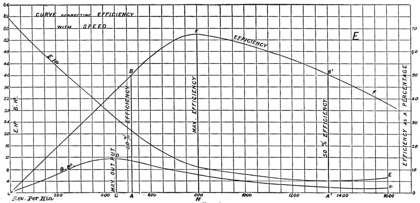
Engineers using electric motors seem to forget that a motor, although very efficient at or about a certain speed, is most inefficient at low speeds (vide Fig. 1).* Too much stress is laid on the property of a motor exerting a maximum torque at starting. It is forgotten that the efficiency is nil under the condition of maximum torque, and that it increases very slowly until the point of 50 per cent. is reached. There are other sides, of course, to the question; but I wish here to strongly emphasise the primary condition of motor design—viz., attention to the torque of motor and main shaft.
Having then determined the torques of the system, the ratio of our gearing is known. Let us suppose that the motor torque be 1/10th that of the main shaft, and that the gearing be accordingly in the ratio of 1:10. We have now to select an armature that will give us this torque at the speed required, satisfying also the conditions of durability, and that the rise of temperature will not exceed a certain limit—say 60 deg. F., above the temperature of the room.
The mathematical expression for the torque of a motor is simple.
Let T be the torque. The output required of the motor at \( n \) revolutions per minute is, say, 1 b.h.p.
Then
\[ T = \frac{\text{B.H.P.}}{2\pi n} = \frac{33{,}000}{2\pi n} = \frac{5{,}280}{n}\ \text{lb. ft.}\quad (a) \]
That is, the moment of the forces tending to turn the armature is equal to \( \frac{5{,}280}{n} \) lb. acting at a radius of 1 ft.
To get the exact pull on the periphery, it will be necessary to multiply this quantity by the ratio \( \frac{1}{r} \), where \( r \) = the mean radius of the armature in feet.
The tangential strain on the wire is therefore
\[ = \frac{5{,}280}{n} \cdot \frac{1}{r}\ \text{lb.}\quad (\beta) \]
This latter quantity is what we require in designing the motor. In order to obtain the desired couple on our armature, we make
\[ T = \frac{Z_a N t C_a}{2\pi}\quad (\gamma) \]
where \( Z_a \) = the number of lines of force passing through the armature, \( N t \) = the number of turns of wire counted all round, \( C_a \) = current flowing in any one coil of the armature—i.e., half the total current—and \( r \) = mean radius of the armature core. It will be noted that the field does not come directly into the question. The function of the field-magnets is only to supply a magnetic field. It will be our care to so arrange the magnets and their windings that the proper value of \( Z_a \) is obtained. This is all that is necessary now. I shall have occasion to comment on this assumption later on when considering the field.
We have now to determine the values of \( Z_a \), \( N t \), and \( C_a \).
\( C_a \) will usually be given us by the condition of supply and the horse-power required.
\( Z_a \) can be determined from the equation \( Z_a = 2 a b z \quad (\delta) \), where \( z \) = lines per square inch, \( a \) = depth of core in inches, \( b \) = the length of armature less the insulation in inches.
Experience alone can tell us the best shape and size of armature core, but since the total cross-section (\( = 2 a b \)) is known no great difficulty presents itself. The depth of core will be mainly determined by the style of winding and the value of T. For a small torque, a small armature and a large number of revolutions will be chosen; for a large torque, a large, slow-speed armature is required. It will be necessary to note that a large cylinder or ring armature of short length is equivalent to a long drum of smaller diameter.
Then, assuming that the core be chosen, \( a \), \( b \), and \( r \) are known. It only remains to substitute these values in (\( \gamma \)) and solve for \( N t \). If the quantities are properly chosen, \( N t \) will have such a value that for a suitable current density the depth of winding will be about 10 per cent. of the core radius for cylinders and 15 per cent. for drums.
If the value of \( N t \) be not a rational one, the dimensions of the core must be altered. A few trials will illustrate this important part of the design, but practice alone can give ease and certainty.
In actual practice the matter is much simplified by previous experience and by fixed sizes of cores. It is then customary to select a wire to suit the current given, and to vary the speed so as to make the magnetic density suitable for the work. This is the crucial part of the whole thing. In other words, the motor is designed to give the required torque at a certain part of the characteristic. This point varies with the shape of the curve and with the conditions of work expected. My meaning will be more easily seen when the field-magnets have been discussed.
The best relative dimensions of armature and field cores is an open question. This is apparent from what has already been said. It depends entirely on the object aimed at. If weight efficiency be the desideratum, the armature must be relatively powerful, and the cross-section of the cores may be made equal, allowing, of course, for the different permeabilities of the iron used. But if cheapness be the principal object, then a heavy field and a small armature are necessary. Speaking generally, the field strength has to be relatively greater as the size of the machine is increased.
The design of the motor field presents some considerable difficulty to the student. There are so many shapes and forms in vogue, and the same end seems to be attained with such opposite forms. With few exceptions, too, even old-established firms are continually changing their patterns, often with no apparent effect other than a weakening of the public confidence, and a considerable needless expense. Indeed, the engineering draughtsman seems to be at his wit’s end to bring out a new design. Yet there is really no ambiguity on the subject. Text-books tell us the best form of magnet is that, cæteris paribus, which offers the least magnetic resistance, with a maximum cross-section and a minimum perimeter. Theory then points to a horseshoe magnet, of circular form and round cross-section. Difficulties of construction, however, render this ideal form too costly, and the matter has to be compromised. It is to this endeavour to balance the advantages of theoretical indication with the necessities of engineering that we owe the numerous types of fields.
The design of the field is, however, not so important with the motor as with the dynamo, and a little consideration will enable the student to determine suitable proportions.
In the first place, the field has to supply a certain number of lines of force to the armature, or is expected to form poles of such strength that, in conjunction with those found in the armature, the necessary torque will be obtained. If gross weight be neglected, and a minimum expenditure of copper be desired, the single horseshoe is chosen. Such machines are common enough, and may be made vertical, horizontal, or inverted. The two first types are the better, since the leakage is less. If a light-weight machine be required, even at the expense of copper, then double horseshoe magnets are used. This type involves twice the number of ampere-turns to give the same strength of pole as the single magnet does; but yet it has considerable advantages. The resultant magnetic field is likely to be more uniform, and less trouble is given by the brushes as a rule. If the armature be of a large diameter—say more than 24 in.—it is better to have a four-pole machine, although the ampere-turns will be double that required with a double magnet, and four times that with a single one, if the same value of \( Z_a \) be taken. The Oerlikon dynamos, for the reduction of refractory ores, are made with six poles, and no doubt a more even distribution of magnetism is gained.
Having selected the form of magnet, the question of length and cross-section of limb arises. Here the criterion is simply sufficient space to wind the wire necessary to give the desired strength of poles and area enough to carry the magnetic flux required.
Here the student finds the first real difficulty. Let us review the position. We know the E.M.F. of supply or the allowed number of volts. The current is also approximately known from the b.h.p. and the assumed efficiency of conversion. The torque of the motor has been determined and expressed in terms of the magnetic flux through the armature iron, the effective cross-section, and the number of turns of wire. The dimensions and shape of the core are also agreed upon. So far it is a physical certainty. The problem now, primarily, is to design a field-magnet which, in conjunction with the armature, will give the required number of lines in the armature core. This is strictly all that is necessary. The question of economy of material and labour spent in the building of the field-magnets cannot be discussed here.
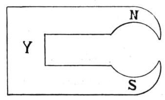
The magnetic flux in the magnets, to give a particular value of \( Z_a \), I believe to be unattainable by direct calculation. Let \( Z_1 \) be the total lines induced at S in a single horseshoe magnet, and assume the lines to pass through the yoke Y and enter the armature at N (Fig. 2). The leakage which occurs all along the windings, and on the neutral part or yoke, reduces the value of \( Z_1 \) to, say \( Z_2 \). But \( Z_2 \) is still further lessened by leakage of lines from N to S outside of the iron or copper of the armature, and the effective number of lines is reduced to, say \( Z_3 \). Now, the ratio of \( Z_1 : Z_2 : Z_3 \) will vary according to the shape of iron, the length of cores, the contour of the winding, and the average density of magnetism. The problem is already sufficiently complex, but yet this is not all. We have to take into account the useful number of lines induced in the armature by its own windings = say, \( Z_4 \). This quantity is usually ignored in text-books, but I know from a large number of experiments, that if we wish to be accurate in our treatment of the subject, this factor must not be neglected. I cannot go into figures, but the importance of the motor-armature, considered as an independent source of magnetism, may be understood from the following considerations:
Take a large series machine designed as a dynamo, having a relatively powerful field and weak armature. Let this be run at such a speed and output that the top of the straight part of the characteristic is just reached. Observe the speed, current, and terminal E.M.F. Then drive it as a motor, using the same number of volts on the terminals, and load the brake till the same value of the current is attained. The speed will usually, I think, be found to be nearly as great as that required as a dynamo.
Next take a smaller machine, designed as a motor—i.e., one with a relatively weak field, etc.—and repeat the experiment. It will probably be found that for the same values of current and terminal E.M.F. the motor speed will be considerably lower.
This variation in the two speeds is due partly to the lead required in different machines when run as dynamos or motors, and also largely to the relative importance of the armature magnetism. Two simple equations will assist the study of the problem. Neglecting friction; let
\( E_d \) be the internal E.M.F. of the dynamo.
\( \frac{\text{B.H.P.}\ 746}{c} \) be the internal E.M.F. of the motor.
\( E_T \) be the terminal E.M.F. both of dynamo and motor.
\( C R \) be the volts lost over the internal resistance of the machine.
\( L_d \) be the value of the reactions of the dynamo armature.
\( L_m \) be the value of the reactions of the motor armature.
It will be necessary to note that \( L_d \) and \( L_m \) will vary with the lead required.
For the dynamo we have—
\[ E_d = E_T + (C R + L_d) \quad \ldots \quad \text{(I.)} \]
For the motor we have—
\[ \frac{\text{B.H.P.}\ 746}{c} = E_m = E_T - (C R + L_m) \quad \ldots \quad \text{(II.)} \]
Now, the speed of the motor varies as \( E_m \), and the speed of the dynamo varies as \( E_d \). It follows, then, that the motor speed should be less than the dynamo by a quantity proportional to \( (C R + L_d) + (C R + L_m) = 2 C R + L_d + L_m \). If the speed of the motor be greater than that given by these equations, \( L_m \), the only quantity that can possibly be varied, must be a factor of importance and, moreover, of negative sign. This means that, in the motor, the armature adds magnetism to the resultant field, and thus increases the value of \( E_m \), and, consequently, raises the speed. In the limit \( L_m \equiv C R \) and \( E_T = E_m \)—see (II.). Even if these values were possible in practice, \( E_m \) would be still less than \( E_d \); so that the relative values of the speeds can only be seen by examination of the ratios \( \frac{E_m}{n_m} \) and \( \frac{E_d}{n_d} \). It will be found with all normal machines that \( \frac{E_m}{n_m} \) is less than \( \frac{E_d}{n_d} \). One must not confound the question of efficiency with these experiments. The efficiency of a dynamo for a given E.M.F. and current varies inversely as the speed, for the torque is clearly proportional to some function of the current, and is nearly independent of speed. The motor efficiency for the same electrical constants varies directly as the speed. In fact, we endeavour to make the dynamo speed a minimum, and the motor a maximum.
In the first experiment, say, in a large Edison-Hopkinson dynamo, the efficiency either as dynamo or motor will not differ much, but I should expect the motor to give the better result by a small percentage. The influence of the armature is relatively small, and the lead very little. The only objection to the machine, considered as a motor, is the weight, and, consequently, increased cost of material for a given output.
In the second experiment the armature is large compared with the field. Hence, the lead as a dynamo will be great—probably 50 deg. at least in a positive direction; as a motor, the lead, if any at all, will be much less, perhaps 5 deg. in the negative direction. The machine will be inefficient as a dynamo, and require a high speed; but as a motor it will be much more efficient, though the speed will not be so great as that required for the dynamo. The second machine will be a good motor—efficient light, and cheap.
This explanation is very rough, but it will help to explain the reason for considering the armature as an independent magnet in motor design. The Oerlikon plant, described in the technical press some six months ago, illustrates the point. The dynamo and motor have armatures identical both as regards the mass and distribution of iron and copper, but the motor field has 7 per cent. less copper and iron than the dynamo, and I know of many installations where proportionately much smaller motor fields are used with advantage.
Many attempts have been made to predetermine the characteristics of dynamos and motors; yet the best seem to be but approximations. From what has already been said, it follows that the difficulty only lies with the number of lines of force in the field. This quantity is indeterminate, chiefly because we have no magnetic insulator. We can get the characteristic of the iron of both field and armature, and we know the resistance of the air space. But we do not know, and cannot as yet predetermine by calculation, the loss of magnetism which will take place over a new type of machine. Mr. Kapp has shown that this leakage is a function of linear dimensions of the machine, and hence varies with every type; indeed, no matter how small the alteration in design the value of the lost magnetism is changed. Practically this presents no difficulty, as only a few types obtain with most firms, and a few simple experiments will determine the number of ampere turns to give any desired result.
Dr. Hopkinson and Mr. Kapp were, perhaps, the first to move in this direction of calculating the ampere turns required in the field to give a definite magnetic flux in the armature. Both methods are well known. But a brief reference will assist us to follow the subject. Mr. Kapp started from a geometrical treatment of the design, and assumed the magnetic resistance of iron to be expressed by a law similar to that of Ohm, and the saturation effect was assumed to follow a tangent function. I have used the Kapp formulæ for many machines, both dynamos and motors; indeed, I think I was probably the first to apply them to motors; but the results are not satisfactory, particularly with large machines. The equations do not take into consideration the leakage in a sufficiently accurate manner, and the ampere-turns have to be increased from 25 per cent. to 100 per cent. above the value given by calculation. The characteristic thus obtained usually rises too slowly, and after cutting the real curve about the point of half-saturation of the field-magnet, does not fall sufficiently rapidly. My experience, I believe, is fairly well borne out by other users of the Kapp formulæ.
Hopkinson starts on a different basis. He determines experimentally the curves of saturation of both field and armature iron, and expresses the magnetic flux in terms of absolute magnetising force (\( 4\pi S i \)) per centimetre length of core. The specific resistance of air is also determined by experiment. So far this is perfectly safe ground. But the characteristic of the machine itself is the summation of the curves of the field and armature iron and the air space, modified by the leakage and the reactions of the armature. Hopkinson has now to resort to experiment to find the magnitude of these disturbing influences, and a good deal of approximation or experimenting is required. Indeed, the method is not applicable to a new type of machine without considerable knowledge of the subject.
Prof. Silvanus Thompson, in the third edition of “Dynamo-Electric Machinery,” gives a method combining both Hopkinson’s curves and Frölich’s equation:
\[ N = N_1 \frac{S i}{S i + (S i)_1}. \]
\( N \) = maximum number of lines in the field-magnet.
\( N_1 \) = lines in field-magnets to give the diacritical value.
\( S i \) = ampere-turns to give \( N \).
\( S i_1 \) = ampere-turns to give \( N_1 \).
But this, again, demands an experimental determination of the leakage coefficient, and does not seem to me to advance the subject much.
Mr. Esson employs a modification of Dr. Hopkinson’s method. Using the saturation curves of the iron and specific resistance of the air as his starting points, and selecting a definite value of \( Z_a \), he determines the number of ampere-turns per centimetre of magnet core to give this value in the armature, neglecting leakage or self-induction. With a known type of machine this method presents great advantages, for the field-winding is given by simple reference to the curves.
Fortunately for us practical men, there is no pressing need of an exact mathematical solution. With a known type of field, machines of any output can be designed with certainty from previous experience and easy applications of the rule of three.
It may be noted that the slope of the characteristic is mainly determined by the resistance of the air gap. The curves of the field and armature iron do not largely affect the general shape till the diacritical points of either be reached. If the field be so crowded with wire that this point be passed, then the characteristic of the machine will bend rapidly.
Before leaving this part of the subject, I will briefly examine the question of pole-pieces.
Judging from the variety of shapes of polar extensions obtaining in machines in the market to-day, there seems to be no little ambiguity on the subject. Some makers use long poles, extending over nearly 160 deg. of the armature periphery. Others cover 90 deg. to 100 deg. Some machines are to be found with long, thin, sharp extensions, whilst some have short, thick, and rounded ends. Each in its way accomplishes a particular end, but only want of knowledge could lead to the extreme proportions sometimes met with. This variety of dimensions in the pole-pieces and extensions arises from an attempted compromise between theory and simplicity of design.
Theory, on the one hand, points to an extended pole-piece if a low magnetic resistance of the air gap be desired. But since there is a tendency for the magnetic density to increase at the extremities of the poles, an undue lengthening of the arc encircled leads to a distortion of the main field. And, further, the position of commutation becomes a line, whilst really there should be some two or three segments on either side on which the brushes may rest without causing sparking or heating of the coils short-circuited beneath them.
Theoretical considerations, then, compel us to shorten the polar extensions, although we thereby raise the total magnetic resistance. This involves, however, no practical loss, for magnetism is cheap, and a few more ampere-turns will compensate for the weakened field.
It is curious to note how the tendency to shorten the pole-pieces has increased during the last 12 months or so. The Manchester dynamo used to have pole-pieces extending over 139 deg. I heard the other day of a Manchester machine with poles not more than 90 deg. in length. Messrs. Paterson and Cooper are also making both dynamos and motors with short poles; so are many other firms.
In some designs there are practical reasons for shortening the poles. If the cores are vertical, it is a convenience to be able to slip the windings over the poles. To attain this, the cores are prolonged and the poles bored out of them, instead of being built up of separate castings. This is applicable to both cast and wrought iron magnets.
Rounded polar extensions are also used in some designs, particularly with high-tension machines. I think this was first done in the Weston dynamos. Speaking generally, for motor pole-pieces I would recommend that the arc embraced be not more than 120 deg., preferably rather less, and that the poles be rounded at all their extremities. The section of the poles should vary about in proportion to the magnetic flux desired. By a careful attention to this point the field may be properly spread over the whole of the coils beneath the poles, and the E.M.F. induced per coil be approximately the same. This is a matter of no little importance in large machines.
The best way of testing the activity of the different coils is the one first used by Mordey, I believe. By a simple arrangement of two movable brushes, the E.M.F. of coils in different parts of the field is successively measured and the result plotted. This gives the differential curve of potential. From this the integral curve may be obtained, or a direct experiment will give the same result. Fix one lead of the voltmeter to, say, the negative brush, and move the other in contact with the commutator through spaces equal to the angular width of one coil, taking readings at each space. These two curves show at a glance the relative activity of the coils and the distribution of the main field. No better method can be devised for showing the exact action of the armature, and the relative advantages of differently shaped poles and polar extensions are at once apparent.
This method is also very useful for showing the difference between the distribution of magnetism in the dynamo and motor field. I have derived considerable assistance from an exhaustive treatment of different machines in this manner. The results obtained are very curious, and serve to explain why it is advisable to make a difference between machines used as dynamos or as motors.
Generally motors are likely to have greater and more sudden variations of load than dynamos, hence the necessity for extra care in designing the pole-pieces. The principal point to be aimed at is to make the position of commutation sufficiently large for the variations likely to occur.
Assuming we have now designed and built our motor on the lines discussed here, it will be necessary to examine the degree of excellence attained. This is best done by brake tests. It will not be necessary to run the motor at a constant potential; indeed, in practice this is often a matter of no little difficulty. Let our motor be series-wound, and designed to run on a lighting circuit of 100 volts. Measure the ohmic resistance hot. Arrange the motor with a Prony or other absorption brake, and put a suitable resistance in series with the windings, so that any desired E.M.F. may be obtained within the limits of supply.
First, run the motor light—i.e., without the brake, at the highest speed required of it, and note the terminal volts and the amperes. Then place the brake in position and screw down the blocks. Take readings with different loads, varying the current by intervals of one ampere, and noting the corresponding volts and speeds. When the maximum load is reached, we have all the data for calculating the performance of our motor. Arrange ten columns with following headings:
| Speed. | Weight | Volts. | Amp. | B.H.P. | E.H.P. | Efficiency. | \( \frac{E}{n} \) | \( \frac{c}{n} \) | \( \frac{\text{B.H.P.}\ 746}{n c} \) |
The first four are filled in from the observations of the test. The b.h.p. is calculated from the speed, the brake load, and the brake constant. The e.h.p. and the efficiency speak for themselves. We have now three columns left. From these we purpose to plot three curves that will show how far our method of design is successful.
The first, \( \frac{E}{n} \), is the terminal E.M.F. divided by the speed obtaining for the particular value of E.
The second, \( \frac{c}{n} \), is the so-called back E.M.F. (\( = E - C R \)) divided by the same value of \( n \).
The third, \( \frac{\text{B.H.P.}\ 746}{n c} \), is really of the same order—viz., a definite number of volts absorbed per revolution in actual work on the brake.
This requires some explanation. Note that the b.h.p. multiplied by 746 gives the available useful h.p. in watts, i.e., a quantity that can be expressed by the symbol C E. We know the current flowing for any load, but do not know the exact fraction of the applied E.M.F. usefully employed for external work. But if we divide the b.h.p. expressed in watts by the known currents, the value of the unknown volts is given. This quantity is divided by \( n \) to reduce it to volts per revolution. The efficiency is thus given us by dividing \( \frac{\text{B.H.P.}\ 746}{n c} / \frac{E}{n} \), or efficiency \( = \frac{\text{B.H.P.}\ 746}{c E} \). We now take a piece of squared paper, and set off the current as abscissæ, and for ordinates the volts per revolution (Fig. 3). Then we plot against the several currents the corresponding values of \( \frac{E}{n} \), \( \frac{c}{n} \), \( \frac{\text{B.H.P.}\ 746}{n c} \). This gives us three curves. Two of these rise from the origin O; but the third, the curve of useful work, starts at that particular value of \( c \), which is just sufficient to overcome the static resistance of the motor. It will be noted that these curves tend to diverge from parallelism as the load increases. They show on inspection two things of great importance in motor design. The height of the ordinates between \( \frac{E}{n} \) and \( \frac{c}{n} \) show the E.M.F. lost over the ohmic resistance of the machine when heated to its normal temperature. The distance between \( \frac{e}{n} \) and the lowest curve \( \frac{\text{B.H.P.}\ 746}{n c} \) shows the E.M.F. lost from all other causes—viz., material and magnetic friction, and by induction. These three curves give at a glance the value of the motor as a converter of energy, and they show not only where the losses occur, but they give the magnitudes. The several quantities are divided by \( n \), simply because it is practically difficult to make a test with constant speed. Since \( n \) is proportional to \( \frac{\text{B.H.P.}\ 746}{n c} \), and is the same for the three ordinates corresponding to each value of \( c \), no error of importance is introduced.
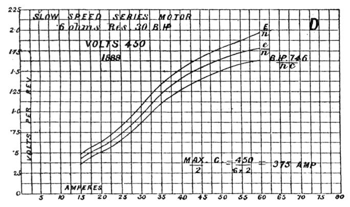
We now can see whether the losses, other than those due to the internal resistance, are excessive. The heat waste is a necessary evil, and can only be reduced within certain limits. The area between \( \frac{e}{n} \) and the work curve can, however, be made very small. In a really well-designed motor this area should always be considerably less than that proportional to \( C^2 R \).
If the losses due to friction and Foucault currents be larger than those caused by the copper resistance, the machine is badly designed. Our motor, however, will not only have a small value for \( C^2 R \), but its other losses will not exceed \( \frac{C^2 R}{2} \).
With these rough notes I close my paper. I may not have told you much that is new, but I hope to have made clear some of the more general difficulties, and to have put the design of motors on a simple engineering basis.
Discussion.
Mr. W. B. Esson: No one regrets more than I do the fact that Mr. Snell himself was not able to be present, but as I have talked over the paper with Mr. Snell, and he is fully aware of what I am going to say, he will probably be just as able to answer my remarks as if he were here. Taking the principle of reversibility, Mr. Snell finds that for a motor there is no critical current—that is, any current above that requires to overcome its friction will make it run. But for a dynamo a current lower than a certain value, called the critical current, is impossible. From this Mr. Snell seems to think that there is something radically wrong in the principle of reversibility, but I think this is a mistake. I made some experiments years ago to ascertain the effects of the reactions of the armature on the field, and concluded that in both dynamo and motor the effects were exactly similar. The case stands thus: Take a series machine and send a certain current through the field-magnets and armature. There is undoubtedly a delay in magnetisation, as pointed out by Ayrton and Perry some years ago, but I do not attach importance to this effect in continuous current machines. Although negligible in these, in alternate machines, however, the magnetic delay becomes enormously important. Well, neglecting this delay, let us send, in both motor and dynamo, the same current through the magnets and armature; it stands to reason that whichever way the armature turns the reaction must be exactly the same, provided that the back lead in the motor is equal to the forward lead in the dynamo. In a motor the only difference is that the armature runs round the other way, the magnetisation of the system and distribution of the field being the same in both cases. In the experiments mentioned, a dynamo was taken with a Gramme ring. This was run to produce several different currents. As a motor it was run at the same speed, and braked until the same currents flowed as were generated when it ran as a dynamo. With the current flowing in the same direction through the machine, the armature revolved, of course, in the opposite direction, the brushes having the tips rounded so that their ends did not turn up with the reversal. If \( V_1 \) and \( V_2 \) are the differences of potential at the terminals of the dynamo and motor, then I found in each case that—
\[ V_1 + C R = V_2 - C R, \]
where C was the current and R the resistance of the machine. I concluded from this that the effect of self-induction might be neglected, and that the delay in the magnetisation of the armature core was also inappreciable.
Now we come to self-induction. In this direction I have been making several experiments lately, and find that in armature cores saturated to 18,000 C.G.S. the effect of self-induction may be entirely neglected. The experiments are made thus: The machine is separately excited, and run without any lead on open circuit, the E.M.F. and speed being noted, also the ampere-turns on the field. We now let a current flow through the machine and note the increase of excitement required to bring the E.M.F. to its previous value—that is to say, the difference of potential at the brushes is equal to its previous value minus the current into the resistance of the armature. There is no lead to the brushes, and therefore any weakening of the field is due to self-induction; and I find that at 18,000 C.G.S. the number of turns required to bring the potential when the current flows up to its former value is inappreciable, while at lower degrees of saturation a certain number of ampere-turns have to be added, which get larger as the saturation is reduced.
Regarding the effect of the armature lines on the field lines, I disagree entirely with Mr. Snell. It is quite true that Ayrton and Perry showed that the effects due to both might be added if the motor were worked with a forward lead, but if I recollect rightly, Ayrton and Perry stated that under usual conditions of work the brushes must have a negative lead. With this you must have a weakening of the field. You cannot have an increase—it is a physical impossibility. I might say that the very reason of a shunt motor governing so perfectly is due to this weakening effect on the field of the armature windings. As the current rises the field is weakened, and the effect is similar to that of a series coil wound on the magnets in the reverse direction to the shunt. For constant speed we require, therefore, no compound winding, but only a particular relation of field to armature. I have seen a motor in which the speed actually increased as the load was put on.
As to the ratio of field-magnet to armature cross-section, it is worthy of note that the cross-section of armature core can be varied very considerably without affecting to any considerable extent the number of lines of force through it. This arises from the fact that the ampere-turns required for the induction through the core is only a fraction of the total ampere-turns for the whole machine. In investigating this my firm constructed two armatures—one had a cross-section equal to ·6 that of the magnets; the other was ·8. The windings were similar, and so was the length; in fact, the only difference was that the hole in the centre of the armature was in one of them smaller. Although the increase in the cross-section was very considerable, the maximum increase in induction due to similar excitements was in the core of larger section only from 5 to 6 per cent. The gain is therefore so small for considerable increase in weight, that I think it is not worth while making two types.
For “useful” lines induced by the current in the armature core, Mr. Snell ought to substitute “useless,” for, as I have already shown, the field is always weakened by them, not strengthened.
I may say that it is a very difficult thing to calculate the magnetic leakage before the machine is built, but it is very simple to measure the leakage afterwards, and from that it is tolerably easy to deduce the leakage in other machines, both of the same and modified types. One point is worthy of remark. Taking the single horseshoe magnet, suppose that in such a machine the ratio of the total lines of force induced in the magnet limbs to those passing through the armature core is 1·32. Now, imagine that you make a mistake in your calculation before the machine is made by assuming the ratio at 1·2, instead of 1·32. The error in the assumed leakage is 10 per cent., but the difference in the E.M.F. of the machine due to having made this error will only be about 2 per cent. The reason of this is that the number of ampere-turns required for the induction in the magnets themselves is fractional as compared with that required for the whole machine.
If the terminal difference of potential = V is the same in both dynamo and motor, their speeds will be in the ratio \( V + C R : V - C R \), the dynamo, of course, being always the higher. I may mention that the efficiency of a motor is always greater than that of a dynamo at the same speed and current, the efficiencies standing in the ratio of \( \frac{E}{E + C R} : \frac{E - C R}{E} \) where E is the E.M.F. generated in each case. Of course it makes no difference to the E.M.F. whether the armature is belt driven or current driven, provided the fields are in each case the same.
One of the chief reasons for the ampere-turns having to be increased over that shown by the calculation is, because in the calculation the demagnetising effect of the armature upon the field-magnets is neglected. This weakening effect is due to the lead of the brushes. In the Manchester machine, for instance, Dr. E. Hopkinson tells me that there are as many ampere-turns of series as of shunt wire, and the chief use of the series wire is to compensate the weakening effect produced by the current flowing through the armature.
Mr. Snell says, referring to the method I use, that I neglect leakage and self-induction. As a matter of fact, I neglect nothing, or rather I only neglect those things that are negligible. Self-induction is negligible, and the leakage I take always at one fixed ratio, an error in this producing, as I have shown, very small effect on the output of the machine.
In conclusion, I again express my regret at the absence of the author. Though my remarks have been of a somewhat critical character, it will be understood, I hope, that concerning all the points of which I have not spoken I have only to utter unqualified praise. They are only the points to which I in some degree take exception that I have called attention to.
* Paper read before the City and Guilds of London Institute Old Students’ Association, January 16, 1889.
** Curve E E is the value of the e.h.p. for the different speeds, the motor running at constant potential. O e is an approximation to the corresponding b.h.p.; and O F F is the commercial efficiency (plotted to another scale). It will be noted that the efficiency increases at first with the speed, and, after attaining a maximum, slowly decreases, having passed through two points of 50 per cent. efficiency.