Plans
Construction and Testing of a Bipolar Tesla Coil
Introduction
I constructed and tested a small bipolar Tesla coil modeled after designs used in physics laboratories in the past. My inspiration for this design came from "Tesla Coils Resurrected," TCBA News 17, no. 2 (April-June), 1998. The featured Tesla coil came from a 1936 Chicago Apparatus Company advertisement. I always liked the bipolar Tesla coil design and decided to build one. This Tesla coil is a variation of the other more common form of Tesla coil wherein the secondary coil is vertical with one discharge terminal (The other terminal is grounded.)
Tesla Coil Construction Details
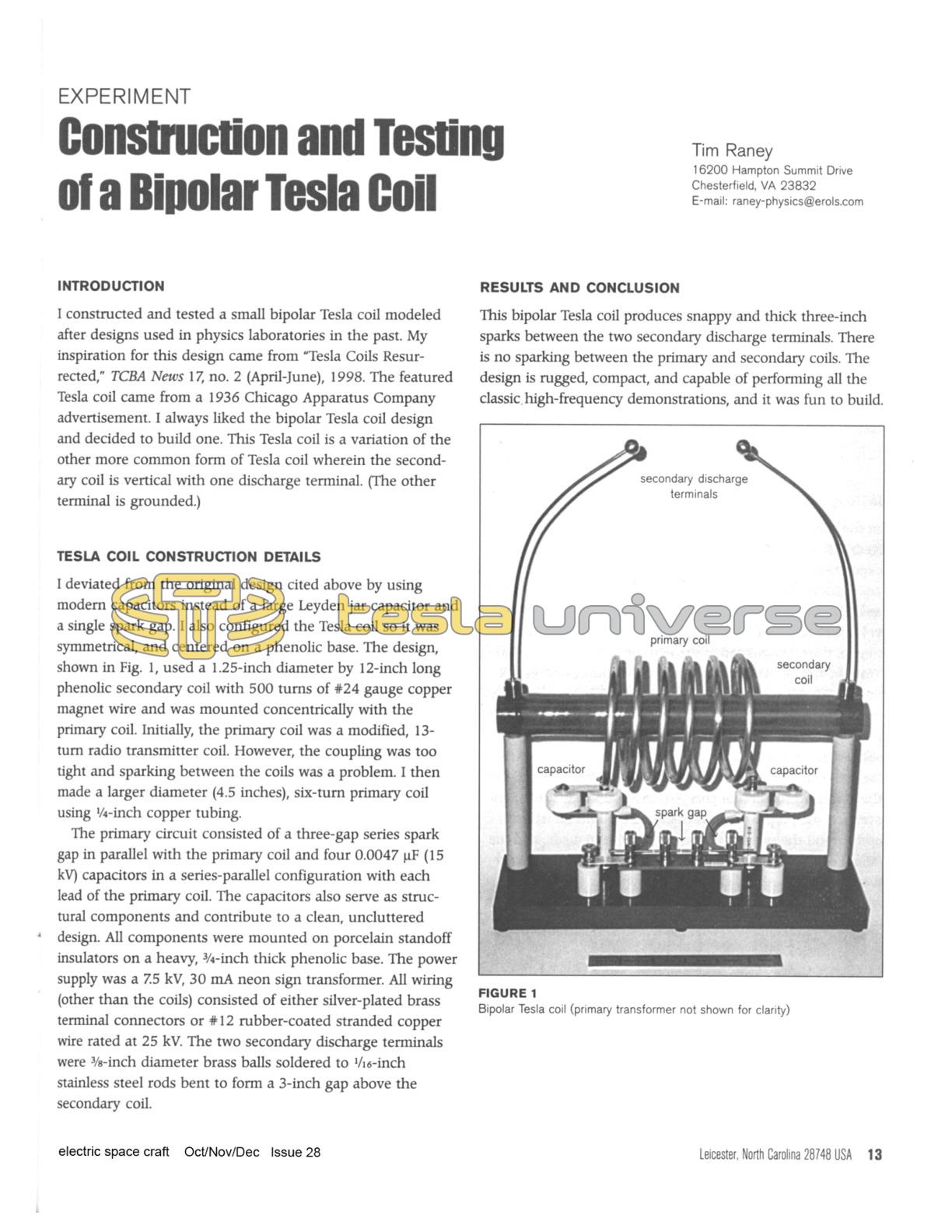
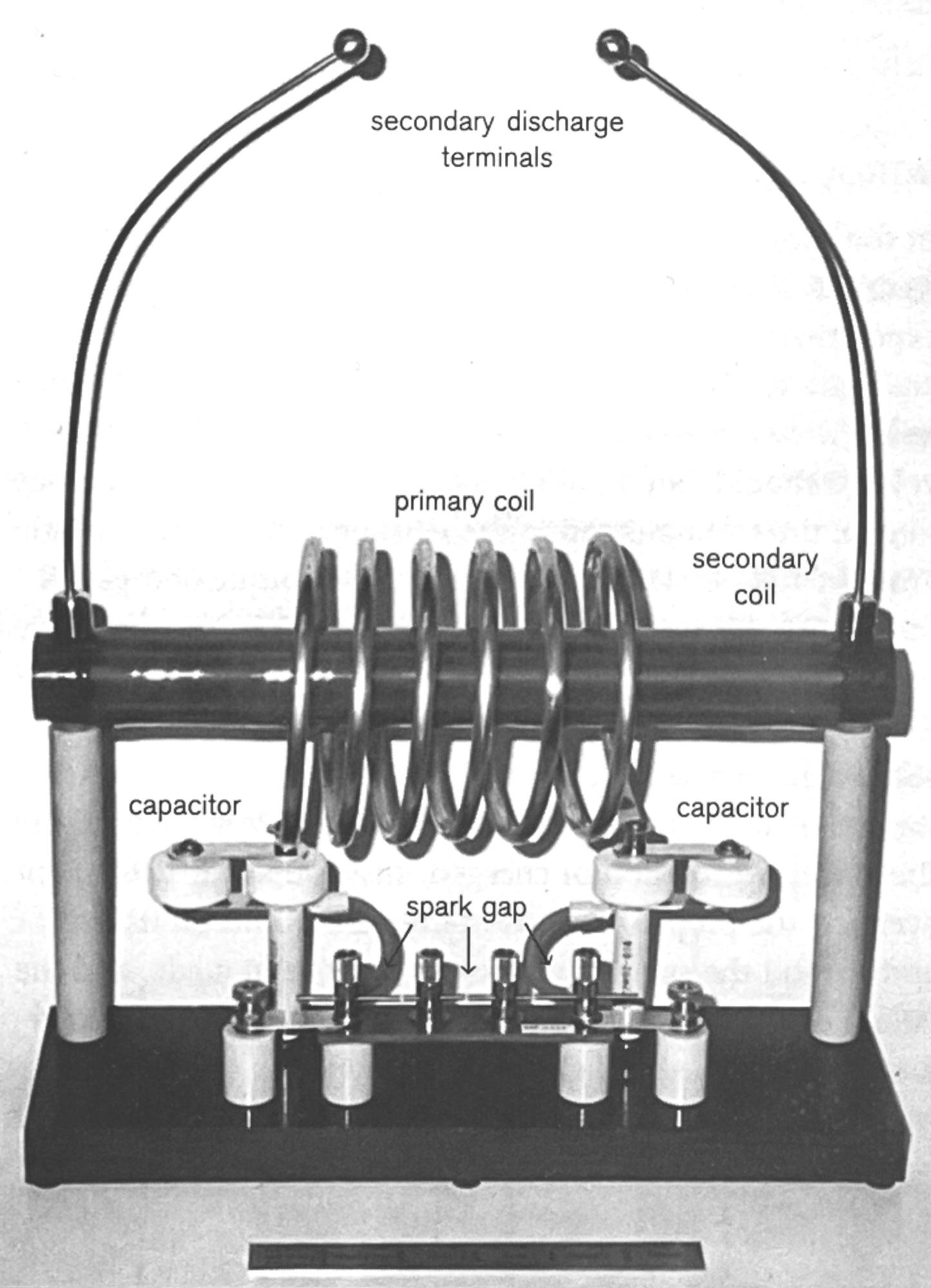
I deviated from the original design cited above by using modern capacitors instead of a large Leyden jar capacitor and a single spark gap. I also configured the Tesla coil so it was symmetrical, and centered on a phenolic base. The design, shown in Fig. 1, used a 1.25-inch diameter by 12-inch long phenolic secondary coil with 500 turns of #24 gauge copper magnet wire and was mounted concentrically with the primary coil. Initially, the primary coil was a modified, 13-turn radio transmitter coil. However, the coupling was too tight and sparking between the coils was a problem. I then made a larger diameter (4.5 inches), six-turn primary coil using 1/4-inch copper tubing.
The primary circuit consisted of a three-gap series spark gap in parallel with the primary coil and four 0.0047 uF (15 kV) capacitors in a series-parallel configuration with each lead of the primary coil. The capacitors also serve as structural components and contribute to a clean, uncluttered design. All components were mounted on porcelain standoff insulators on a heavy, 3/4-inch thick phenolic base. The power supply was a 7.5 kV, 30 mA neon sign transformer. All wiring (other than the coils) consisted of either silver-plated brass terminal connectors or #12 rubber-coated stranded copper wire rated at 25 kV. The two secondary discharge terminals were 3/8-inch diameter brass balls soldered to 1/16-inch stainless steel rods bent to form a 3-inch gap above the secondary coil.
Results and Conclusion
This bipolar Tesla coil produces snappy and thick three-inch sparks between the two secondary discharge terminals. There is no sparking between the primary and secondary coils. The design is rugged, compact, and capable of performing all the classic, high-frequency demonstrations, and it was fun to build.