Plans
Megavolts for Millibucks
by Michael K. Tierney
Student Dean of Engineering
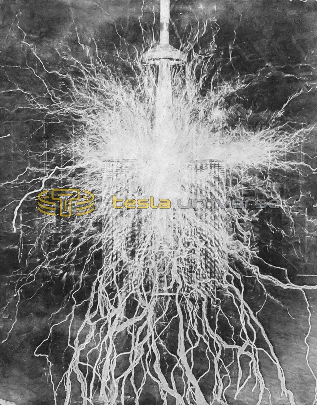
Nikola Tesla, one of our most accomplished yet unacclaimed scientists, experimented with huge coils, which have since come to be known as Tesla Coils. They produced electrical discharges (in his Colorado Springs laboratory) on such a grand scale that they would surely impress Thor or Zeus! Now you can experience the thrill of lightning, but on a much smaller scale of, say a mere 250,000 volts.
With a scaled down version of Mr. T's chunky coils you can create brilliant carona discharges as long as a foot or more, provide a spectacular display of its intense electric field, and neon or fluorescent lamps can be excited as far as five feet away. This Tesla Coil can be built for under $50; however, if a used transformer from a neon lamp can be found, the cost is even less.
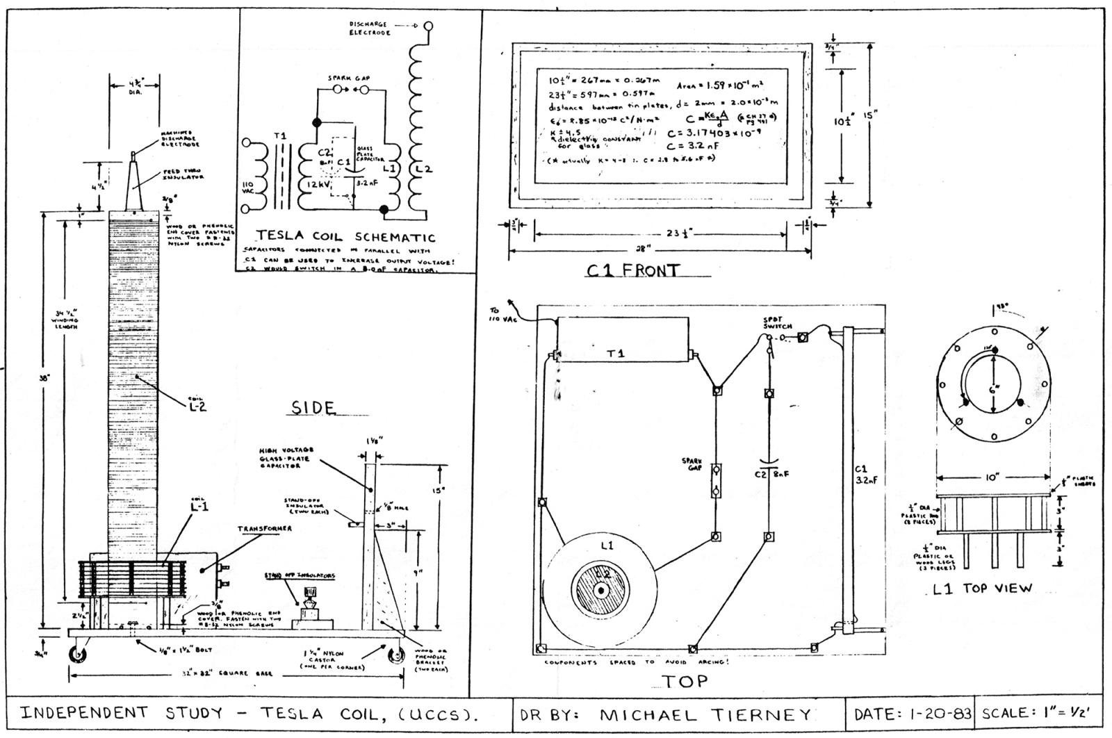
As shown in the schematic diagram, T1 steps up the household line voltage to 12,000 volts. The transformer is the type commonly used to operate neon signs.
A high voltage glass-plate capacitor, C1, is connected directly across the high-voltage secondary winding of T1. The capacitor serves as an energy storage device, charging up to T1's secondary voltage and then discharging in response to the 60-cycle A.C. voltage.
Discharging of C1 is through the spark gap into coil L1. The larger capacitor C1 is made, the larger will be the current through L1. Discharges across the spark gap produce extremely jagged pulses of power which are very rich in r.f. harmonics. The energy-due to the values of the components used is greatest in roughly the 100-k.c. region.
Windings L1 and L2 form an air-core step up transformer, with L1 the primary and L2 the high-voltage secondary. The voltage at L2 will be 75,000 to 250,000 volts depending on the size of C1.
DESIGN AND LAYOUT: The Tesla Coil may be built on a 32" x 32" x 3/4" plywood base to provide adequate spacing between L2 and T1 and C1 so as to prevent arcing. Mount L2 and T1 in separate corners and C1 on the remaining side. If your unit operates at voltages exceeding 100,000 volts, make the base 3' x 3' or greater.
Power to the transformer T1 is the only high-cost component. This "luminous tube transformer" will probably have 2" feedthrough insulators at either end connecting to the high-voltage winding. Primary coil L1 and all connecting leads must be made with high-voltage wire, preferably supported away from the base on 1" ceramic standoff insulators or any more modern equivalent. Test prod wire is ideal as it has flexible rubber insulation with a high puncture voltage rating.
WINDING THE COIL: For the big coil (L2) a phenolic coil form measuring 4 3/4" in outside diameter and 38" in length is suggested. Alternately, cardboard, wood or other insulating materials may be substituted. You can improve these latter types of coil forms by spraying on at least six coats of acrylic plastic spray before winding the wire on them.
The winding itself is done with No. 26 Formvar insulated wire two one pound spools (splice them together and keep the solder joint as small as possible) will give you a 2000 turn, tightly spaced coil covering 34 1/2" of the coil form. There should be extra space between the ends of the winding and the ends of the form.
The lower end of the coil is terminated at a 1" feedthrough insulator installed in the side of the form, the top end of the coil at a 4 1/2" feedthrough mounted to the top end of the form. Make the end covers of wood or phenolic discs cut to the inside diameter of the coil form, and mount them in place with nylon screws (metal screws at the top end would produce corona discharges which could burn the coil form). Alternatively, the top coil cover can be cemented in place with epoxy cement if a sturdy coil form is used. The coil is attached to the base with a 3/8" bolt.
Winding the coil is not as difficult as it appears, and when completed, the entire winding should be sprayed with acrylic plastic for added insulation, moisture protection, and to keep the windings in place. You can't overdo this.
BUILDING THE PRIMARY: As shown in the figure, the form for L1 is made with polystyrene rods and sheeting. While the plastic has excellent insulating qualities and looks good, wood or even cardboard may be used. The form should have an outside diameter of at least 9" to avoid arc-over between L1 and L2. The coil itself (L1) consists of 20 turns of heavy test prod wire.
SPARK GAP: The spark gap is simply two ordinary binding posts mounted on stand-off insulators. In turn, these are mounted on a phenolic base measuring 3/8" x 2 1/4" 6". The electrodes are brass and copper rods with a gap on the order of 1" between them. This distance will vary slightly depending on the size of the capacitor C1.
FABRICATING THE CAPACITOR: The capacitor consists of two 10 1/2" x 23 1/2" "sheets of tin cemented to a 15" x 28" piece of window glass. Actual dimension may be altered to vary capacitance. Although an aluminum foil can be used for the capacitor plates, tin may be used so that connecting leads could be soldered directly to them. If you use aluminum foil, a fairly good connection can be had by making leads of 1/2" wide aluminum foil strips and taping them down to the electrodes. Glass is an excellent dielectric material for this application since it has an extremely high puncture voltage and high dielectric constan. A border of glass is left around the capacitor plates about 1 1/2" wide. The calculated capacity of C1 is approximately 3.2 nF.
TESTING AND OPERATION: CAUTION! Adjustments to the Tesla Coil, and specifically to the spark gap, should be made only when the unit is OFF. Although the output voltage of the Tesla Coil may be on the order of .1 and .3 Megavolts, the current capacity is only hundreds of microamps. This current can inflict a nasty shock and r.f. burns, however.
Use EXTREME CAUTION around the neon transformer. It delivers 12,000 volts at 30 m.a., and this voltage could be lethal under certain conditions. Again, be sure the plug is out when you make adjustments.
To adjust the spark gap, first open it to about 1 1/2"; it will not fire at this point. Gradually move the electrodes together - unplugging the unit each time you adjust the gap until the point is reached where the gap "fires."
To increase the output voltage, simply construct one or two or more capacitors and them across parallel With C1. three capacitors 250,000 volts should be attained; however, with one capacitor and 100 - 150 KV's, a practical and safer demonstration model can be had. A pamphlet of useful demonstrations and experiments is on file at the IEEE Student Branch at UCCS.