Plans
Hybrid Tesla Coil - Solid-State with Spark Gap
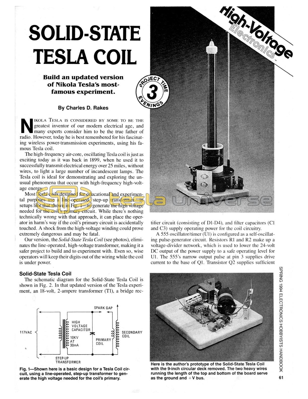
Build an updated version of Nikola Tesla's most-famous experiment.
Nikola Tesla is considered by some to be the greatest inventor of our modern electrical age, and many experts consider him to be the true father of radio. However, today he is best remembered for his fascinating wireless power-transmission experiments, using his famous Tesla coil.
The high-frequency air-core, oscillating Tesla coil is just as exciting today as it was back in 1899, when he used it to successfully transmit electrical energy over 25 miles, without wires, to light a large number of incandescent lamps. The Tesla coil is ideal for demonstrating and exploring the unusual phenomena that occur with high-frequency high-voltage energy.
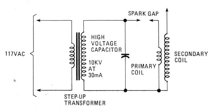
Most Tesla coils designed for educational and experimental purposes use a line-operated, step-up transformer - in setups like that shown in Fig. 1 - to generate the high voltage needed for the coil's primary circuit. While there's nothing technically wrong with that approach, it can place the operator in harm's way if the coil's primary circuit is accidentally touched. A shock from the high-voltage winding could prove extremely dangerous and may be fatal.
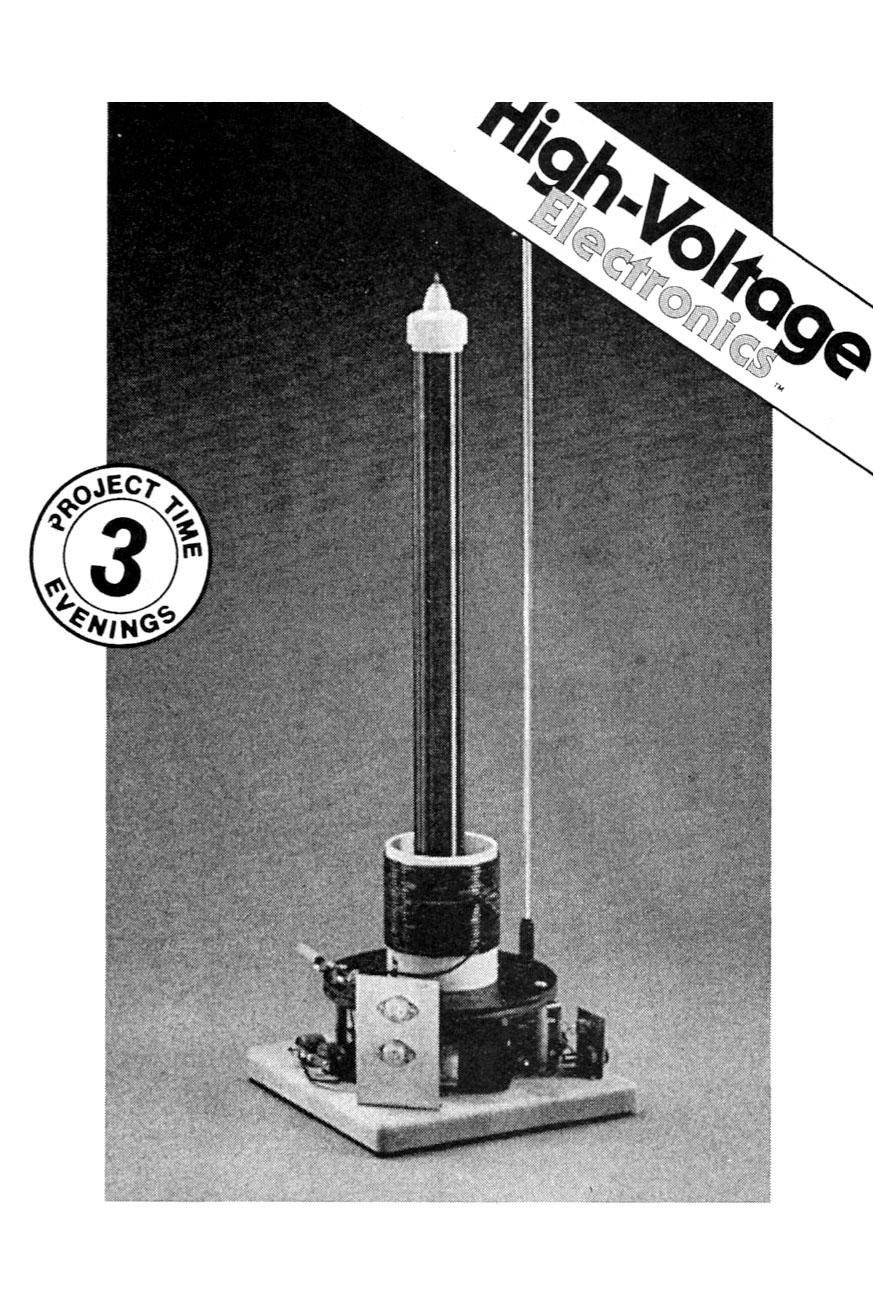
Our version, the Solid-State Tesla Coil (see photos), eliminates the line-operated, high-voltage transformer, making it a safer project to build and to experiment with. Even so, wise operators will keep their digits out of the wiring while the coil is under power.
Solid-State Tesla Coil
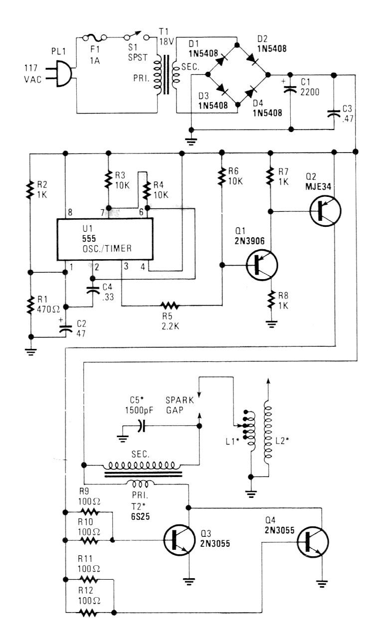
The schematic diagram for the Solid-State Tesla Coil is shown in Fig. 2. In that updated version of the Tesla experiment, an 18-volt, 2-ampere transformer (T1), a bridge rectifier circuit (consisting of D1-D4), and filter capacitors (C1 and C3) supply operating power for the coil circuitry.
A 555 oscillator/timer (U1) is configured as a self-oscillating pulse-generator circuit. Resistors R1 and R2 make up a voltage-divider network, which is used to lower the 24-volt DC output of the power supply to a safe operating level for U1. The 555's narrow output pulse at pin 3 supplies drive current to the base of Q1. Transistor Q2 supplies sufficient current to transistors Q3 and Q4 to drive those components into full saturation.
The primary winding of T2 (an automobile-ignition coil) is connected in series with Q3 and Q4, and across the power supply. Transistors Q3 and Q4 operate like a toggle switch, connecting the coil across the power source at the rate and on-time set by U1.
That high-current pulse generates a rising and collapsing field across the primary winding of T2. The field causes a current to be induced in the secondary winding of T2. The secondary output of T2 is fed across three 500-pF, 10-kilovolt doorknob capacitors (collectively designated C5) that are parallel connected and tied across the high-voltage output of T2 as an energy-storage device. Those capacitors charge up to T1's secondary voltage and are then discharged through the spark gap and the primary (L1) of the Tesla coil, producing higher voltage in the secondary of the coil (L2).
The secret of producing a successful Tesla coil is in the tuning of the primary coil to the natural resonance frequency of the secondary coil. Because variable 10-kilovolt capacitors are about as common as Condor eggs, some other means must be used to tune L1. The simplest method is to tap the primary coil on every turn and select the tap that produces the greatest voltage at the hot end of L2.
Perfboard Assembly
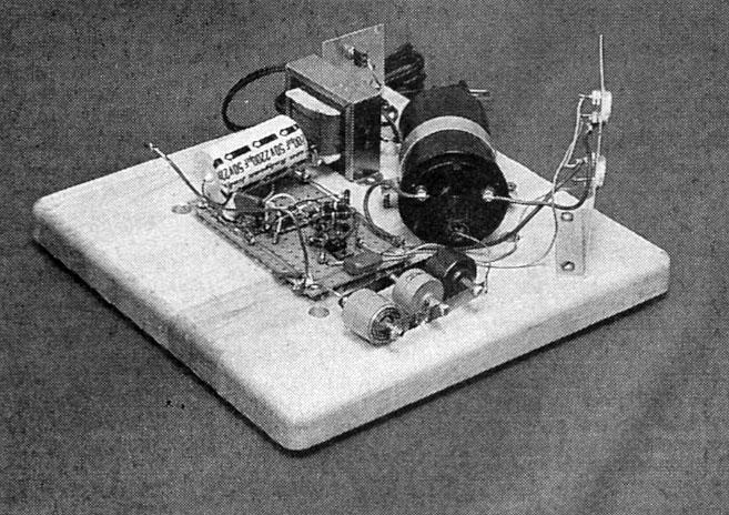
The author's prototype was built breadboard style on an 11 x 11 x 1-inch wooden cutting board (see photos), but any similar non-conducting material (perhaps plastic) will do. The majority of the small components, as shown in the photos, were mounted on a 3 x 5-inch section of perfboard, and point-to-point wiring techniques were used to complete the connections. Refer to the schematic diagram (in Fig. 2) and the photos for wiring and general parts-layout details. Note: Components T1 and T2, C5, Q3 and Q4, F1, and S1 are not mounted to the perfboard (see photos).
Parts List for the Solid-State Tesla Coil
Semiconductors
U1 - 555 oscillator/timer, integrated circuit
Q1 - 2N3906 general-purpose PNP silicon transistor
Q2 - MJE34, ECG197 (or similar) audio-frequency PNP silicon power transistor
Q3, Q4 - 2N3055 NPN silicon power transistor
D1-D4 - 1N5408 3A, 100-PIV silicon rectifier diodeResistors
(All resistors are ½-watt, 5% units, unless otherwise noted.)
R1 - 470-ohm
R2, R7, R8 - 1000-ohm
R3, R4, R6 - 10,000-ohm
R5 - 2200-ohm
R9-R12 - 100-ohm, 1-watt resistorCapacitors
C1 - 2200-uF, 50-WVDC electrolytic
C2 - 47-uF, 25-WVDC electrolytic
C3 - 0.47-uF, 100-WVDC mylar
C4 - 0.33-uF, 100-WVDC mylar
C5 - 1500-pF, 10K-WVDC (three parallel-connected 500-pF doorknob capacitors, see text)Additional parts and materials
F1 - 1-ampere fuse, 3AG
L1, L2 - see text
S1 - SPST miniature toggle switch
T1 - 117-volt primary, 18-volt 2-ampere secondary stepdown transformer
T2 - Automobile-ignition coil (Ford #6S25, or similar) Perfboard, #12 wire, #26 wire, aluminum, Fahnestock clips, spacers, solder, hardware, etc.
Figure 3 shows the positioning of the perfboard and off-board components on the baseboard. Mount the fully-populated perfboard assembly to the baseboard using four 1/4-inch plastic spacers and wood screws. The location of the sub-assemblies on the baseboard isn't too critical, so long as the general layout is followed. Keep all wire leads as short as possible, especially around the high-voltage circuitry.
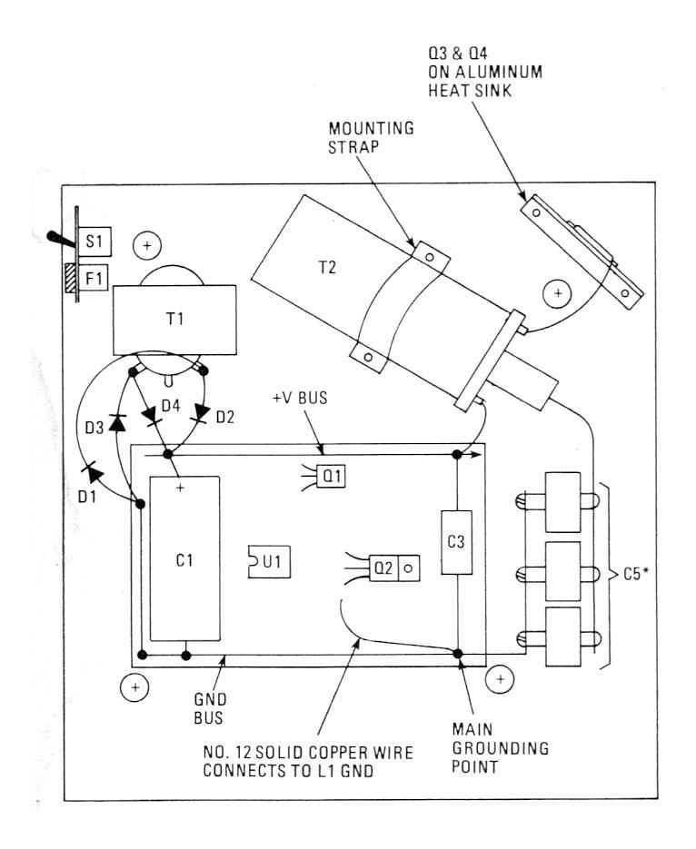
A 2 1/2-inch piece of aluminum is formed into an "L" bracket, which is used to hold S1 and F1 (see photo), and is mounted on one corner of the baseboard. A 5 X 3-inch piece of aluminum mounts to the opposite corner and functions as the heat sink for the two power transistors (Q3 and Q4). A simple band is formed from aluminum to hold T2 in place.
Recall that C5 is really three 500-uF doorknob capacitors. Two brass strips, about 3/8-inch wide by 3-inches long, are used to tie the three high-voltage capacitors together. If doorknob capacitors cannot be located (often they can be salvaged from older black-and-white TV's), a substitute can be made from window glass and aluminum foil.
To fabricate C5, take a 10-inch square piece of glass, like that of a picture frame, and glue a 9-inch square piece of aluminum foil to the center of the glass on both sides, leaving an equal border around each aluminum plate. Cut two 6-inch lengths of #22 insulated stranded wire. Strip about 3-inches of insulation from one end of each wire and tape the stripped end to each of the aluminum plates.
The Deck
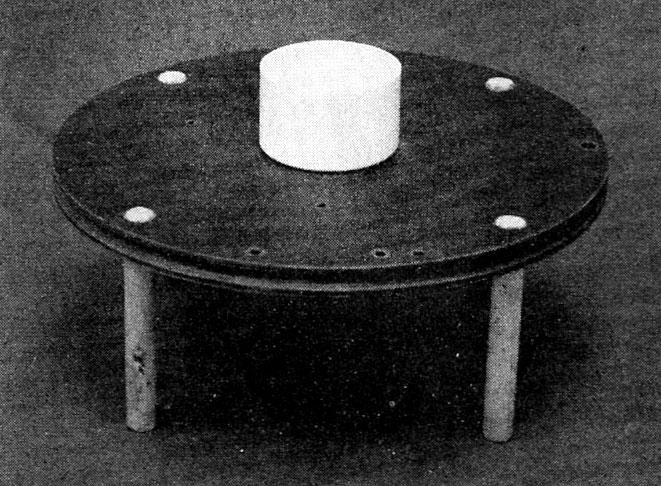
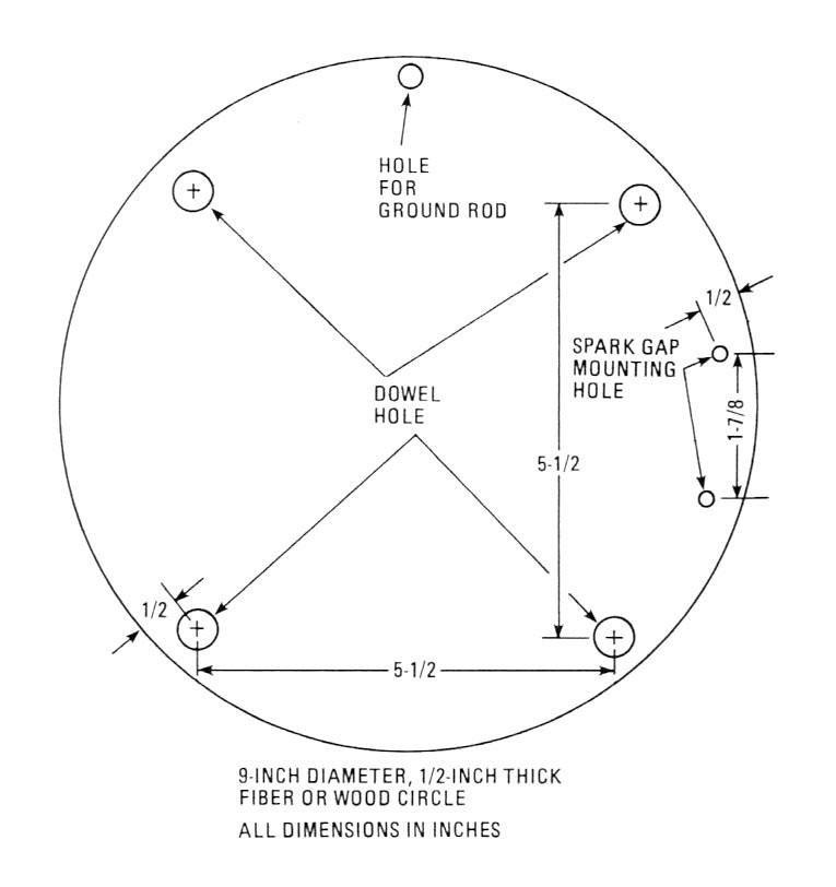
Figure 4 and the photos show the top deck of the author's prototype, where the two air-core coils (L1 and L2) are mounted. The top deck consists of a 9-inch diameter circle cut from 1/2-inch thick fiber board. Four 3 3/4-inch lengths of 3/8-inch dowel hold the 9-inch coil base above the perfboard.
Select a drill bit slightly smaller than the dowel rod's diameter and drill the four mounting holes in the 9-inch circle to match the illustration. Position the 9-inch circle on the baseboard at about the center, and mark the location of each hole. Drill each location on the baseboard with the same bit to a depth of about 1/2-inch.
If the two-layer Tesla coil seems like too much bother to duplicate, then build a single-level unit on a larger wooden base to suit your own needs. Actually, any good layout scheme that respects the dangers of high voltage should do quite well.
Winding the Primary Coil
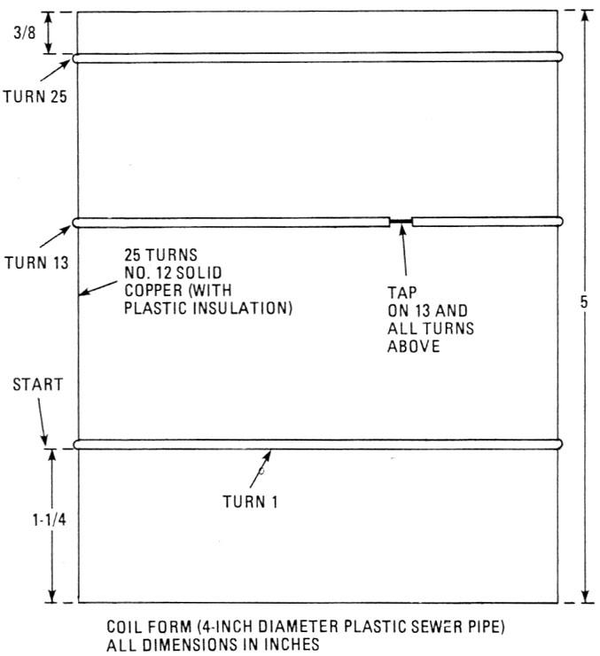
The primary-coil (L1) is wound on a form cut from a 4-inch diameter, plastic sewer pipe to a length of five inches (see Fig. 5). Take a 27-foot piece of #12 insulated solid-copper wire and strip away a 1/8-inch section of insulation at about every 12 inches, continuing for one-half the length of the wire (12 times total). Those stripped areas serve as tap points for tuning the coil.
Wind the coil starting at the top of the coil form (see Fig. 5) with the end that has the 12 tap points. In other words, turn 25 is the first winding to be made. That gives a tap on every turn from turn number 13 to turn number 25. Drill two small holes in the coil form where the winding starts and ends. Those holes are used to secure the ends of the windings (see photos).
Winding the Secondary Coil
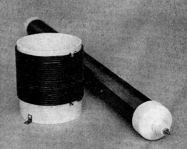
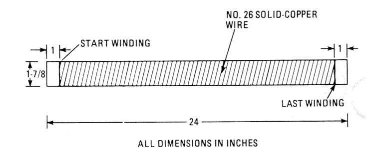
The secondary coil form (see Fig. 6) is cut from a section of 1 1/2-inch diameter, plastic water pipe (which actually measures 1 7/8-inches in diameter). So when selecting your secondary coil form, take a ruler with you and be sure to come home with the correct-diameter pipe. You'll also need two plastic end caps that snugly fit the ends of the tubing.
Make a mark on the coil form about one inch from each end. That sets the starting and ending points for the winding. Fill the space between marks with a neat solenoidal winding of #26 enamel-covered copper wire. Winding the coil by hand shouldn't take over an hour, and if a lathe is handy, you should be able to complete the job in about 15 minutes. Leave about 6-inches of wire at both ends of the winding tor making connections.
Spray several coats of Krylon clear #1301 acrylic on the coil for added insulation and protection against moisture. Always let each coat dry completely before applying the next. Two or three coats are sufficient.
It's Coming Together
Mount one of the 1 1/2-inch, plastic end caps to the center of the 9-inch circular deck with a 1-inch long #8-32 screw, washer, and nut. Take two small metal "L" brackets and mount the primary coil centered around the end cap on the 9-inch base. Drill a small hole through the end cap and baseboard near the rim of the cap. Take the secondary coil and push one end of the coil's lead through the hole in the end cap, and then set the coil in the end cap.
Take the other end cap and drill a hole in the center to clear a #8-32 screw, and mount a feed-through insulator (see photo) on top. Select a #8-32 screw long enough to stick through the top of the insulator by about ½-inch, and grind the end to a nice sharp point. Connect the top end of the secondary coil to the bottom of the #8-32 screw with a small solder lug and tighten in place. Place the cap on top of the coil.
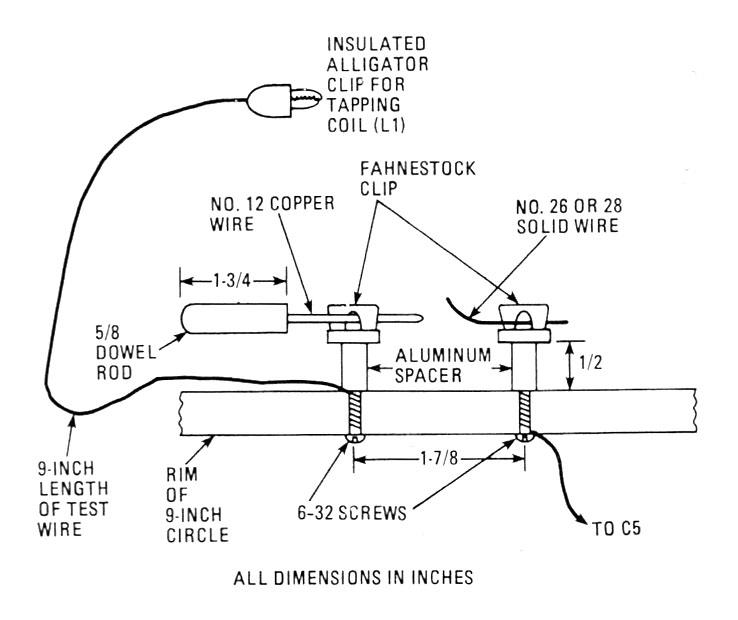
The spark gap is shown in Fig. 7. Two holes are drilled to clear a #6-32 screw to match the drawing in Fig. 4. Two fahnestock clips are mounted to the board on 1/2-inch aluminum spacers, using #6-32 hardware. A l 3/4-inch length of #12 solid-copper wire is fitted in one end of a 1 3/4-inch piece of dowel rod to produce the adjustable terminal of the spark gap. The other gap wire must be made from a #26 or smaller wire for the gap to perform properly.
Place the four dowel rods in the baseboard, position the 9-inch deck on top, and press down until all four dowel rods are even with the top of the circle. Connect the bottom of L1, using a short length of #12 wire, to the main grounding point (see Fig. 3). Also connect the bottom end of L2 to the same point.
A separate vertical ground rod can be positioned on the deck (see photos) for additional experimenting. The vertical ground was made from a 29-inch length of 1/4-inch threaded rod, and covered with a section of aluminum tubing to give a neat appearance. At the top, a binding post was mounted for versatility. That allows the ground rod to accept a number of different experimental items.
Checking It Out
Before we start this stage of construction, a word of warning is in order:
Do not touch or make any adjustments while power is applied to the Solid-State Tesla Coil. Remember that you'll be dealing with high voltages, so caution is the watchword.
With the power off, set the spark gap for a 1/8-inch gap and connect the tap clip to turn 15 or 16. Plug in the power cord and turn S1 on. A loud electrical discharge should be heard, and a blue brush discharge should be seen at the top of the pointed screw that's connected to L2.
Turn the power off and move the tap wire (that's connected to L1) up or down one turn at a time until the greatest blue discharge is obtained at the top of L2. Form a 1 1/2 to a 2-inch vertical gap between the ground rod and the top of the coil to aid in tuning up the coil. When the Tesla coil is properly adjusted, it should produce a 2-inch arc between the top of L2 and the ground terminal.
The coil discharge is most dramatic in a darkened room, and you should be able to light a fluorescent lamp at a distance of about two feet from the secondary coil. A clear incandescent lamp moved to within a few inches of the secondary coil will produce a beautiful blue lightning array from the lamp's filament to the outer edge of the glass envelope. Neon lamps glow around the coil without wires. Experimenting with the coil can be an almost endless adventure. But remember, always put safety first!