Plans
Neon Sign Transformers for the Researcher
Richard Hull
7103 Hermitage Rd.
Richmond, VA 23228
E-mail:
[email protected]
The neon sign transformer is investigated to examine just what the nameplate rating means and how the researcher might intelligently select and use these low cost sources of high voltage in their laboratory work.
This paper is the result of a friendly dispute between Scott Fusare, a fellow researcher, and me that occurred while visiting the ESI research facility in late December of 2002. Scott contended that the neon sign transformer pretty much supplied its nameplate rated voltage and current. I noted that in my experience as a Tesla coil builder in the 90s, the transformer’s magnetic shunting would never allow the transformer to satisfy its ratings before reducing the magnetic flux to a point where the voltage would precipitously drop while supplying nowhere near the nameplate rated current.
We both were fully aware that the neon sign transformer is magnetically shunted. In this manner a high voltage can be applied to cold gas at reduced pressure, as in signage, causing the gas to ionize and glow. Once ionized, the internal resistance of the gas plummets and tremendous currents are demanded. In attempting to do this, the magnetic flux within the transformer core is shunted away from the windings causing a tremendous voltage reduction. The current rises only slightly and voltage is now reduced to a safe level needed to keep the hot gas ionized. This remains a rather ingenious, low cost, yet simple piece of magnetic engineering, even to this day.
Tesla coil builders have used this relatively safe and inexpensive form of high-voltage transformer for years in making smaller Tesla coil systems. Other experimenters and researchers have also availed themselves of this device mostly due to its attractive cost and reduced size coupled with its modest demands on input power.
The point of contention between Scott and me lay in the point at which the designers of the devices “turned on” the shunting. I turned to a simple experiment as the final arbiter of the truth in this matter.
Setup
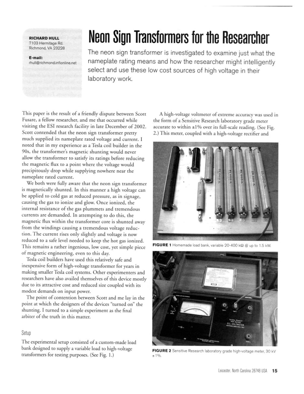
The experimental setup consisted of a custom-made load bank designed to supply a variable load to high-voltage transformers for testing purposes. (See Fig. 1.)
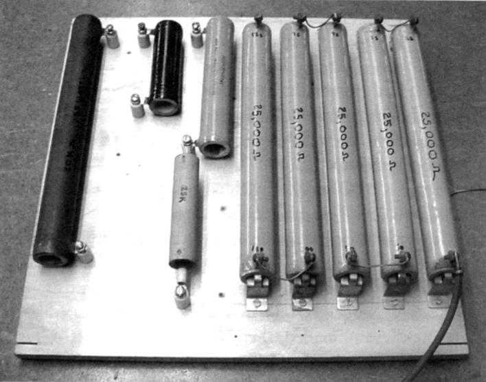
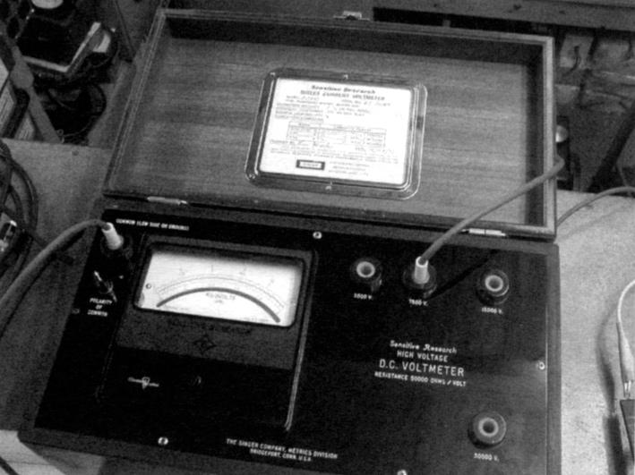
A high-voltage voltmeter of extreme accuracy was used in the form of a Sensitive Research laboratory grade meter accurate to within ±1% over its full-scale reading. (See Fig. 2.) This meter, coupled with a high-voltage rectifier and filter capacitor, allowed recording of the “peak” AC voltage output of the transformer under test. Naturally, this was converted to rms voltages for graphing purposes. (Root mean square or rms voltages are those normally used in the AC power business and those read by practically all meters connected to smoothly varying sinusoidal power sources. The rms value is given by the simple equation VACrms = .7071 x VACpeak.) An AC variac or variable transformer was used to vary the input voltage to the primary of the transformer under test. A digital voltmeter was used to record the applied AC rms voltage to the primary of the transformer under test. Such meters are accurate in this application, as the voltage measured is a smooth sinusoidal voltage. In experiments involving sparks, pulses, or irregularly varying AC waveforms, they are worthless. They are used in all sorts of “new energy tests” where they are less than worthless. In such situations they are deceptive and indicative of the rankest of amateur efforts.
Procedure
The load on the transformer could be varied over a wide range, but the ideal test load was arrived at by looking at the nameplate of the transformer and calculating the rated resistive load impedance of the device. Thus, the 5 kV, 30 mA nameplate, by Ohm’s law, yielded a source impedance of 5000 V/0.030 A, so 166,666 Ω was used as the rated load in the test with that particular transformer. The 7.5 kV, 120 mA transformer required a 7500 V/0.120 A or 62,500 Ω load. I used a 62 kΩ load in this test.
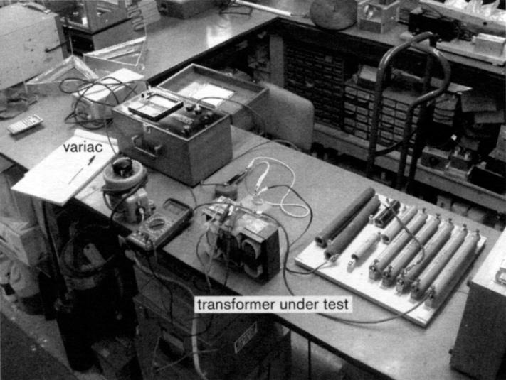
Data was collected on the two transformers tested by first leaving them unloaded, then increasing the input voltage in 10 V steps up to the 120 V line voltage and recording the corresponding high-voltage output of the transformer secondary. Once this was done, various loads were applied across the secondary and the process repeated to see how loading affected the output voltage. (The entire experimental setup is shown in Fig. 3.)
Data
Graphs were made of the various load lines associated with the two transformers tested for this paper. It was decided to focus on the 30 mA transformer in varying load tests, as this is the type most often encountered by the amateur in search of used or surplus neon sign transformers. For my personal edification a “monster” high current, 120 mA neon-type transformer was tested as well to see if it fared any better than the standard 30 mA units.
The data was recorded in peak kV and converted to rms values prior to placing it into the spreadsheet format used to generate the graphs. Readings and calculations were rounded off to the second decimal place. Great care was taken in reading and interpolating the analog meter movement readings. This is an area that often befuddles many amateurs not used to interpreting scales of varying graduation factors.
Figure 4 shows the results of various tests run on the 5 kV 30 mA sign transformer. It can be seen that at no load, the transformer is capable of outputting its nameplate rating of 5 kV rms. Unfortunately, at rated load output (the 166 kΩ load line) the output is far below the rated value, being no more than 3.2 kV and supplying no more than 19.5 mA. This indicates that at full nameplate load the transformer can supply about two-thirds of the rated current and two-thirds of the rated voltage.
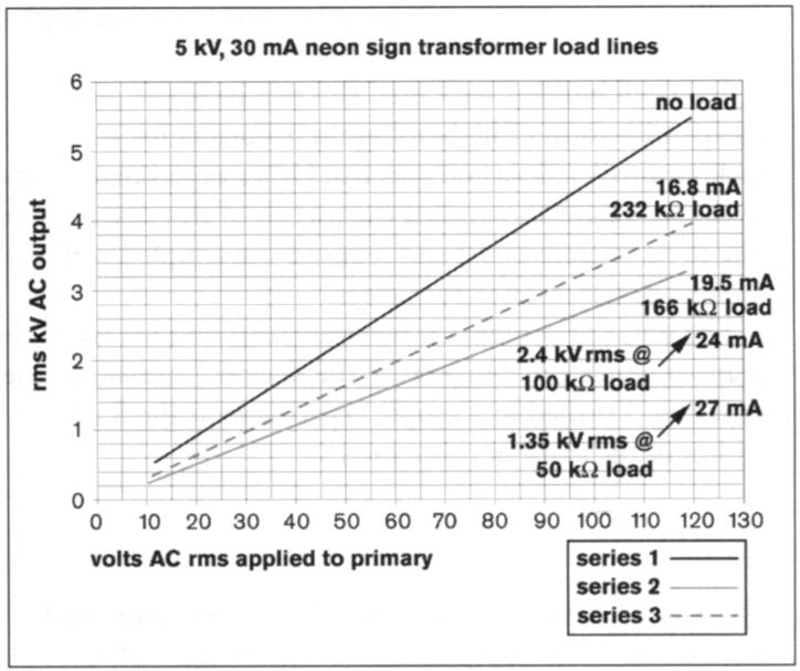
At a lighter loading of 232 kΩ, the voltage was up to nearly 4 kV, while the current dropped to 16.8 mA. At higher than rated loadings the voltage really dropped. It can be seen that the voltage was only 2.4 kV when the current was 24 mA and that only 1.35 kV was available at 27 mA. Thus, only at ultra-light loadings can the nameplate voltage even be approached. Likewise, full rated current can only be had at nearly one-fifth of the rated potential of the transformer.
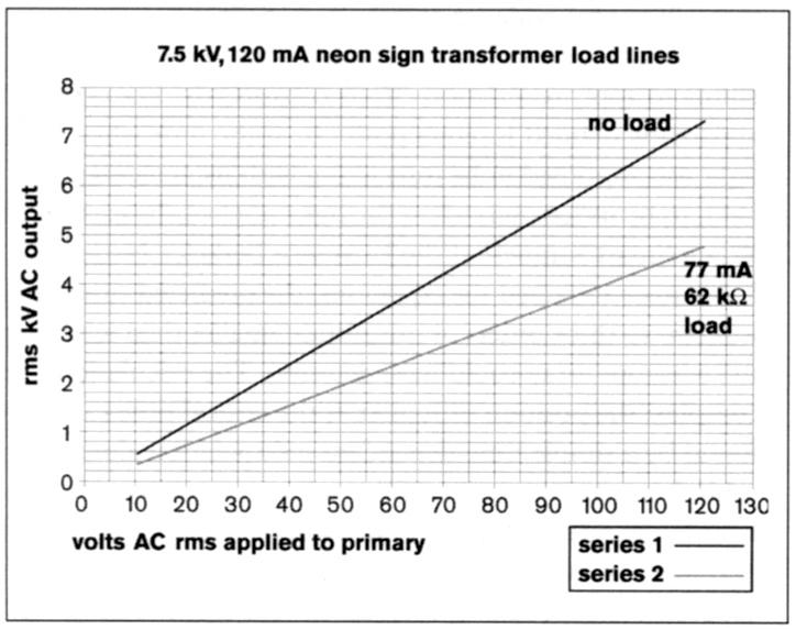
Figure 5 is the result of testing a much more “beefy” neon sign transformer. It can be seen that the line for rated load mimics the lower power transformer tested above.
Conclusions
It appears most sign transformers can be viewed in light of a two-thirds rule. No more than two-thirds of the rated voltage or current may be had, concurrently, at the rated nameplate loading. Furthermore, full voltage can only be obtained at zero loading. Extremely light loading can result in nearly full voltage output, but even moderately light loading can result in a rather severe drop in output voltage. As regards current, the full rated current can only be had at the expense of voltage; leaving as little as one-fifth of the nameplate voltage rating remaining at the rated current.
The above proves my point to Scott. The neon sign transformer must be chosen with care and consideration of its rather nasty characteristic of not being able to perform up to its nameplate ratings of current and voltage concurrently in any situation where continuous power is needed.
Further Thoughts on the Application of Neon Transformers
There are two configurations of neon transformers. The configurations differ in how the ground connection is made to the secondary winding. All neon secondary windings are ground referenced. That is, their secondary winding is attached at some point to the metal case and iron core of the transformer. This is designed to be a connection to electrical power ground. As such, a large bolt is always found on the case for this connection.
Small transformers of 5 kV and below usually have one end of their single secondary winding attached to the case and core that must be grounded. All larger, higher-voltage transformers have two secondary windings hooked in series, and the central tie point of the two is always grounded to the case and core. The outer two ends then go to the high-voltage insulators. This allows for the use of less insulation in the secondary windings, thereby reducing cost and physical size.
The above grounding methods impose further limits on transformer applications if rectification is required for use in DC supplies that must be ground referenced, usually at the negative polarity. A 15,000 V neon transformer can’t be bridge rectified to produce a 15,000 x 1.414 = 21.2 kV DC supply, with the positive or negative lead grounded, and still allow the case to be grounded. If the case ground is lifted to allow this large voltage rectification, two very dangerous situations exist. First, the case would be at 7,500 V hot potential and could be lethal to anyone touching it. Secondly, the insulation of the primary wound on the hot core may fail, creating a power arc and subsequent fire hazard.
With proper grounding assured, via good practice, the 15,000 V transformer can only be full-wave rectified to no more than 7,500 x 1.414 = 10,600 V DC with proper filtering.
While these transformers are low priced, self-limiting and well-grounded by design, it is these very same features that severely limit their application as general purpose, continuous output, power transformers. The experimenter who is well-informed and careful to design with these limitations in mind will be successful.
Postscript
It is in the nature of experimenters to question, argue and be contentious; especially, among themselves. This paper settling the question regarding the difference of opinion between Scott and me was done the right way, the way suggested by Benjamin Franklin over two centuries ago, “Let the experiment be done.” It is not at all important who is right or wrong, for each of us has his turn eating crow. The final result will always be the truth as illuminated by empirical experiment and knowledge given to all parties privy to the results.