Plans
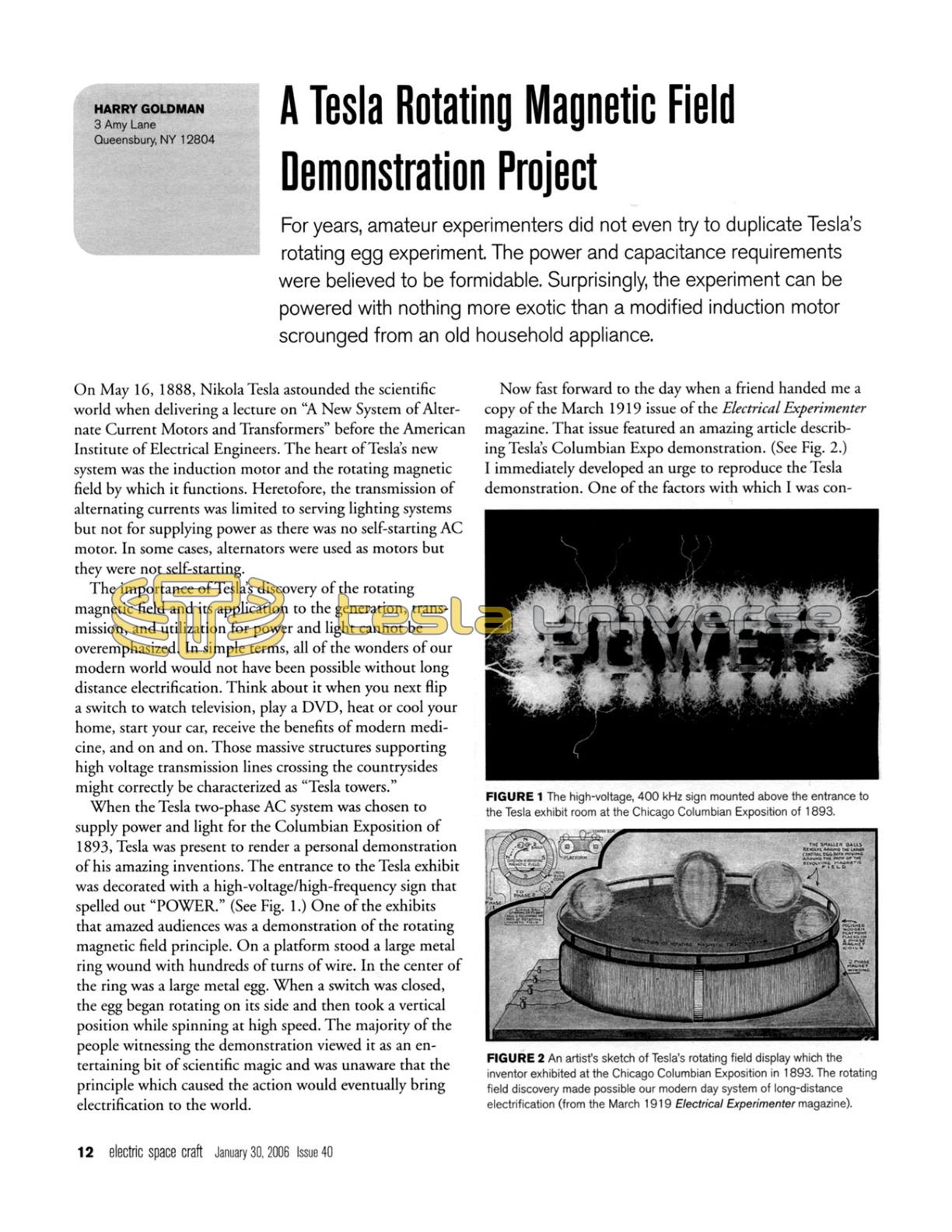
A Tesla Rotating Magnetic Field Demonstration Project
For years, amateur experimenters did not even try to duplicate Tesla's rotating egg experiment. The power and capacitance requirements were believed to be formidable. Surprisingly, the experiment can be powered with nothing more exotic than a modified induction motor scrounged from an old household appliance.
On May 16, 1888, Nikola Tesla astounded the scientific world when delivering a lecture on "A New System of Alternate Current Motors and Transformers" before the American Institute of Electrical Engineers. The heart of Tesla's new system was the induction motor and the rotating magnetic field by which it functions. Heretofore, the transmission of alternating currents was limited to serving lighting systems but not for supplying power as there was no self-starting AC motor. In some cases, alternators were used as motors but they were not self-starting.

The importance of Tesla's discovery of the rotating magnetic field and its application to the generation, transmission, and utilization for power and light cannot be overemphasized. In simple terms, all of the wonders of our modern world would not have been possible without long distance electrification. Think about it when you next flip a switch to watch television, play a DVD, heat or cool your home, start your car, receive the benefits of modern medicine, and on and on. Those massive structures supporting high voltage transmission lines crossing the countrysides might correctly be characterized as "Tesla towers."
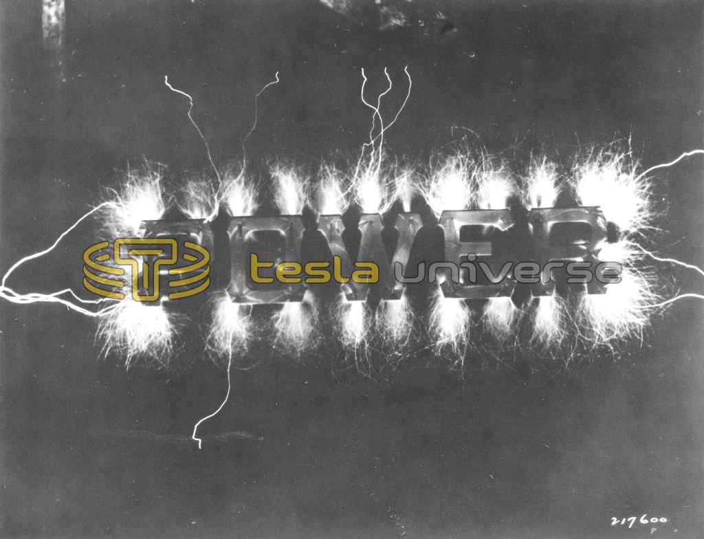
When the Tesla two-phase AC system was chosen to supply power and light for the Columbian Exposition of 1893, Tesla was present to render a personal demonstration of his amazing inventions. The entrance to the Tesla exhibit was decorated with a high-voltage/high-frequency sign that spelled out "POWER." (See Fig. 1.) One of the exhibits that amazed audiences was a demonstration of the rotating magnetic field principle. On a platform stood a large metal ring wound with hundreds of turns of wire. In the center of the ring was a large metal egg. When a switch was closed, the egg began rotating on its side and then took a vertical position while spinning at high speed. The majority of the people witnessing the demonstration viewed it as an entertaining bit of scientific magic and was unaware that the principle which caused the action would eventually bring electrification to the world.
Now fast forward to the day when a friend handed me a copy of the March 1919 issue of the Electrical Experimenter magazine. That issue featured an amazing article describing Tesla's Columbian Expo demonstration. (See Fig. 2.)
I immediately developed an urge to reproduce the Tesla demonstration. One of the factors with which I was concerned was the huge amount of power required to create the spinning effect. It was stated that Tesla ran it on as much as 200 horsepower! Secondly, an electrical engineer friend with whom I had discussed my intentions calmly informed me that my project would demand a "huge" capacitor. Although my confidence in achieving success began to dwindle, the idea of constructing a spinning egg demo remained in my thoughts throughout the years.
As time passed, I kept attentive to the popular science magazines hoping that writers such as the brilliant Harold Strand would bring forth a simple Tesla spinning egg project. I also searched papers pertaining to science fair literature with the thought that a junior scientist would undertake such a project. It wasn't until I came across a book written for junior-senior high school students that I found my answer. The project, I discovered, could be made to function on less than one-tenth horsepower. And as to that required "huge" capacitor, it turned out to be much smaller than I had envisioned.
Basically, the common induction motor consists of four fixed (field) coils of many turns of wire. This section is called the stator. Another coil of fewer turns is centrally mounted and free to turn. This section is referred to as the rotor. Unless you choose to wind your own field coils, you will have to obtain an induction motor to complete this project.
Induction motors are so prevalent in our society that the experimenter should have little difficulty in obtaining one. Local businesses in the home appliance trade are good sources. I have obtained several at little cost from a store that had a number of old refrigerators and washing machines that were ready to be junked. As an aside, when I was enthusiastically constructing Tesla coils, our nearby heating and cooling establishments became a good source for used ignition transformers. Some charged as little as one dollar while others allowed me to retrieve the transformers from discarded oil furnaces at no cost. I later was able to pick up some decent spending money by providing local night clubs with used ignition transformers for their weird neon light displays. Hooray for a free market economy.
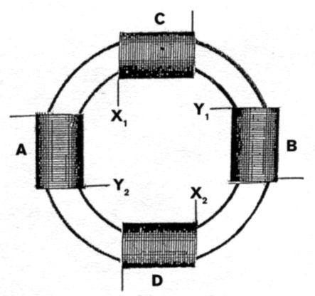
The first step in preparing the motor for a two-phase arrangement is to remove both end plates and pull out the rotor. Next, disconnect the four stator coils so that you end up with two leads coming from each one. (See Fig. 3.) This is the trickiest part of the project. Take the leads coming from the four coils and connect them so that they become two separate sets of coils hooked in series. One set of two coils is labeled A & B, while the other set becomes C & D. Notice that coil A is opposite coil B, and that coil C is opposite coil D. (See Fig. 4.)
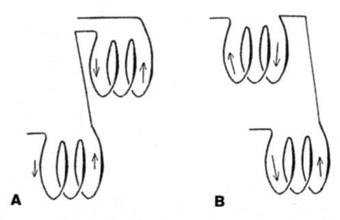
The coils should be connected in such a way that the turns of wire making up the second coil in each set continue in the same direction as the first (both clockwise or both counterclockwise). Coils with turns in the same direction are said to be aiding. (See Fig. 5a). If one coil is wound clockwise and connected to the other in a counterclockwise direction, the coils are said to be in a bucking or canceling configuration. (See Fig. 5b.)
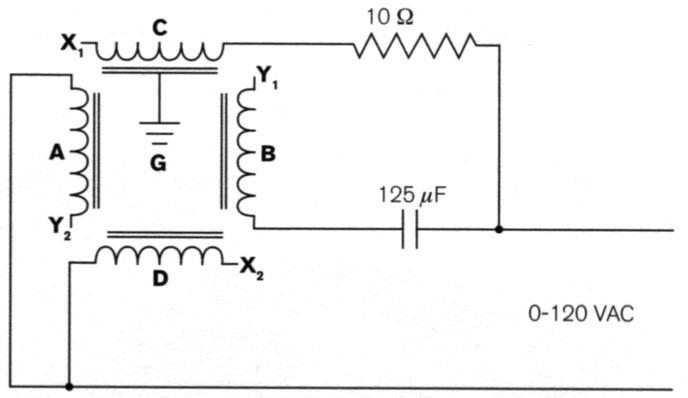
Figure 4 mentions two methods for achieving two-phase AC. The wiring in each is identical. The only difference is whether a capacitor or inductive resistance or choke is selected. When a capacitor is used in circuit A-B, the current will lag. In this arrangement, circuit C-D will peak first. In my experiments, the capacitor circuit rotated objects in a counterclockwise direction. The opposite effect occurred when the reactance was installed. I chose to use the capacitor only because of its lighter weight. (See Fig. 6.)
The objective is to get circuit A-B to be 90 electrical degrees out-of-phase with circuit C-D. If you select an induction motor similar in horsepower to my apparatus (1/6 hp), the values given in the schematic will be good ballpark measurements with which to start.
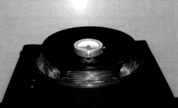
An oscilloscope is a valuable test instrument for determining proper phasing. When both circuits are 90 electrical degrees apart, the Lissajous pattern will be a circle. The good news is that an oscilloscope is not absolutely necessary for phase testing. An inexpensive magnetic compass will work nicely. Place the compass on a nonmetallic (plastic, wood, glass, ceramic, etc.) surface, and position it on top of the field coils. (See Fig. 7.) WARNING! DO NOT CONNECT YOUR PROJECT DIRECTLY TO A 120 V LINE. Only a few volts are necessary to indicate proper phasing. If the compass needle favors one set of coils more than the other, then proper phasing has not been achieved. Raising the voltage will have no effect on phasing.
It is strongly recommended that phasing tests be carried out with a low-voltage source. A variable voltage transformer (variac, Powerstat, etc.) will be useful not only for phasing but also for powering up the completed project. It is preferable to apply a variable transformer equipped with both voltage and amperage indicators. This will allow complete control over what is happening.
The amount of power required to achieve rotation will vary according to an object's mass. Hollow metal components demand less energy than those of solid metal. And after the object is rotating, it takes less power to keep it spinning (as we were told in high school physics). While I was carrying out some experiments, a spinning component would occasionally be hurled across the room because of my failure to reduce the power level. (I must have skipped school the day the instructor discussed inertia, centrifugal force, etc.)
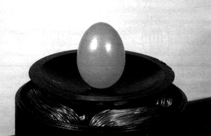
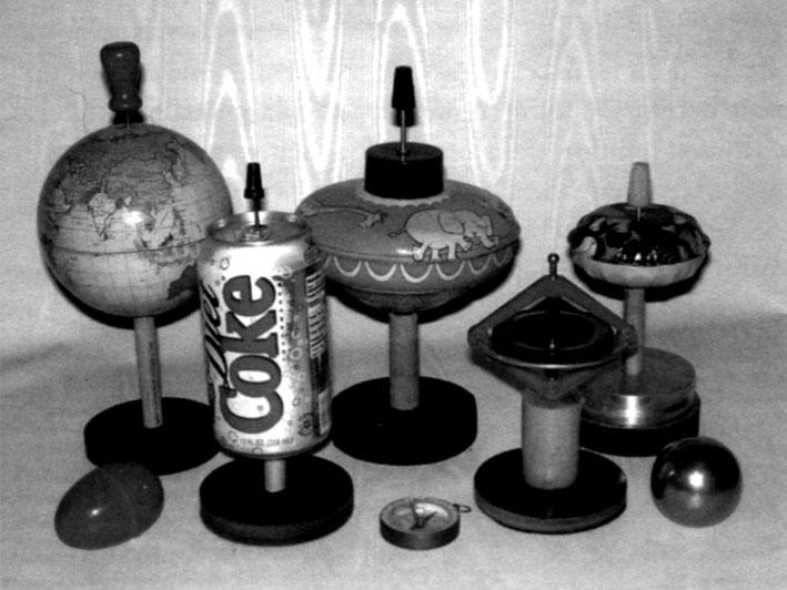
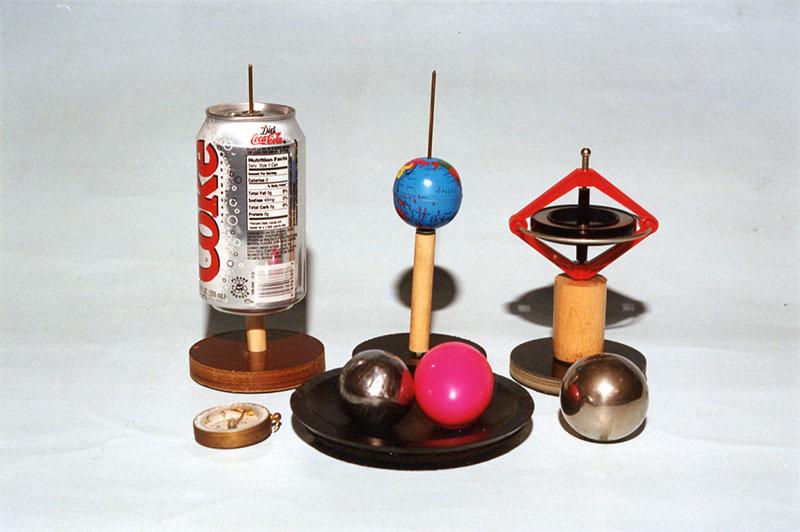
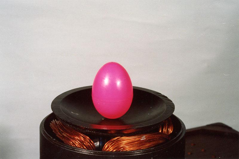
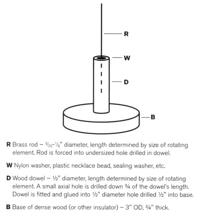
Nonferromagnetic materials such as aluminum, copper, and brass are preferred. It is also possible to rotate spheres, discs, eggs, etc. made up of ferrous metals. With a bit of ingenuity, nonmetal objects can be made to spin (if there is some metal inside). A plastic Easter egg packed with steel wool can be made to stand on end and spin as fast as a whirling top. (See Fig. 8.) In fact, I have produced rotation with a children's toy top, Coca Cola can, gyroscope, and other items of various shapes. (See Fig. 9.) These required a simple stand to keep them in the proper position to allow rotation. (See Fig. 10.)
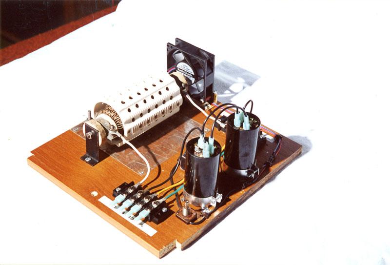
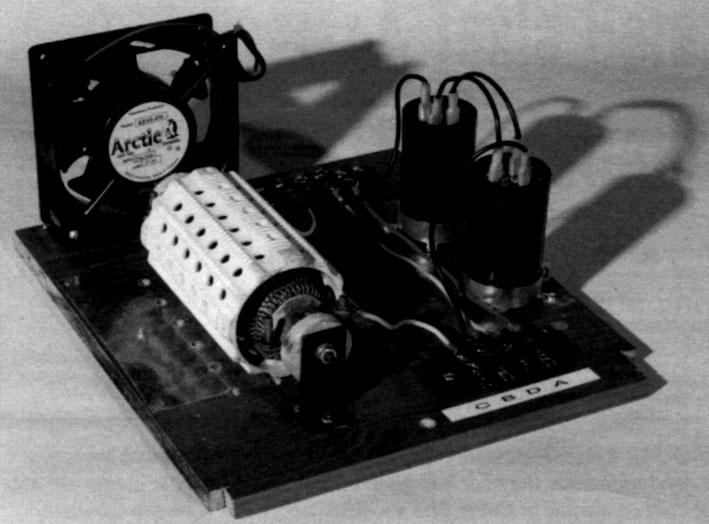
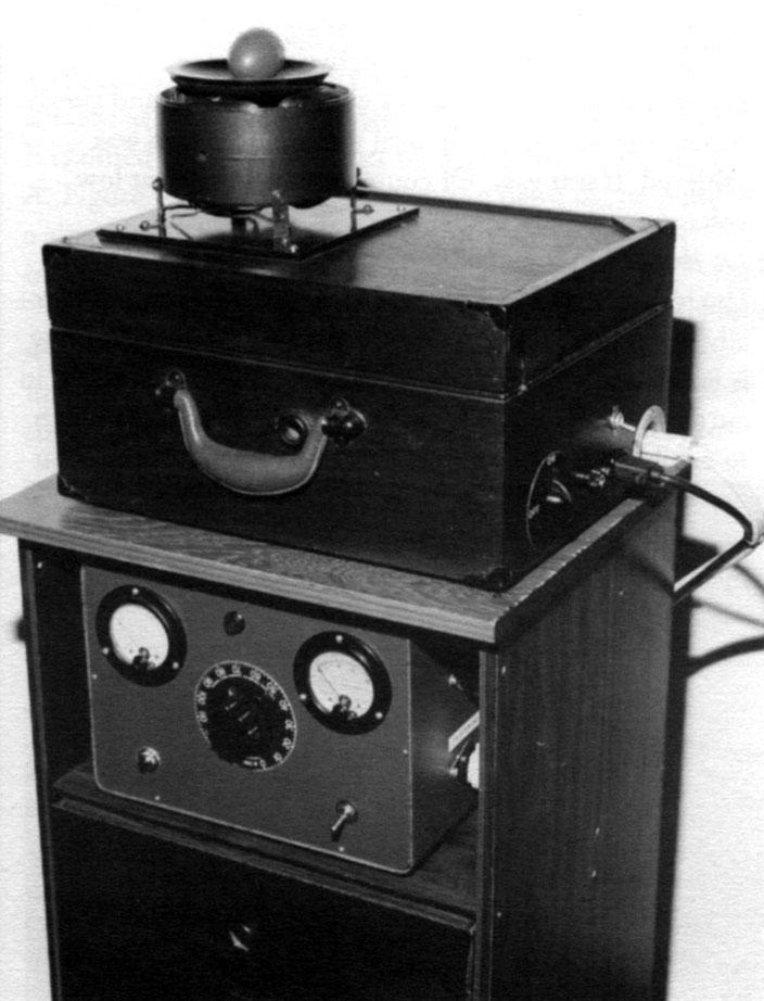
But there is a fly in the ointment. The major challenge to this project is finding a suitable high-power resistor. As much as 1800 VA may be in demand when running the circuit at maximum voltage. Finding a resistor to handle that kind of power can be difficult (and expensive). The component providing the resistance in my project is an element from a heater. As expected, it does produce a significant amount of heat when the unit is drawing more than 10 A. A fan was installed to remove the heated air from within the case. A low wattage resistor of, say, 500 W will work if the circuit is operated at reduced power. Of course, arranging resistances in series-parallel connection is another option. Figure 11 represents the complete project.
Demonstrating this project before fellow experimenters and technically informed citizens brought forth a mix of inquiries. The following represent a few of the questions with my responses.
Q: Can a project such as yours be made on a smaller scale?
A: Yes. The reference I used described a small project powered by 12 VAC.
Q: If I wanted to build a project on a reduced scale, how many turns will be required for each field coil, and what value of resistance should be used?
A: Three hundred turns should do. The resistance can be about 10 Ω.
Q: Induction motors have a low starting torque and must have a starter coil to get them up and running. Did you leave the starter coil in place?
A: No. Only the field coils were retained.
Q: What factor influenced the choice of resistance you used?
A: I started with 10 Ω and did not investigate the effect of higher resistances which I should have done. Once I got the project running, I never went back.
Q: What kind of capacitor is best for a project such as yours?
A: Use capacitors marked expressly for alternating current motors. These have AC ratings only. Avoid capacitors marked for direct current or having DC ratings.
Q: Why go to all the trouble of disconnecting the field coils and reconnecting them in series? Wouldn't it be easier to just remove the rotor and plug it in?
A: This would draw a heavy current and throw open your circuit breakers. I don't know if this could produce the desired results, even if you run it on low power. If you intend to attempt rotating field experiments with this arrangement, do so at very low voltage.
Q: How did you go about finding the capacitance and inductance values?
A: I applied the compass test for determining correct phasing. With the capacitor, it was strictly trial and error. The original plan for a small two-phase project suggested a capacitance of 30 uF. I doubled it and continued adding capacitance until the compass needle began to rotate. As for finding the correct inductive reactance, I merely placed a small variac in series with circuit A-B and slowly turned the control knob until two-phase action was achieved. It was easy. Of course, this was done at low voltage.
Q: Do the field coils get hot during the demonstrations?
A: The resistor will overheat before the field coils do. Generally, operation can be continuous when the current draw is 8 A or less. Display time diminishes with an increase in current. At 15 A, I only operate the project long enough to exhibit the rotating field principle. Keep in mind that power levels can be significantly reduced once a component is set in motion. This increases the amount of display time for any particular rotating component.
Comments are welcome, especially from anyone with experience with this phenomenon.
References
- Crow, Leonard R. 1951. Learning electricity and electronics experimentally. Vincennes, Indiana: The Scientific Book Co., pp. 147-161.
- Meiners, Harry F. 1970. Physics demonstration experiments. Vol. 2. New York, NY: The Ronald Press Co., pp. 943-946.
- Pearce, W. E., 1962. School experiments with alternating current. London: G. Bell & Sons., pp. 114-116.
Errata
Harry Goldman called attention to a misprint in his article, "A Tesla Rotating Magnetic Field Demonstration Project," ESJ 40. The first paragraph on page 14 read, "...When a capacitor is used in circuit A-B, the current will lag. In this arrangement, circuit C-D will peak first."
For a capacitor, the maximum current will appear to lead, while the voltage must slowly build or lag, reaching a maximum 90° out-of-phase. For an inductor, the maximum voltage will appear instantly across the coil, while the current slowly builds, reaching a maximum 90° out-of-phase. The current and voltage in complex inductive circuits will be a combination of these effects that depends on the capacitance and inductance of the components.
The editors of ESJ apologize to Mr. Goldman and our readers for this error on our part.
Additional photos provided by author