Plans
Tesla Turbine - Part 1
Photos and drawings by Author
Nikola Tesla is best remembered as the inventor of the AC induction motor and the three-phase system of AC power generation and distribution that is universally used today. Tesla is also remembered for his experiments with high voltage and RF (radio frequency) apparatus; most people know what a Tesla coil is. Tesla also worked a lot with, and received many patents for, mechanical apparatus. One of these devices is the Tesla turbine. This machine has intrigued me ever since I first read about it, and I’ve wanted to build one for a long time. I was able to find material in biographies of Tesla that mentioned the turbine, and was able to get a general description of it, but found no solid details of how a true Tesla turbine should be built.
All conventional turbines have some sort of arrangement of blades. The Tesla turbine is unique in that it has no blades at all and works on different principles. Conventional turbines operate on a combination of expansion through sets of stationary and moving blades and impulse on the blades. Some turbines are pure impulse (like my Terry Turbine published in Live Steam magazine).
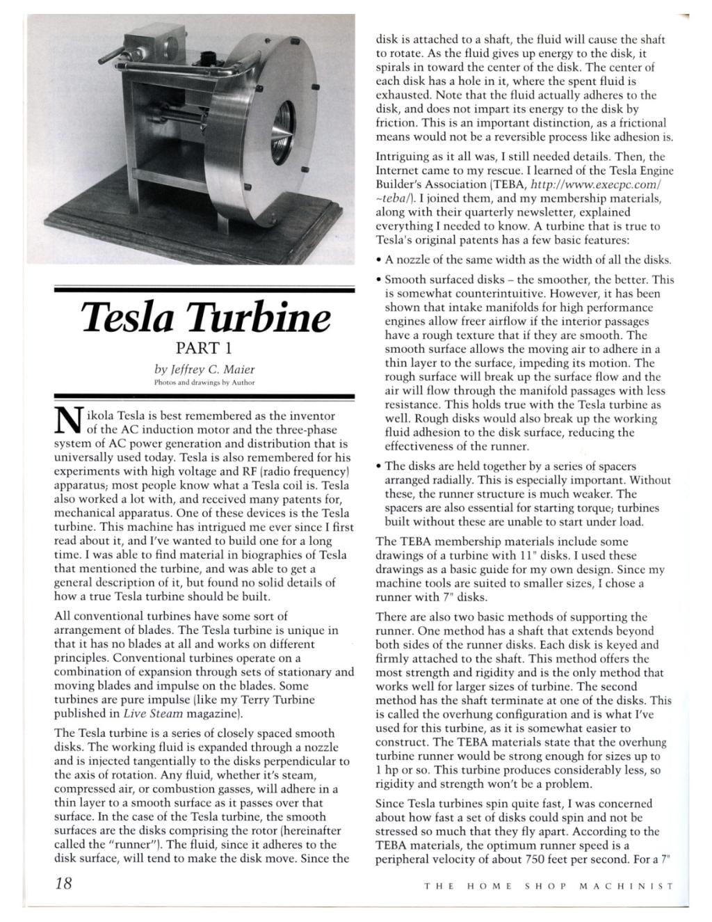
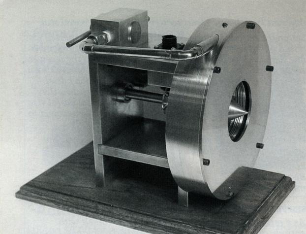
The Tesla turbine is a series of closely spaced smooth disks. The working fluid is expanded through a nozzle and is injected tangentially to the disks perpendicular to the axis of rotation. Any fluid, whether it’s steam, compressed air, or combustion gasses, will adhere in a thin layer to a smooth surface as it passes over that surface. In the case of the Tesla turbine, the smooth surfaces are the disks comprising the rotor (hereinafter called the “runner”). The fluid, since it adheres to the disk surface, will tend to make the disk move. Since the disk is attached to a shaft, the fluid will cause the shaft to rotate. As the fluid gives up energy to the disk, it spirals in toward the center of the disk. The center of each disk has a hole in it, where the spent fluid is exhausted. Note that the fluid actually adheres to the disk, and does not impart its energy to the disk by friction. This is an important distinction, as a frictional means would not be a reversible process like adhesion is.
Intriguing as it all was, I still needed details. Then, the Internet came to my rescue. I learned of the Tesla Engine Builder’s Association (TEBA, http://www.execpc.com/~teba/). I joined them, and my membership materials, along with their quarterly newsletter, explained everything I needed to know. A turbine that is true to Tesla’s original patents has a few basic features:
- A nozzle of the same width as the width of all the disks.
- Smooth surfaced disks - the smoother, the better. This is somewhat counterintuitive. However, it has been shown that intake manifolds for high performance engines allow freer airflow if the interior passages have a rough texture that if they are smooth. The smooth surface allows the moving air to adhere in a thin layer to the surface, impeding its motion. The rough surface will break up the surface flow and the air will flow through the manifold passages with less resistance. This holds true with the Tesla turbine as well. Rough disks would also break up the working fluid adhesion to the disk surface, reducing the effectiveness of the runner.
- The disks are held together by a series of spacers arranged radially. This is especially important. Without these, the runner structure is much weaker. The spacers are also essential for starting torque,- turbines built without these are unable to start under load.
The TEBA membership materials include some drawings of a turbine with 11” disks. I used these drawings as a basic guide for my own design. Since my machine tools are suited to smaller sizes, I chose a runner with 7” disks.
There are also two basic methods of supporting the runner. One method has a shaft that extends beyond both sides of the runner disks. Each disk is keyed and firmly attached to the shaft. This method offers the most strength and rigidity and is the only method that works well for larger sizes of turbine. The second method has the shaft terminate at one of the disks. This is called the overhung configuration and is what I’ve used for this turbine, as it is somewhat easier to construct. The TEBA materials state that the overhung turbine runner would be strong enough for sizes up to 1 hp or so. This turbine produces considerably less, so rigidity and strength won’t be a problem.
Since Tesla turbines spin quite fast, I was concerned about how fast a set of disks could spin and not be stressed so much that they fly apart. According to the TEBA materials, the optimum runner speed is a peripheral velocity of about 750 feet per second. For a 7” runner, this translates to 24,500 rpm. In Machinery’s Handbook, 23rd edition, page 196, a formula describes the stress in a rotating disk with a hole in the center - exactly what we have with a Tesla turbine runner. The formula is as follows:
St = 7.1 x 10⁻⁶wN2[(3+m)R2 + (1-m)r2]
Where:
St = the stress in the disk, in psi.
w = the density of the disk material, in lb. per in3.
N = the speed of the disk, in rpm.
m = Poisson’s ratio of the disk material.
R = the radius of the disk.
r = the radius of the central hole in the disk.
I calculated the stresses for two materials - 304 stainless steel and 6061-T6 aluminum. The properties are as follows:
304 stainless
Tensile strength = 125,000 psi; set this equal to St above to find the maximum speed
Poisson’s ratio m = 0.291
Density w = 0.283 lb/in3.
6061-T6 aluminum
Tensile strength = 38,000 psi; set this equal to St above to find the maximum speed
Poisson’s ratio m = 0.334
Density w = 0.101 lb/in3
Outer disk radius R = 3.500”
Central hole radius r = 1.375”
Plugging these values into the formula and solving for N yields:
For 304 stainless, maximum speed is N = 38,645 rpm.
For 6061-T6 aluminum, maximum speed is N = 35,478 rpm.
Not much difference between the two materials. I had originally planned to use 304 stainless because of its greater tensile strength. However, the lower density of aluminum offsets its lower tensile strength. Since it is a lot easier to work and won’t have to withstand high temperatures, I used aluminum.
So what is the stress at our intended operating speed of 24,500 rpm? Plugging this speed into the formula and solving for St yields:
For 6061-T6 aluminum. St = 18,122 psi, or 48% of the maximum 38,000 psi.
For 304 stainless. St = 50,240 psi, or 40% of the maximum 125,000 psi.
So, it appears that the optimum operating speed will indeed be safe with the materials used. What did the actual turbine, as built, achieve? The maximum speed I obtained, unloaded, was 12,000 rpm. Under loads, I would typically get 8,000 to 9,000 rpm. The stress in aluminum disks at 12,000 rpm is 4,347 psi, or 11 % of the maximum 38,000 psi. I suspect my nozzle design is to blame for the lower than ideal speed; the velocity of the fluid escaping from the nozzle determines the runner speed.
What about power output? Issue No. 16 of the TEBA news contains an analysis of a Tesla turbine disk, including formulas to predict the torque produced by a single disk. I measured the output of my own turbine with a somewhat crude Prony brake and got the following results:
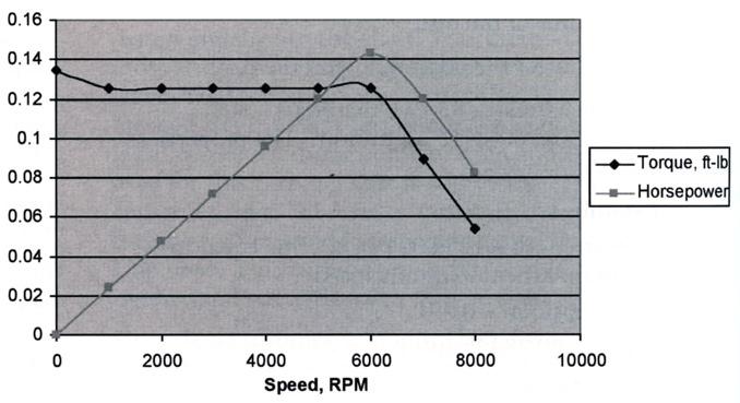
Note that the torque drops off after 6,000 rpm, after being almost perfectly flat. I had a lot of trouble getting a good measurement at higher speeds, so I don’t know if the drop-off is real or is an artifact of my admittedly crude measurement technique. In any event, how does this compare with the theoretical performance? The formula from TEBA news issue No. 16 is:
Where:
T = torque in N-m (Newton-meters)
T = 1.79 x 10⁻⁵ Ns/m2
V = the peripheral velocity of the disk in m/s.
R = the radius of the disk in m.
r = the radius of the central hole in the disk in m.
h = one half the disk spacing in m.
This gives the torque produced by one side of one disk. This turbine has a total of five disks, giving eight power-producing sides. The outside of each end disk does not produce any power. So, the theoretical torque will be eight times what the above formula predicts.
For this turbine, at 6,000 rpm (max torque from my measurements):
V = 56 m/s
R = 0.089 m
r = 0.035 m
h = 3.97 x 10⁻⁴ m
Plugging these values in gives a torque of 0.0142 N-m for one side of one disk; total torque would then be eight times this, or 0.114 N-m. This works out to 0.084 ft/lb. at 6,000 rpm, giving us 0.096 hp. Note that I got 0.14 hp at 6,000 rpm, exceeding the theoretical output. This output seems pretty small, until you note that the power output is proportional to the square of the disk diameter. A turbine with a 36” diameter disk would theoretically produce about 9 hp per disk.
Conventions
I follow certain conventions when referring to milling machine cutting directions. First, all directions are from the point of view of a person standing in front of the milling machine. The X-axis is the long axis of the table, which moves left and right. The Y-axis is the shorter axis of the table, which moves in and out. In is toward the rear of the milling machine, and out is toward the operator.
Bill of Materials
The following bill of materials provides a list of all the parts that must be machined. The overall size column is the size of a blank piece of material needed to make the part.
| QUANTITY | PART | MATERIAL OVERALL SIZE | MATERIAL |
|---|---|---|---|
| 1 | Runner Casing | 8.000 dia. x 1.525 | aluminum |
| 1 | Shaft End Disk | 7.000 dia. x 0.125 | aluminum |
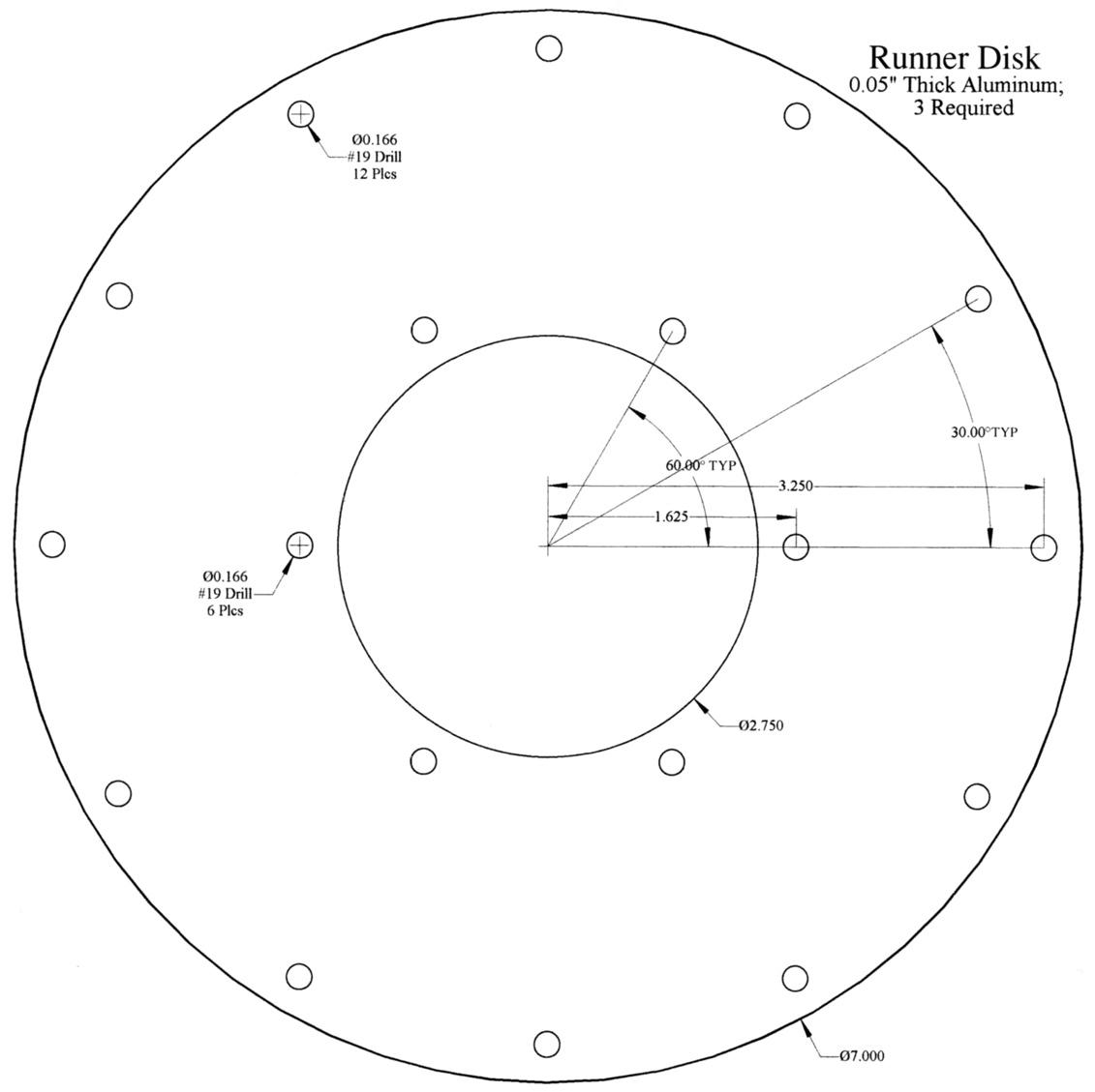
| 3 | Runner Disk | 7.000 dia. x 0.05 | aluminum |
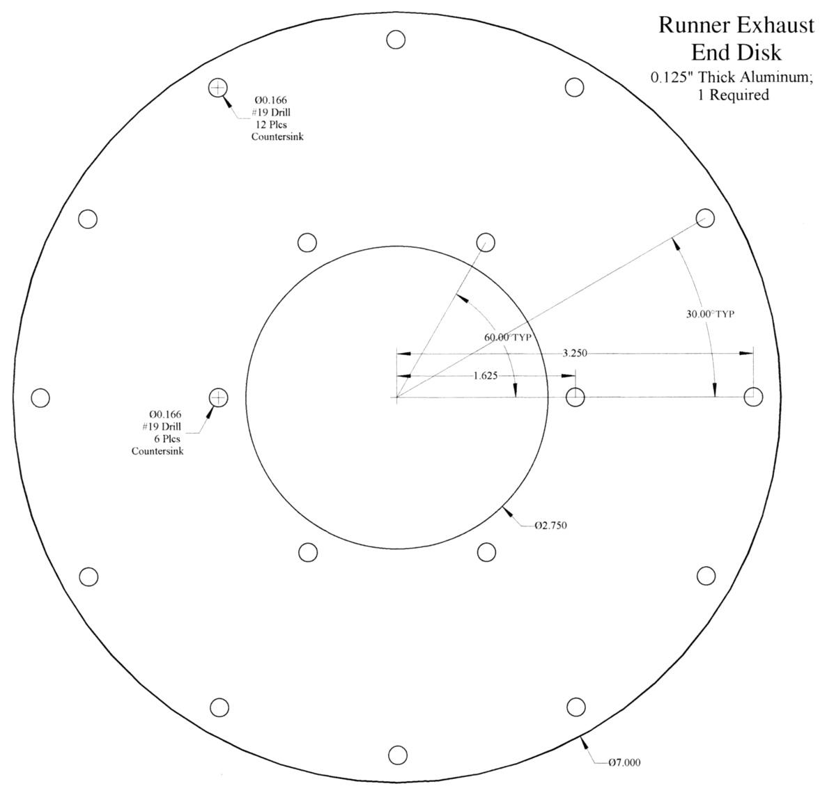
| 1 | Exhaust End Disk | 7.000 dia. x 0.125 | aluminum |
| 1 | Shaft Hub | 2.438 dia. x 0.906 | aluminum |
| 1 | Hub | 1.250 dia. x 1.333 | brass |
| 1 | Shaft | 0.500 dia. x 7.750 | steel |
| 1 | Bearing Frame Runner End | 6.750 x 4.000 x 0.500 | aluminum |
| 1 | Bearing Frame Output End | 6.750 x 4.000 x 0.500 | aluminum |
| 1 | Bearing Frame Top | 4.500 x 4.000 x 0.500 | aluminum |
| 1 | Bearing Frame Bottom | 4.500 x 4.000 x 0.500 | aluminum |
| 2 | Bearing Cup | 1.250 dia. x 0.844 | brass |
| 1 | Tachometer Sensor Block | 1.500 x 1.500 x 1.125 | aluminum |
| 1 | Tachometer Sensor Wheel | 1.500 dia. x 0.563 | aluminum |
| 1 | Nozzle | 0.500 dia. x 3.500 | brass |
| 1 | Runner Cover Plate | 8.000 dia. x 0.125 | aluminum |
| 1 | Valve Body | 1.500 x 1.500 x 2.500 | aluminum |
| 1 | Valve Slug | 1.000 dia. x 1.563 | brass |
| 1 | Valve Actuator | 1.438 dia. x 0.625 | aluminum |
| 1 | Valve Handle | 0.250 dia. x 2.000 | brass |
Purchased Parts
The following table lists all of the parts that were purchased. This also includes the metal stock I didn’t have already on hand. All these vendors have excellent websites and ordering from them is quite painless. Online Metals (www.onlinemetals.com) will custom cut their stock for you. This proved to be quite useful to me as I have no means to cut 8” diameter aluminum stock.
| QTY | DESCRIPTION | PRICE | VENDOR P/N | VENDOR |
|---|---|---|---|---|
| 1 | Optical Sensor | $1.13 | QVB11134QT-ND | Digi-Key |
| 1 | Tachometer Connector (on turbine) | $1.68 | A1301-ND | Digi-Key |
| 1 | Tachometer Connector (on cable) | $1.68 | A1300-ND | Digi-Key |
| 1 | Connector cable clamp | $2.30 | A1330-ND | Digi-Key |
| 4 | Pin (turbine connector) | $0.35 ea | A1324-ND | Digi-Key |
| 4 | Socket (cable connector) | $0.62 ea | A1654-ND | Digi-Key |
| . | Mechanical | Parts | . | . |
| 2 | Steel Ball Bearing | $2.98 | 60355K74 | McMaster-Carr |
| 2 | Timing Belt Pulley, 10 teeth, 1/5” pitch | $5.84 | 6495K711 | McMaster-Carr |
| 1 | Timing Belt, 1/5” pitch, 100XL | $1.98 | 6484K12 | McMaster-Carr |
| . | Metal | Stock | . | . |
| 3 | .050” ALUM SHEET 6061 T-6, cut to 8” square | $12.16 | N/A | Online Metals |
| 3 | 1/8” ALUM SHEET 6061 T-6, cut to 8” square | $17.92 | N/A | Online Metals |
| 1 | 8” ALUM ROUND 6061-T6, cut to 1.625 thick | $64.02 | N/A | Online Metals |
| 1 | 1/8 BRASS PLATE, cut to 8” square | $27.54 | N/A | Online Metals |
Digi-Key: 1-800-344-4539; http://www.digikey.com/
McMaster-Carr Supply Co.: (562)692-5911 (CA); http://www.mcmaster.com/
Online Metals: 1-800-657-0721; http://www.onlinemetals.com/
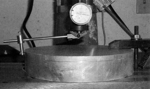
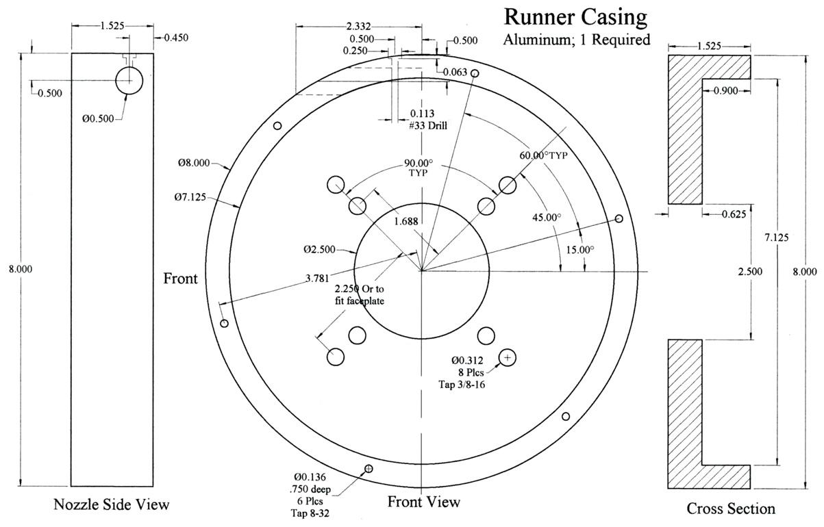
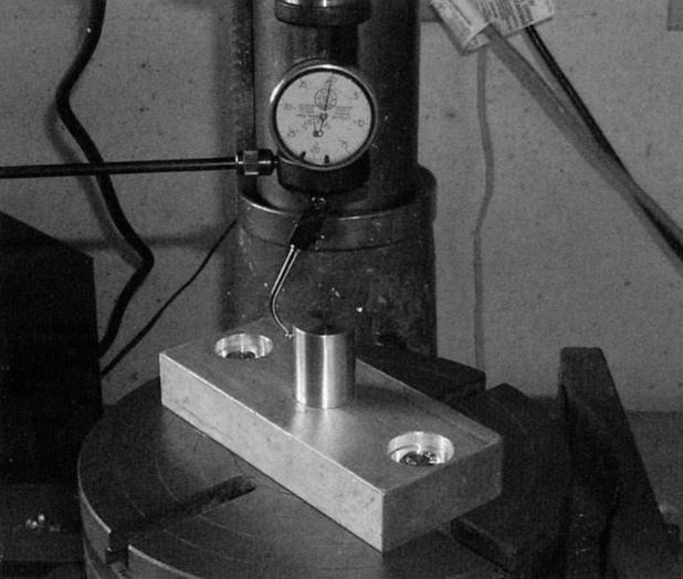
Runner Casing
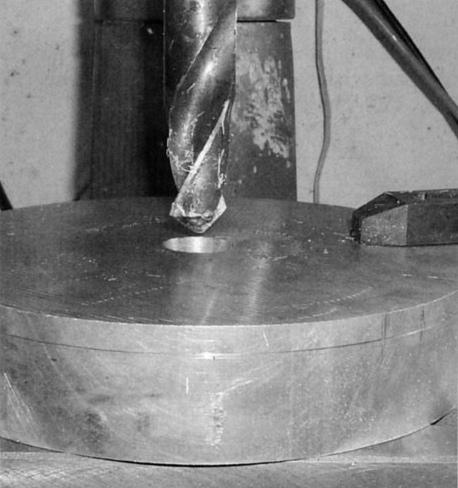
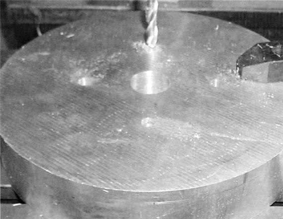
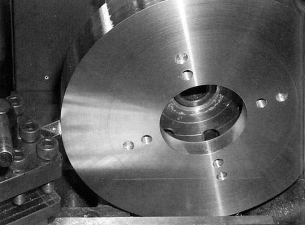
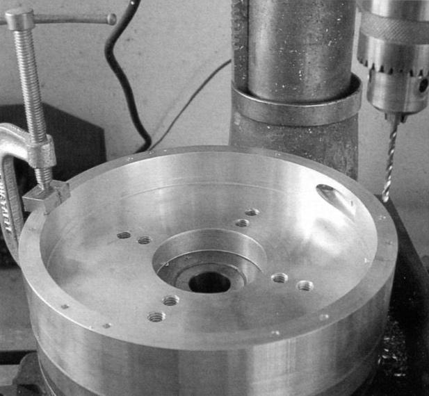
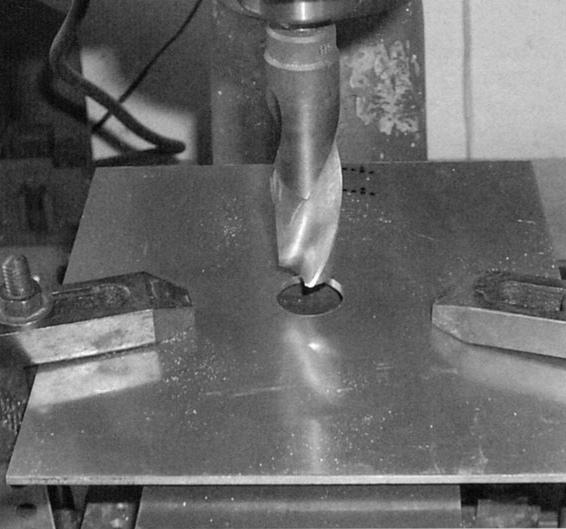
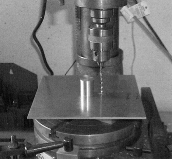
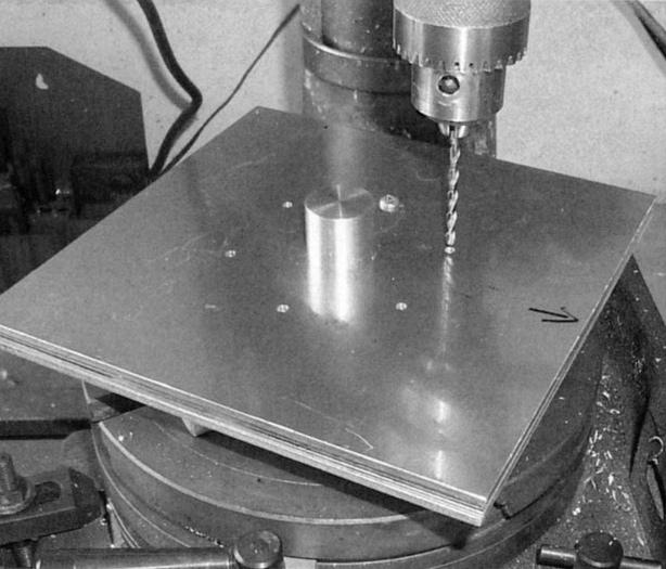
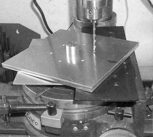
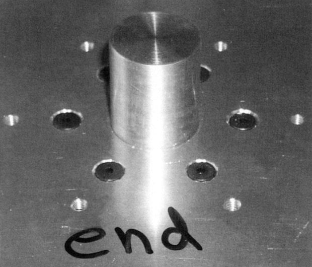
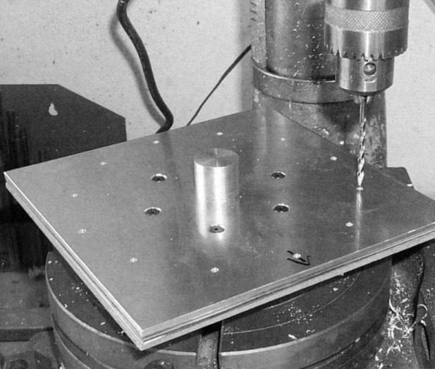
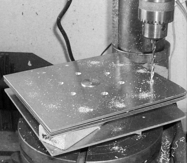
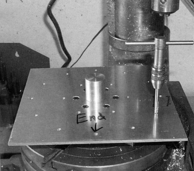
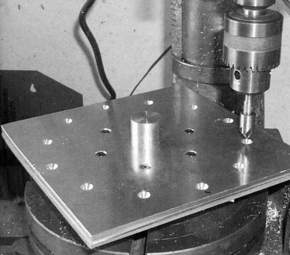
This part begins with the 8” diameter aluminum round mentioned above. Clamp the round to the mill table and center it under the spindle as shown in Photo 1. I found it necessary to make an extension for my coax center finder, which can also be seen in Photo 1. The next step (Photo 2), drills a hole in the center. The initial size is not critical; 0.750” to 1.000” will do. Drill the eight 0.312” diameter holes as seen in Photo 3. Four of the holes are on a 1.688” radius bolt circle; two of these will be used to hold the casing to the bearing frame. I drilled four holes to allow flexibility in attaching the casing to the bearing frame,-you can drill just two of them if desired. The other four holes are on a 2.250” radius bolt circle. These holes are used to clamp the casing to the lathe faceplate. The spacing of these holes should be made to fit your own faceplate. Tap all holes 3/8-16 after drilling through.
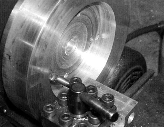
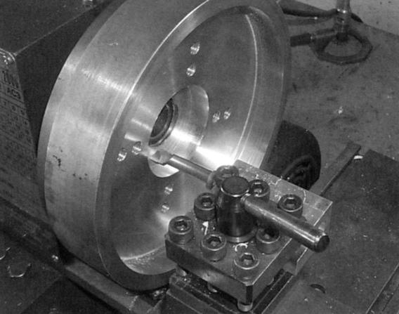
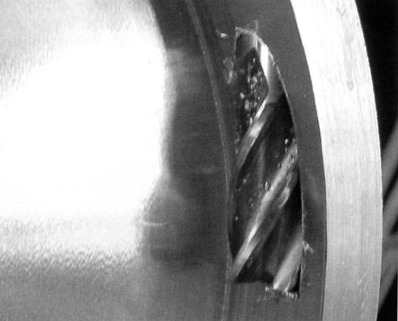
Remove from the mill and use four 3/8-16 bolts to attach the casing to the lathe faceplate. Center the casing using either the central hole previously drilled or the outer edge. Face off the surface, then begin the long process of removing enough metal to make a 7.125” diameter and 0.900” deep hole. Photo 4 shows this process partially completed. Next, bore the central 2.500” diameter hole as deep as possible without actually cutting into the faceplate (Photo 5).
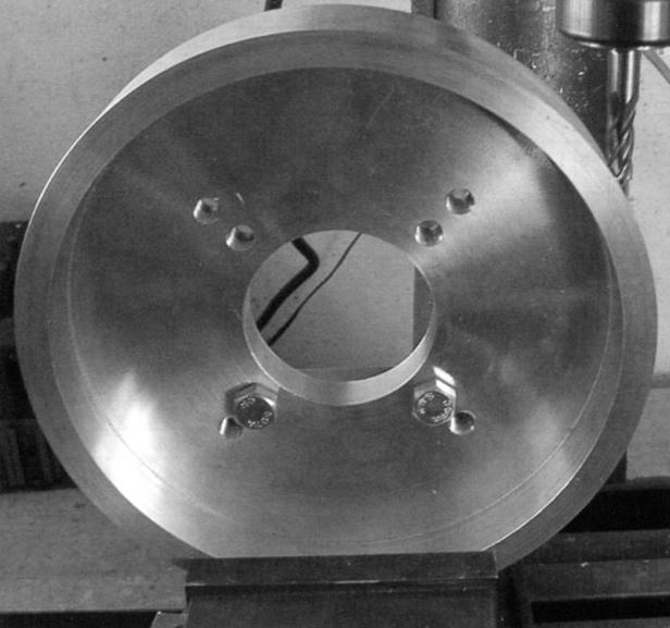
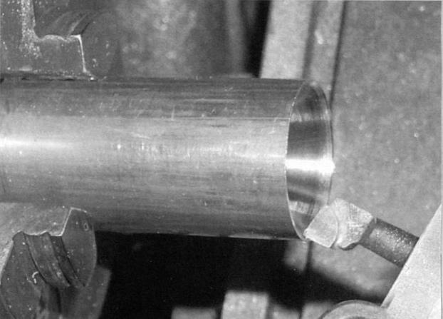
Remove the casing from the faceplate, turn it around, and attach it again. You’ll probably need to use a different, longer set of 3/8-16 bolts. True it up again via the central hole. Take facing cuts until the thickness is 1.525” as indicated on the drawing. Turn the outer diameter down to 8.000”. The round as supplied was slightly bigger than 8” (Photo 6).
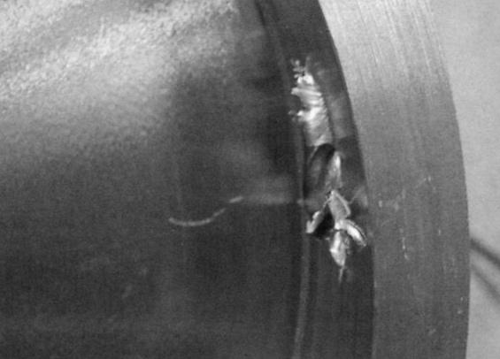
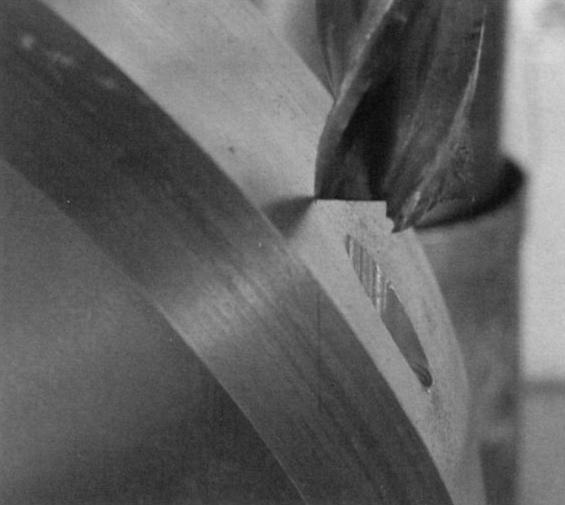
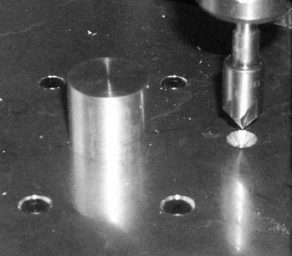
Next, we’ll drill the hole for the nozzle. Transfer the casing back to the mill and clamp in place as seen in Photo 7. Use a pair of 3/8-16 bolts for alignment. Position the spindle 0.450” in from the front edge and 0.500” in from the outer 8.000” diameter edge. Using a 0.375” diameter center-cutting end mill, bore straight down until the mill is cutting a complete circle. Use a 0.350” drill to make a hole as seen in Photo 8. Do not drill any further than shown in the photo - just until the point breaks through. Switch to a 0.500” end mill. Lower the spindle until the flute just makes contact with the runner casing (Photo 9). From this point, bore down 2.332”, as shown in the drawing (Photo 10). This will result in a hole with a flat at the proper depth to hold the nozzle in place.
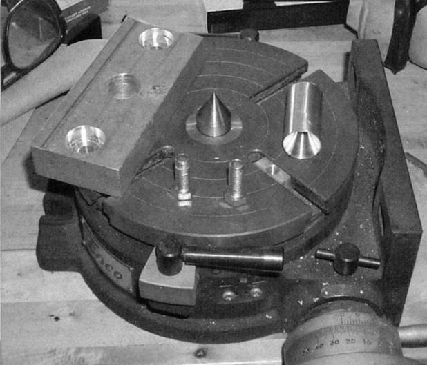
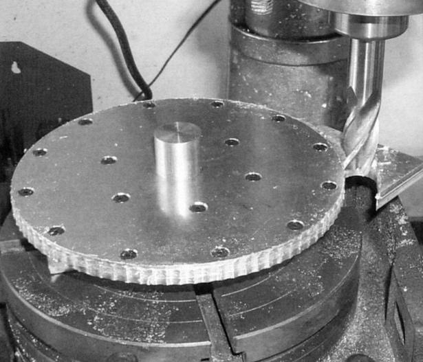
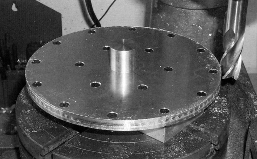
Next, we’ll drill and tap the holes used to attach the runner cover plate. Place the casing on the rotary table. Center the table under the spindle (Photo 11). Now center the casing on the rotary table. Note the angular position of the hole pattern on the drawing. There are six holes spaced 60° apart, and offset 15° from the flat edge of the nozzle hole. Insert a length of .500” diameter rod into the nozzle hole. Using a dial indicator along the rod, move the mill table left and right. Turn the rotary table until the dial indicator shows that the rod is parallel with the X-axis of the table. Note the angular position of the rotary table. Re-center the spindle over the center of the casing/table. Move the table left by 3.781”, the radius of our desired bolt circle. At this point, the nozzle hole will be 90° away from the center of the spindle. Turn the table clockwise by 15°. We’re now in the correct position for the first hole.

Center drill and drill with a No. 29 drill 0.750” deep. Turn the table 60° and repeat. Do this for all 6 holes (Photo 12). Note that in this photo, there’s a set of holes showing how I had to measure three times and cut twice; I hope you get it right the first time!
Runner Disk Tooling
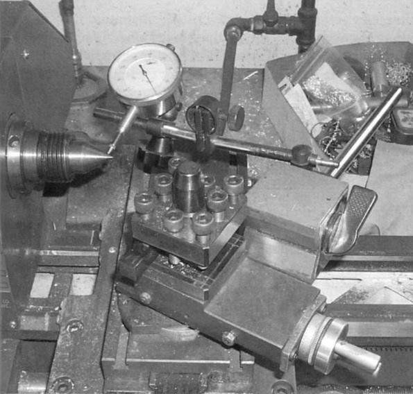
The runner disks require some tooling that is fairly quick and simple to make. The first piece is a length of 1.000” diameter brass rod with a 60° taper in one end to fit a dead center. Place the center in the lathe headstock. Attach a dial indicator to the compound rest. Adjust the rest so it is parallel to the edge of the center (Photo 13). Bore the 60° hole (Photo 14).
The second piece is a rectangle of 0.750” or 1.000” thick aluminum. Bore a hole approximately in the center 1.000” in diameter. Bore holes in a line with the central hole so they will fit your rotary table. Counterbore these holes so the heads of the 3/8-16 bolts will be below the surface (Photo 15). This tooling will be used to hold and align the runner disks for several operations.
Runner Disk Preparation
All runner disks need to have a 1.000” hole drilled in the approximate center. Clamp each of the five disk blanks down and drill, as seen in Photo 16.
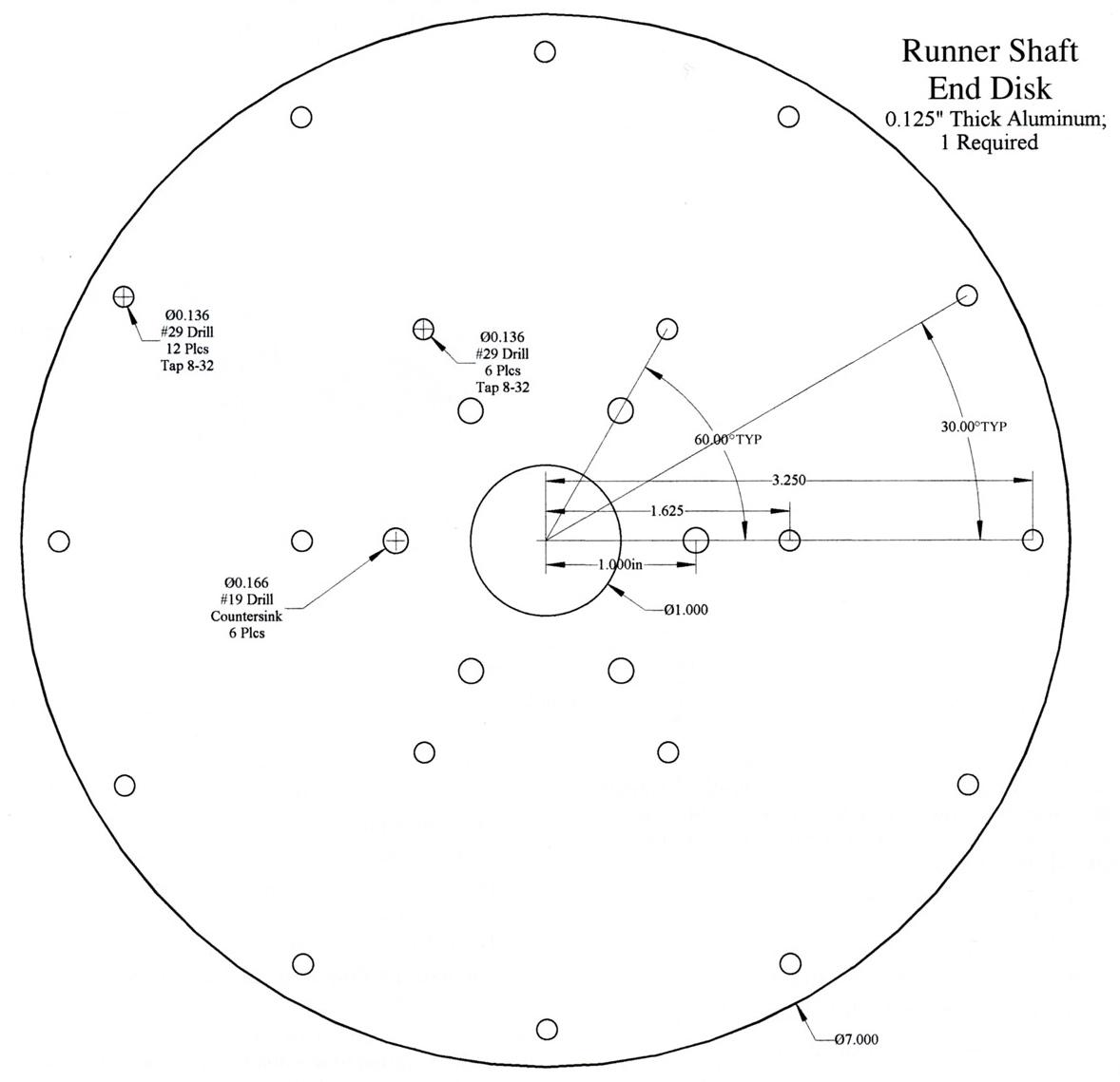
Runner Shaft End Disk
Photo 17 shows the basic setup for the shaft end disk. After placing the dead center in the rotary table (shown back in Photo 15), put the 1.000” brass rod over the center and then slide the aluminum block over the rod. Bolt the block to the rotary table. Now center the rod under the spindle. Place one of the 0.125” thick disk blanks over the 1.000” rod. Set the tables dial to 0°, then move the mill table left by 1.000”. Line the disk blank up roughly square, although this isn’t critical, and drill a No. 29 hole through the blank and into the underlying aluminum block (Photo 18).
Remove the disk and tap the resulting hole 8-32 (Photo 19). Enlarge the hole in the disk blank to No. 19. Place the blank back on the aluminum block and fasten it down with an 8-32 screw. Now drill the remaining five holes with a No. 29 drill spaced at 60° intervals (Photo 20). Countersink each of the six holes (Photo 21), enlarge to No. 19, and attach to the underlying aluminum block with 8-32 flathead screws.
Nicola Tesla [sic] had 700 patents in the US and Europe. His credits include the Tesla Coil, fluorescent light, wireless transmission of electrical energy, remote control, discovery of cosmic radio waves, and use of the ionosphere for scientific purposes. JDR
Runner Disks
The remaining runner disks all need the same sets of holes. Stack the disk blanks over the brass rod as shown in Photo 22. Note that these are in order; three of the 0.050” thick blanks are on top of the first one, followed by a 0.125” thick blank. Label these and mark one edge to keep track of their orientation; this may be seen with the “4” and the arrow in Photo 22. Move the mill table to the left by 0.625”, for a bolt circle of 1.625”. Drill through all disks with a No. 29 drill, similar to this operation on the first disk.
Remove the four top disks and tap the hole in the remaining shaft end disk 8-32. Enlarge the holes in the top four disks to No. 19 and then attach them with an 8-32 screw. As seen in Photo 23, drill the remaining five holes at 60° intervals.
Drill out the No. 29 holes in the top four disks to No. 19.1 found it convenient to use a piece of scrap plastic to prevent drilling out the bottom disk (Photo 24). Tap all No. 29 holes in the end disk 8-32 (Photo 25). Place the stack of four disks back on and countersink all six holes as you did on the end disk (Photo 26).
Make sure the rotary table is back at the 0° position. Move the mill table left another 1.625”, setting us up for another bolt circle of radius 3.250”. As in the previous circle, drill, tap, and countersink the required holes. Note that this circle has 12 holes spaced 30° apart (Photos 27, 28, 29, and 30).
Now we can finally make all the disks round. Rough cut the edge on the rotary table; make sure to leave the disk diameter larger than 7.000” to provide some extra material (Photo 31 and 32).
Next time, we’ll continue with the runner shaft hub.