Plans
Tesla's Lightning Generators
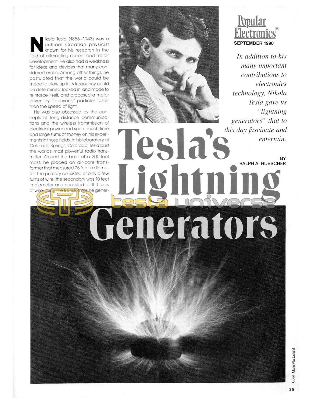
In addition to his many important contributions to electronics technology, Nikola Tesla gave us "lightning generators" that to this day fascinate and entertain.

Nikola Tesla (1856-1943) was a brilliant Croatian physicist known for his research in the field of alternating current and motor development. He also had a weakness for ideas and devices that many considered exotic. Among other things, he postulated that the world could be made to blow up if it's frequency could be determined, locked in, and made to reinforce itself, and proposed a motor driven by "tachyons," particles faster than the speed of light.
He was also obsessed by the concepts of long-distance communications and the wireless transmission of electrical power and spent much time and large sums of money on his experiments in those fields. At his laboratory at Colorado Springs, Colorado, Tesla built the world's most powerful radio transmitter. Around the base of a 200-foot mast, he placed an air-core transformer that measured 75 feet in diameter. The primary consisted of only a few turns of wire; the secondary was 10 feet in diameter and consisted of 100 turns of wire. Using the transformer, he generated on the order of 100-million volts. From the 3-foot copper ball on the top of the mast, bolts as long as 100 feet leapt; Tesla had created the first manmade lightning. And with that "Tesla coil," he was eventually able to light a bank of 200 incandescent light bulbs from a distance of 26 miles.
Unfortunately, Tesla's ideas were considered nonsense by most of the reputable scientists of his time. Even today, he receives little recognition for his many important contributions to electronics and electricity. Chief among those, of course, is his development of the AC power-distribution system, which is still in use today.
And, of course, there is the high-voltage generator he used for his Colorado Springs experiments. Scaled down versions of that Tesla coil are popular among experimenters and hobbyists. When treated with care, they can provide hours of fun.
Building a Tesla Coil
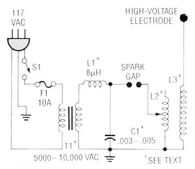
Take a look at the schematic of Fig. 1. Don't let its simple appearance fool you. For the circuit to work, resonance has to be achieved and that is the catch. When dealing with high-frequency voltages (in the 200,000-volt range) exact capacitance, voltage, and frequency measurements can be difficult and dangerous to obtain without apparatus that is too expensive for the average hobby lab. Without that data, resonance formulas are of little help, and trial-and-error-methods can lead you a long way off the path of success.
Our purpose here, then, is to provide you with a framework that will help you develop your own working Tesla coil; without that framework, it could take you a long time to develop a good model. With all the necessary materials on hand (more on that shortly), a Tesla coil could be built in a couple of evenings. More likely, however, it will take you over a week of evenings especially if you have no experience in winding long coils of thin wire without overlaps.
Before we go much further, we must make clear that this article is intended for experimenters. Other articles that have appeared in Popular Electronics and elsewhere have given step-by-step instructions for building a Tesla coil of a particular design. Our intention here is to provide a starting point for you to develop a Tesla coil of your design. We will present some design criteria, point out some of the pitfalls that we discovered the hard way, give some hints that will help you along the way, and show you some interesting experiments to try. The rest is up to you.
Principles of Operation
As the schematic shows, a line transformer (T1) with a 5000- to 10,000-VAC secondary energizes the circuit.
A heavy-duty hash choke (L1) can be used to keep the high-frequency electrical energy from entering the AC line and interfering with TV's, VCR's, computers, etc. It is not always needed; we do not use one with the type of transformer that will be described later on when we discuss specific components.
A spark-gap driven resonating circuit (capacitor coil) produces ragged high-frequency peaks that are extremely well-suited to induce high voltages in the secondary air-wound coil (L3). Depending on the diameter of the secondary coil, it's inherent capacity can vary greatly, effecting its resonant frequency. For the maximum transfer of energy, and hence best performance, the primary circuit must be tuned to match that resonant frequency as closely as possible. That is done via a series of taps in the primary coil (L2) as well as by adjusting the setting of the spark gap. Properly tuned, a Tesla coil as described here will deliver a high-frequency output in the range of 200,000 volts. Such a voltage will produce a corona - a ball of blue-glowing plasma (glowing gas) - or sparks up to 8-inches in length. We will shortly describe a series of marvelous experiments that can be conducted with your Tesla coil.
Warning!!! This article deals with and involves subject matter and the use of materials and substances that may be hazardous to health and life. Do not attempt to implement or use the information contained herein unless you are experienced and skilled with respect to such subject matter, materials and substances. Neither the publisher nor the author make any representations as to the accuracy of the information contained herein and disclaim any liability for damages or injuries, whether caused by inaccuracies of the information, misinterpretations of the directions, misapplication of the information or otherwise.
Safety Considerations
As mentioned previously, the primary winding is energized by a line transformer that delivers 5000-10,000 volts AC. Such a transformer is potentially deadly and should be treated with utmost care. It would be more than prudent to house that transformer in an insulating plastic case to protect yourself and curious onlookers.
Despite its 200,000-volt potential, due to the high frequencies involved, the secondary winding presents somewhat less danger. However, while high-frequency current will not penetrate the human body, arcs will find their way to ground on the surface of the skin, causing burns. Strangely, in our experience no blisters have formed, just little black holes - and we've had our fair share of them!
The spark gap produces ultraviolet radiation that can affect the eyes. So, it should be housed or shielded in some way. You can use a plastic project box of sufficient size for that. The author has also used pieces of PVC pipe to cover the spark gap.
Ionization of the air takes place at the spark gap and the high-voltage electrode. That generates significant amounts of ozone that can be toxic, especially when concentrated, so a well-ventilated work area is a requirement. Further, the device should be turned on for a short period of time only.
Finally, even though a hash suppressor is used, air transmission of electromagnetic impulses from the coil will interfere with radio (evident as hum) and TV reception (appearing as white lines), and cause peaks on recorders or other sensitive nearby equipment.
Components
Perhaps the biggest challenge in building a Tesla coil is gathering the needed parts. High-voltage gear is not as common as it used to be, and usually can not be obtained from traditional hobbyist sources. Here are some hints to help make your hunt go a little smoother:
Line Transformer. In the author's experience, the best type of transformer for this application is an oil-burner ignition transformer. If you cannot find one in a scrap yard, ask a plumber who installs oil burners. Normally these transformers have a 117-VAC primary and two 5000-VAC secondaries that can be used singly; they can also be used in series (if properly phased) to give you a full 10,000 VAC at roughly 20 mA.
Once again, treat these high-voltage transformers with all due respect. They can be deadly if you are grounded. I make it a point to stand on a dry floor with a cushion under my feet when working on high-voltage projects of any type whose performance is unknown or unpredictable, and Tesla coils that are under development certainly fall into that category.
Also useful may be an old TV-technician's trick: That is, to keep your left hand in your pocket whenever you work with high voltages. That way you can never be connected from high voltage to ground by way of hand-body (heart)-hand. By the way, that technique was first used by Nikola Tesla!
Another possibility is to use a neon-tube transformer, the type used to illuminate signs. They normally have a 117-volt primary and two 3500-VAC, 50-mA secondaries that can again be connected in series. With neon-tube transformers, a hash choke is a good idea.
There are a few other ways to excite a Tesla coil. One is to use an automotive ignition coil. To do that, though, you need an interrupter circuit. A suitable set up was discussed in the "Solid-State Tesla Coil," which appeared in the October, 1988 issue of Hands-on Electronics.
You can also use a TV high-voltage supply to drive a Tesla coil. It works, but the coil is unlikely to be a spectacular performer.
Capacitor. Capacitor C1 is a .003-.005 uF (3000-5000 pF) ceramic unit with a voltage rating that's suitable for your transformer. That means if your transformer is outputting 10,000 VAC, you need a capacitor with a rating of at least 15,000 WVDC.
Such capacitors do not grow on trees, and can be expensive even when found. The author tried to get around that problem by building a unit from scratch. After some pre-trials with metal plates and rubber mats, a home-built unit fashioned from 1-inch thick, table-top sized, styrofoam sheets with aluminum foil glued to both sides yielded the needed capacitance and voltage-handling capability. Unfortunately, it also yielded a capacitor that was three-feet tall!
In all honesty, building your own capacitor should only be tried as a last resort, unless you are the sort that enjoys experimenting with such things. If so, you'll probably want to get hold of the latest catalog from Lindsay Publications (P.O. Box 12, Bradley, IL 60915-0012). Their unusual collection of books on a variety of electrical subjects includes a number that are dedicated to high-voltage experimentation. Several of those offer information on building your own capacitors.
Turning to more conventional alternatives, high-voltage ceramic "doorknob" capacitors are ideal for use in Tesla coils. Those capacitors were once commonly used in TV high-voltage power supplies, but that is no longer true. Some full-line industrial suppliers do still stock them, however, but they are very expensive. For instance Newark Electronics (stores nationwide) lists appropriate-valued units with ratings as high as 40,000 WVDC in their catalog, but they can run to over $40 each (though lower-rated units are a bit less). A cheaper solution would be to salvage one from an early (1950's) TV set.
Another solution, and the one the author uses, is to use a series-parallel combination of ceramic capacitors to yield the needed value. For instance, by connecting four .01-uF, 8000-WVDC ceramic capacitors in series, and paralleling that combination with another string of four series-connected, .01-uF, 8000-WVDC ceramic capacitors, a .005-uF, 32,000-WVDC unit is created. Of course, there are many other combinations that will also work.
Primary Coil. Winding the primary coil is fairly simple. Place 10 turns of heavy-gauge (#10 - #12) wire on a piece of 8-inch diameter plastic or PVC pipe. As you are winding, twist a small pigtail every turn or two to act as a tap; the more taps the better. The turns can be held in place by insulating tape or candle wax.
Secondary Coil. The author has wrapped dozens of secondary coils. Their diameters varied from ¾- to 4-inches, and have ranged from 400 to 7600 turns and heights from 1 to over 6 feet. Some were built in sections and could be mounted one on top of the other. However, considering size, effort, and efficiency, the best ones were wrapped on a 10-12-inch length of 3½-inch O.D. PVC pipe. Wind about 400-500 turns of #24 lacquered or magnet wire. The turns must not overlap or efficiency will suffer severely.
To make the task of winding go much smoother, clamp a broomstick into a vise horizontally, place the PVC pipe over it, and turn the pipe with one hand while guiding the wire with the other. The dispensing wire coil must turn freely. Pressure must be applied to the last turn at all times, but pauses are possible if you keep a piece of insulating tape ready to secure the last turn and, with a second piece, the last 10-20 turns.
Airplane glue or rubber cement can be used to secure the wire permanently at the ends and in spots along the way. When completed, several coats of paraffin wax, molten candle wax, or bees wax should be used to cover the entire coil, especially at the high-voltage end. That will suppress corona discharge in places where it is not wanted.
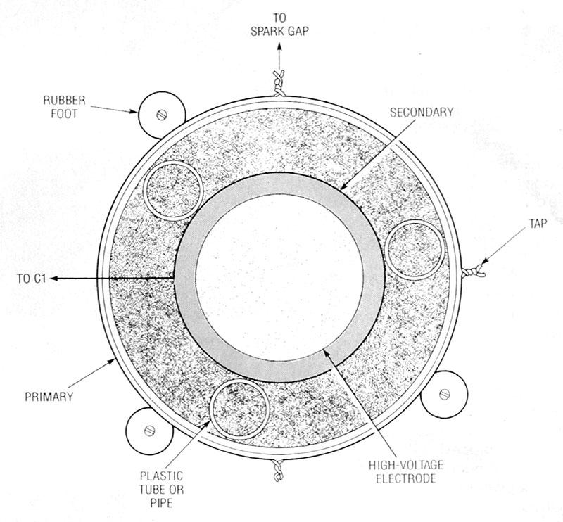
The coil is assembled by placing the secondary within the primary as shown in Fig. 2. The base of the coil is grounded. The high-voltage end is fitted with an end-cap that serves as an insulator/high-voltage-electrode mount. Details for a homemade end-cap fashioned from a plastic drinking cup, candle wax, and a doorknob is shown in Fig. 3; the door knob serves as the high-voltage electrode.
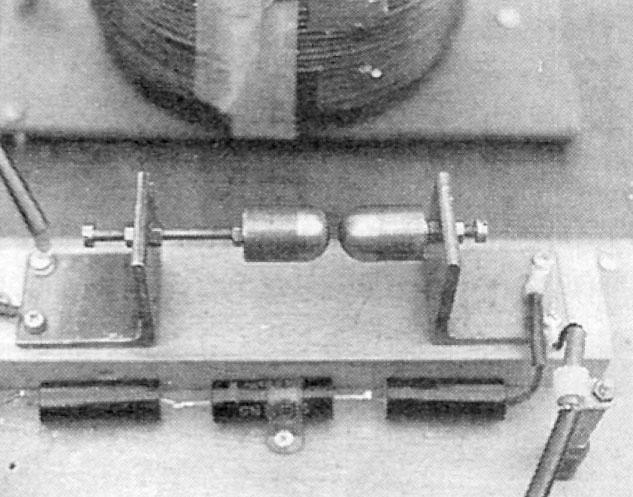
Spark Gap. The spark gap can be formed in many ways. The author's units use two 1-inch pieces of 1-inch diameter aluminum or brass rod. After the pieces are cut to size, one end of each is machined to a smooth ball-like surface on one side and drilled and tapped on the other for mounting in a stand with bolts and nuts for adjustment. The author has also made spark gaps by soldering large, steel ball bearings to carriage bolts.
Hash Suppressor. A hash suppressor or choke will keep impulses from your coil from getting into the electrical system from where they can be picked up by a TV, VCR or other recorder, or home computer. If no commercial product can be found, a 4-inch ferrite bar can be wrapped from beginning to end with heavy lacquered wire.
You may want to also try some EMI (electromagnetic interference)-reduction techniques on the primary side of the transformer. You could use a commercial line filter, for instance, but the cheapest and easiest trick to try is to wrap the line cord through an iron torroid-coil form several times.
Note that using a hash choke will not eliminate the transmission of electromagnetic impulses by air. Only a Faraday cage can accomplish that.
Adjustment. There really isn't too much to do to get your coil up and running. Basically, the different primary taps must be tried out and the distance of the spark gap must be adjusted for maximum output as can be seen by size of the corona and sparks.
If something doesn't seem right, pull the plug before attempting any troubleshooting. Also, never adjust the spark gap or the taps while power is applied to the circuit. Always power down between adjustments. Remember, a Tesla coil is a high-voltage device that could cause serious damage to life and limb if you don't treat it with the proper respect.
Now that we have a Tesla coil, let's see what kind of interesting things we can do with it.
Experiments
By varying the shape of the high-voltage terminal, you can vary the nature of the coil's discharge. Using a round high-voltage terminal as already discussed, charges can distribute themselves over a relatively large area and corona discharge is held to a minimum. Instead, long sparks and streamers can be seen emanating in all directions. Note that more impressive sparking can be obtained on dry rather than humid days.
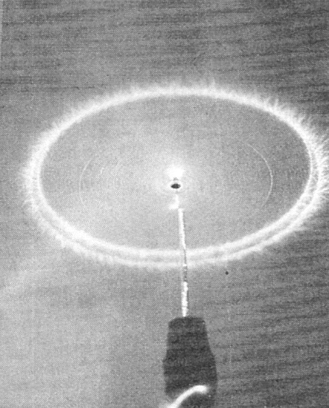
However, observing a corona discharge can also be exciting and interesting. That discharge consists of a ball of blue-glowing plasma with sparks moving outward from the center. It occurs best when the high-voltage terminal ends in a piece of wire or a pointed object rather than the ball shaped terminal normally used.
Grasp a light bulb (the 200-watt transparent type is best) by the glass envelope and bring the base near the high-voltage electrode. Arcing from the filament to the inside of the envelope at the points your hand touches will form a spectacular display similar to that produced by the "Lightning Bulb" shown in the Feb. 1989 issue of Popular Electronics. The glass envelope diminishes the possibility of burns.
Fluorescent tubes will flicker and glow if brought to within 6 feet of a strong, operating Tesla coil. That's because the electromagnetic radiation excites the diluted rare gas in the tube. If one end of a fluorescent tube is touched to the high-voltage electrode, the tube will light up brightly. This means it conducts, so under no circumstances should you touch the other end; it will arc and burn you.
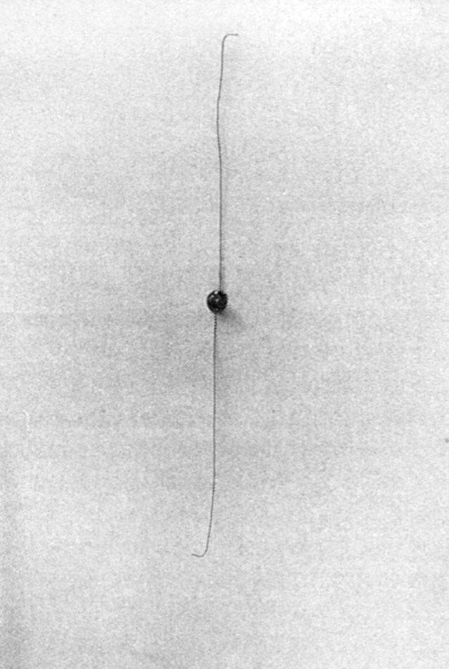
Build a little propeller using a brass rivet as a compass-needle-like bearing and two pieces of lightweight wire. Make opposing 90° bends at the ends of the wire. Using a wire or other pointed object as the high-voltage electrode, balance the rivet on the electrode. Apply power to the Tesla coil and watch your propeller spin.
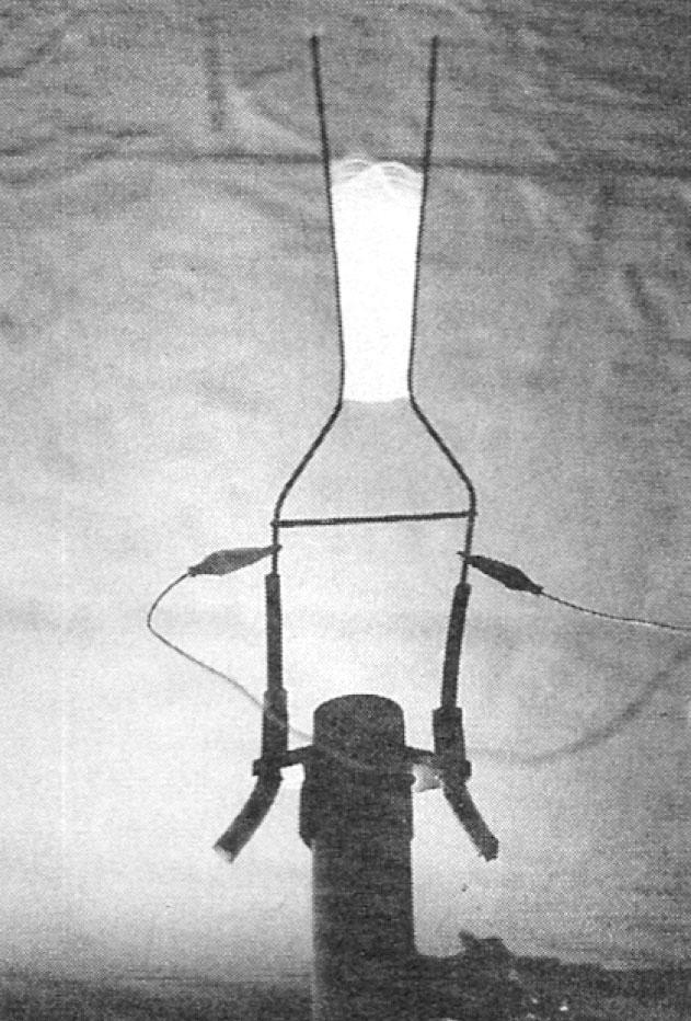
You can use a Tesla coil to power a "Jacob's ladder." Mount two heavy-gauge, uninsulated wires so that they are isolated from ground and each other, and so that they diverge (angle away from each other). Using jumpers, connect one wire to the Tesla coil's high-voltage electrode and the other to ground. Power up the Tesla coil and a spark will form at their closest point. The spark's own heat will carry it upward until the distance becomes too large and it opens. When that happens, a new spark forms at the bottom.
There are many other experiments that you can try. For instance, plasma globes and Plucker tubes (evacuated glass tubes made conductive by the addition of small amounts of rare gases; at one time, these were used by "healers" against all sorts of diseases) can be driven by Tesla coils. However, whatever you try, remember to treat your Tesla coil with respect.
Parts List for the Tesla Coil
C1 - .003-.005-uF, 15,000-WVDC, ceramic capacitor, see text
L1 - 8-uF, 10-amp, heavy-duty hash choke, see text
L2 - 10 turns, 10- to 12-gauge wire, see text
L3 - 400-500 turns, 24-gauge magnet wire, see text
T1 - 5000-volt, 20-mA, dual-secondary, oil-burner transformer
F1 - 10-amp fuse
S1 - SPST power switch
PVC pipe (see text), 3-terminal AC line cord, 1-inch diameter brass or aluminum rod stock, metal doorknob (for high-voltage electrode), plastic-cup, candle wax, paraffin wax, wire, solder, hardware, etc.