Plans
Voltage Doublers
Voltage doublers are an easy and inexpensive way to experiment with high voltage.
If you've been looking for a way to generate high voltage, you've undoubtedly run across the voltage doubler. Voltage doubling using diode-capacitor combinations is a common practice. However, whole banks of doublers, called cascades, can also be used for producing extremely high DC voltages from moderate to high AC voltages. Such high DC voltages may be needed for TV sets, lasers, air purifiers, industrial smoke-stack dust removers, negative-ion generators, and, of course, for experimenting, on which we'll concentrate here.
Half-Wave Doubler
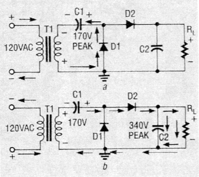
Figure 1 shows a half-wave voltage doubler; we'll assume that C1 and C2 are initially discharged. During the first half-cycle shown in a, the upper input terminal is positive and the bottom negative, so D1 conducts and C1 charges to about 170 volts peak. Diode D2 can't conduct, since it's back-biased, so C2 discharges through RL. In the second half-cycle (b), the analysis is similar, except that D2 conducts and C2 charges.
The circuit is really a transformerless voltage amplifier. While T1 can provide isolation, as well as increase the AC voltage initially going into the doubler, the amplification due to the doubling action would occur without it. When the polarity reverses, both the input voltage and the charge across C1 are in series like two batteries, producing about 340 volts peak. One problem, though, is that a half-wave doubler can't be used with a load that draws much current.
Full-Wave Doubler
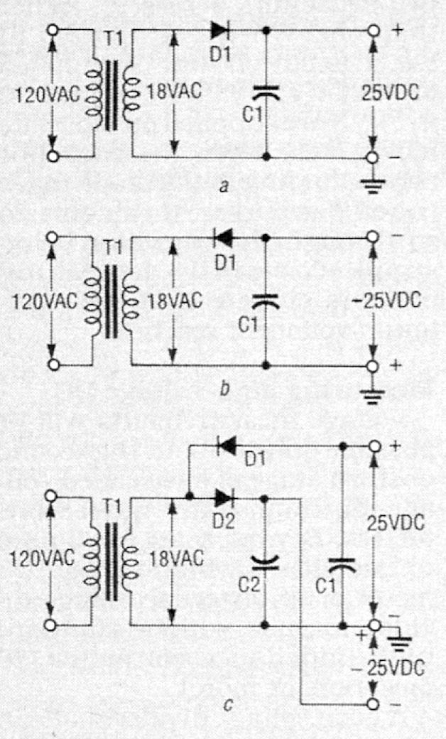
Let's see how a full-wave voltage doubler is related to and built from both positive and negative half-wave rectifiers. Figure 2-a shows a half-wave rectifier with a positive output, Fig. 2-b shows the same version with a negative output, and Fig. 2-c shows the two combined into a full-wave voltage rectifier.
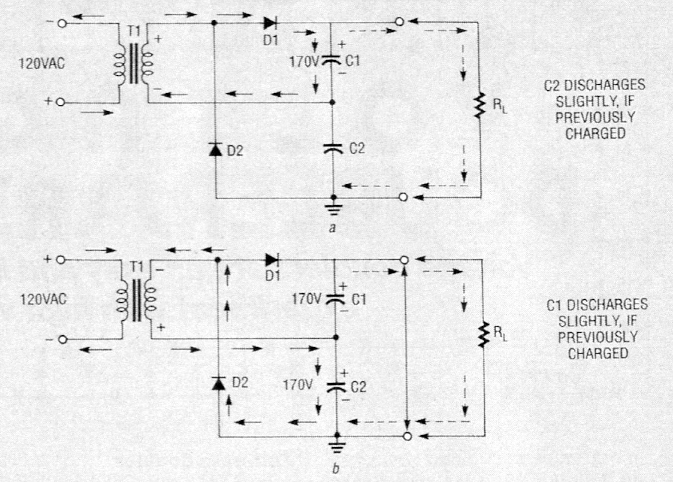
The full-wave voltage doubler shown in Fig. 3 has been redrawn for greater clarity; it has better regulation than a half-wave version, and is easier to filter. The circuit produces nearly double the peak AC voltage of 170 volts, or about 340 volts peak across RL. For the first half-cycle (a), D2 is cut off and D1 conducts, so that VC1 equals approximately 170 volts DC. On the next half-cycle (b), the positive voltage is replaced by a negative voltage, so D2 conducts and D1 is cut off. RL, goes across C1 and C2 in series, effectively creating a doubled level of about 340 volts DC.
Warning!! This article deals with and involves subject matter and the use of materials and substances that may be hazardous to health and life. Do not attempt to implement or use the information contained herein, unless you are experienced and skilled with respect to such subject matter, materials, and substances. Neither the publisher nor the author make any representation as for the completeness or accuracy of the information contained herein, and disclaim any liability for damages or injuries, whether caused by or arising from the lack of completeness, inaccuracies of the information, misrepresentations of the directions, misapplication of the information, or otherwise.
Unlike the half-wave voltage doubler, the full-wave version has two capacitors across RL rather than one. Whereas C1 shown in Fig. 1 is cut off and unsupplied for half of every cycle, C1 and C2 in Fig. 3 are supplied on alternate half cycles. When the capacitor corresponding to the diode that's cut off discharges, it can only do so through the capacitor being supplied, slightly decreasing both its current and the maximum voltage it reaches.
Measuring High-Voltage DC
Voltage measurements will be possible only to about the second or third stage of a cascaded voltage doubler with most voltmeters. Beyond that, you'll need to use either a high-voltage DC meter or an external voltage divider for use with a standard high-impedance voltmeter (10 megohms or more).
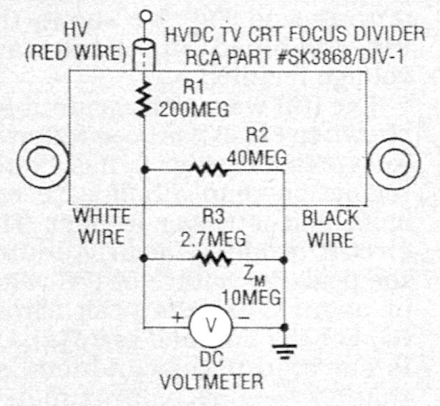
A good voltage divider that can be used for the purpose of high-voltage measurements is the RCA SK3868/DIV-1, a high-voltage DC divider; it's used in TV's to reduce the final anode voltage going to the CRT to the level required for the focus voltage. It consists of resistors R1 (200 megohms) and R2 (40 megohms) in series, as shown in Fig. 4. There are three leads, one for the free ends of each resistor, and the other at their juncture. If you put both a 10-megohm meter (shown as ZM in Fig. 4) and a 2.7-megohm resistor (R3) in parallel with the 40-megohm resistor (R2), you can achieve almost exactly 100:1 range multiplication, for a full-scale deflection of 20 kilovolts DC.
Cascaded Voltage Doublers
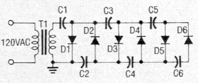
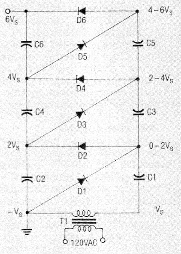
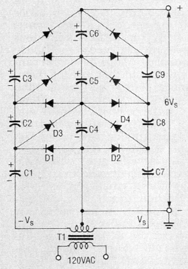
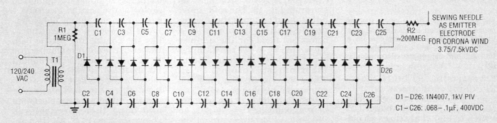
Figures 5 - 8 show four additional voltage doublers. The one shown in Fig. 5 is the most straightforward. If you build it, use 1N4007 diodes with peak inverse voltage (PIV) ratings of 1 kilovolt for D1 - D6, and 0.068 - 0.1 uF capacitors with working voltages of 400 volts DC. Figure 5 is electrically identical to the one in Fig. 6, so keep that in mind if you should come across either format. Figure 7 shows an extended version that's better stabilized for moderate-current applications; its called either a Cockcroft-Walton or Greinacher cascaded voltage doubler.
You can use a sewing needle as an emitter for the doubler shown in Fig. 8 to generate "corona wind." That will sound like a hissing noise. (We'll show you how to demonstrate the "wind" later on.) The circuit delivers 3.75 kilovolts DC when powered from 120 volts AC, or 7.5 kilovolts DC when powered from 240 volts AC.
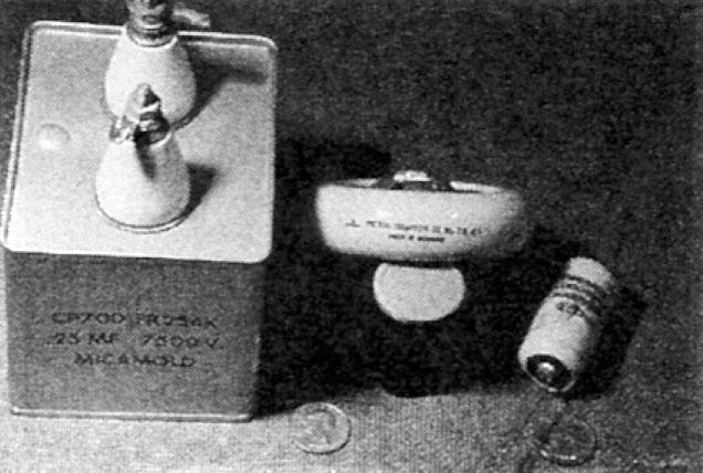
The output of a cascaded voltage doubler should be terminated with no less than 200 megohms, and only then be allowed to extend beyond a protective plastic case, for safety. Voltages as high as 5 megavolts DC have been generated using cascaded voltage doublers, especially when operating in a pressurized atmosphere. The biggest advantage to using voltage doublers is that they use inexpensive low-voltage parts. Otherwise, if all the parts had to be of the high-voltage variety, you would have to use expensive and rather large capacitors like the one shown in Fig. 9.
If you have problems with the circuit in Fig. 8 (or any other high-voltage circuit), you must discharge every capacitor (we'll tell you how in a minute) before you check for malfunctions. When examining the circuit for problems, closely check the solder connections, and then the diode directions and continuity. The 1N4007's should have a resistance of 1.1K when forward-biased and be open when reverse-biased, while the capacitors should all have infinite resistance.
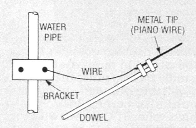
To properly discharge capacitors, build a discharging wand like the one shown in Fig. 10. Use a 2-foot wooden (or plastic) dowel, and connect a stiff wire tip (piano wire works well) to a cold water pipe as earth ground with a good electrical connection. Discharge all capacitors twice, since they generally either hold charge, or tend to recharge from other capacitors. Don't use an AC line ground or chassis ground instead of an earth grounded water pipe, or you may blow a fuse or damage parts.
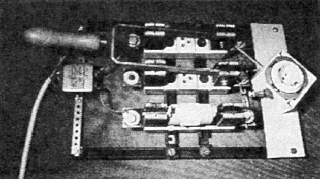
Figure 11 shows a switch for high-voltage DC that you can use with any of the cascaded voltage-doublers shown here; standard switches may present a shock hazard. Also, use an electromagnetic interference (EMI) line filter like the one seen at left in the photo to keep high-voltage DC out of house wiring, and to prevent shock from static charge. The EMI filter is from Corcom Corp. (1600 Winchester Road, Libertyville, IL 60048, tel. 312-680-7400), Model 2061 is rated at 20 amps, 250 volts, and 50-400 Hz. The high-voltage DC switch in Fig. 11 also uses an old 100-amp fuse box, shown on the right; it may look like an antique, but it will prevent any shocks.
When you build a cascaded voltage doubler, you can encase the circuit in pure paraffin oil or candle wax to reduce the chances of getting shocked. It will also minimize corona loss, so the high-voltage DC arrives where it's needed. Figures 12 and 13 show a typical ladder-type voltage doubler before and after being sealed in wax.
Experiments
There are many experiments that can produce observable effects due to the high-voltage DC produced by voltage doublers.
- With a high-voltage emitter pointed at a ground plate (used to attract ions), with a burning candle placed in between them (see Fig. 14), you'll see the candle flame deflect toward the metal plate.
- You can make a rotor for an ion motor, using a light pivot made from a rivet with thin, stiff wire (like piano wire) attached, as shown in Fig. 15. The rotor must be balanced on top of the sewing-needle emitter (much as in a compass) used for the doubler shown in Fig. 8. (We ran a similar construction project in Radio-Electronics, February, 1991.) When powered up, the rotor will spin and a hissing sound will be heard. Both ends of the wire are bent at opposite right angles, so the emitted electrons propel the wire in a circle. You should sharpen both ends of the rotor wire to provide a sharp surface good for corona generation and electron emission. The sharpened ends will have a small radius of curvature (a tight curve or bend), giving rise to a highly distorted electric field at its surface. The high electric field is what tends to ionize air molecules in the vicinity.
- Another experiment you could try involves holding a fluorescent tube near the emitter. The tube will glow, but be careful not to touch the terminals on the ends, or you'll get a shock.
- Lines of force of an electrostatic field can be demonstrated by placing the electrodes (the high-voltage DC output and ground) in a tray covered with castor oil containing some farina. The farina will produce the pattern of the electric field lines; similar to iron filings shaken lightly on a piece of paper in the presence of a bar magnet.
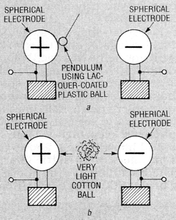
- If you place two round door knobs on insulated stands made from plastic cups filled with candle wax, and then charge them, then a plastic ball suspended from a string will be drawn to and touch the positive electrode, and fall back to center when the spheres are discharged (see Fig. 16-a). A plastic ball coated with conductive lacquer swings toward the positive electrode like a pendulum; when the ball and doorknob touch, the ball becomes positively charged, so they repel one another. It then swings toward the negative side, absorbs electrons, becomes negatively charged, and is repelled back to the positive. The process repeats indefinitely as long as the high-voltage DC is present, and it will continue to operate for some time after it's shut off. The charge exchange is slow, and there'll be arcing at the positive electrode.
- A grounded metal ball alternates between both electrodes, like the conducting plastic ball. However, the arcs are smaller due to its greater weight, and should be observed at both ends, but more on the positive side.
- A light cotton ball should be drawn to the positive electrode and hang there by itself, as shown in Fig. 16-b. It's then repelled 0.5-inch toward the negative electrode, and the process should repeat indefinitely.