Plans
Jacob's Ladder
A climbing electric arc has held the imagination of science-fiction fans as the symbol for an eerie laboratory!
In many sci-fi and horror flicks, especially the stock "Frankenstein" variety, along with weird sound effects and the like, movie producers always feature the fantastic visual effects produced by Tesla coils, Van de Graaff generators, and Jacob's Ladders. Of those three devices, the Jacob's Ladder is the easiest to build. With a low-current neon-sign transformer, a converted flyback transformer, converted auto spark coil, or other similar transformer, you can whip together your own Jacob's Ladder in less than an hour. Because the ladder is so simple, there's no need for a detailed parts list or a schematic. We tell you how to build one as we reveal the theory of operation.
Getting started
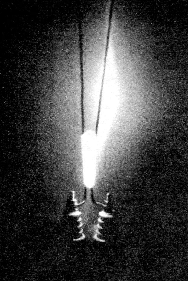
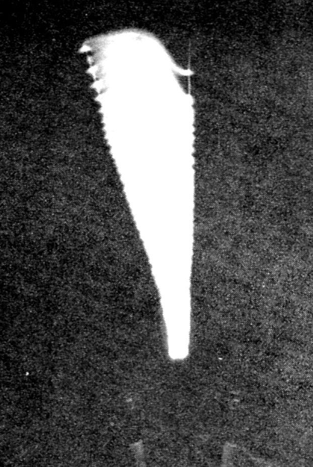
As we can see in Fig. 1, a Jacob's Ladder provides a fantastic visual effect. A beautiful electric arc hisses its way up two diverging wires, providing a fascinating and downright scary effect. The arc starts at the smallest distance between the vee electrodes (Fig. 1-a), and "walks" up the widening gap toward the top of the electrodes (Fig. 1-b).
Why does the arc walk up the vee electrodes? You would expect that when the arc starts to jump across the narrow gap at the bottom of the electrodes, that it would stay there where the electrical resistance between the electrodes is lowest. What actually happens is that the arc heats the air it passes through, causing it to rise. Because the heated air is ionized by the high-voltage arc, it provides a very low-resistance path, so the current path (the arc) rises with the warm air.
Eventually the arc reaches the top of the ladder (the electrodes) and bows upward creating an electrical path that gets longer and longer. At the point where the resistance at the bottom of the electrodes is less than that of the arc-path, the upper arc stops, and a new arc begins at the bottom of the ladder. Thus, what is seen is a continuous climbing arc that disappears at the top of the ladder and reappears at the bottom. It's all a lot of fun to watch, providing that you don't poke your linger between the electrodes or get your nose too close.


Fig. 1 - Here is a time-exposed photograph showing the development of an arc at the bottom of the ladder as it climbs to the top. Display Jacob's Ladder in a darkened room for best viewing.
To build a Jacob's Ladder, you need a high-voltage source that can deliver around 10 kilovolts at 30 milliamperes or more - such as a neon-sign transformer or high-voltage power-supply transformer. The lower the current output, the less chance there is for building a fatal shock hazard. The higher the voltage, the larger the separation you'll be able to make at the top of the ladder's electrodes.
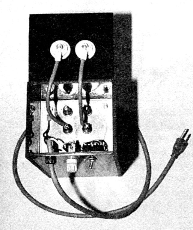
The high-voltage source should be placed in a well-insulated case or cabinet. If the case is metal, it should be adequately grounded. In the photograph in the opening of this article, a 7-kilovolt transformer was placed in a 1/4-inch Plexiglas case with the primary winding connected via fuse and switch to the 117-volt AC input. The output of the transformer was connected via high-voltage TV anode hook-up wire to two pieces of no. 12 copper wire used for the vee-shaped electrodes that protrude from porcelain insulators. When removing the insulation, be sure not to nick the wire. The connections between the transformer's secondary and the bottom of the insulators must be kept as short as possible and void of sharp bends (see Fig. 2). Exposed high-voltage points were given a coat of RTV silicon rubber to prevent any arcing inside the enclosure.
Adjustment and operation
The last step in getting your Jacob's Ladder to work is the adjustment of the vee electrodes. DO NOT MAKE ANY ADJUSTMENTS WHEN THE UNIT IS TURNED ON. The unit should be turned off and unplugged when making adjustments, to prevent accidental electrical shocks.
The electrodes must be close enough at the bottom to establish the spark or arc-over, with the wires gently angling away from one another to form the "V." The initial distance at the base to start the spark will vary with the voltage applied, humidity, altitude, etc.; so, it's pretty much done by trial and error. Start with the wires at the base about an inch apart when using 10 kilovolts or more, and move them closer in small increments until an arc is established. But remember to kill the power before each adjustment.
When the distance is correct, the arc should start. On the other hand, if the ladder arcs at the initial setting, move the wires apart until an arc is just sustained. Placing the wires too close together will ruin the transformer over time. When you have established the arc, if it does not move up between the two diverging wires, they must be adjusted in or out.
Better safe than sorry
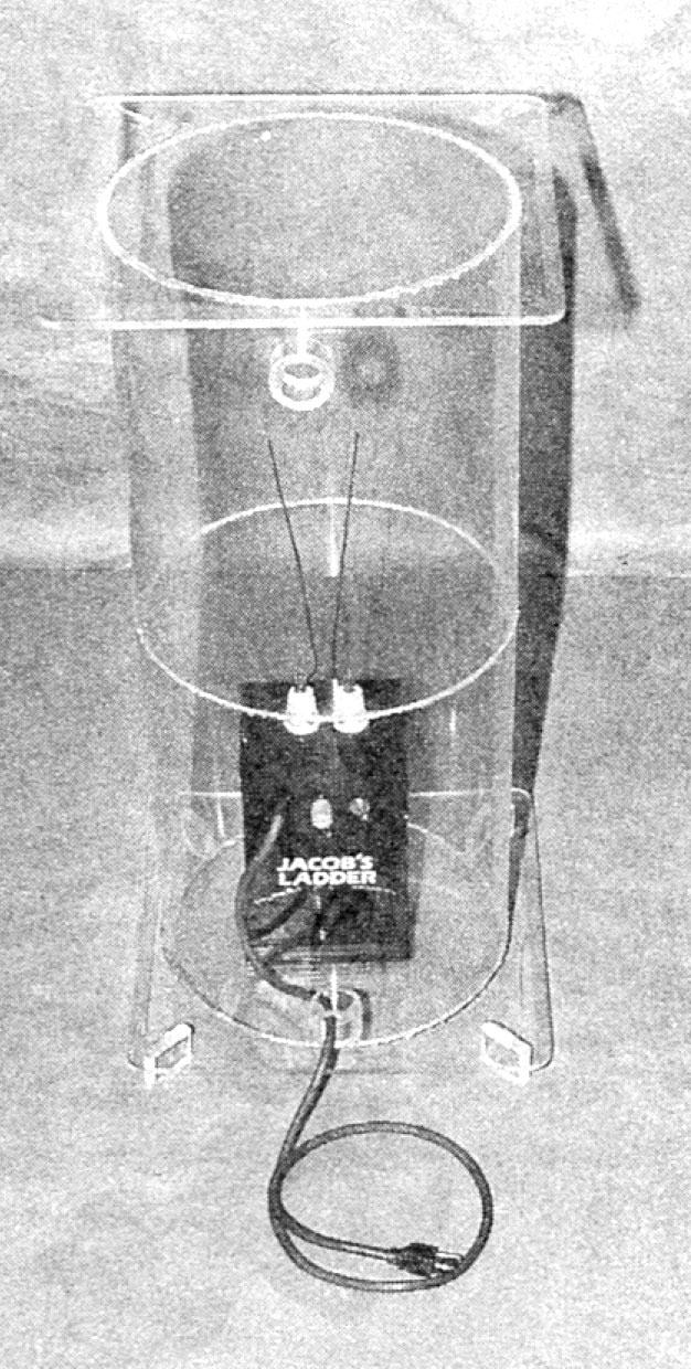
Once your Jacob's Ladder is up and running, a clear Plexiglas or acrylic cylinder around the entire unit will prevent the unthinkable from happening (see Fig. 3). The clear plastic housing should have vent holes at the top and bottom to allow heated gasses to escape, but not so large that the smallest child in the family can get his or her mitts or anything else inside. Generally, such cylinders can be purchased from most plastic-supply houses rather cheaply, and are well worth the added protection.
You do have to keep in mind that such high voltages are extremely dangerous, and you certainly don't want to come in contact with them.