
TCBA Volume 1 - Issue 1
Page 5 of 8
Tesla Coils Resurrected
High Voltage Experiments
by Lester Reukema
The entire outfit cost about fifteen dollars. Our power transformer is a 5-k.w. distribution transformer, with a ratio of transformation of 110 or 220 to 30,000 volts. We often work it up to 50,000 volts and 40 kilowatts for a few minutes at a time without serious overheating.
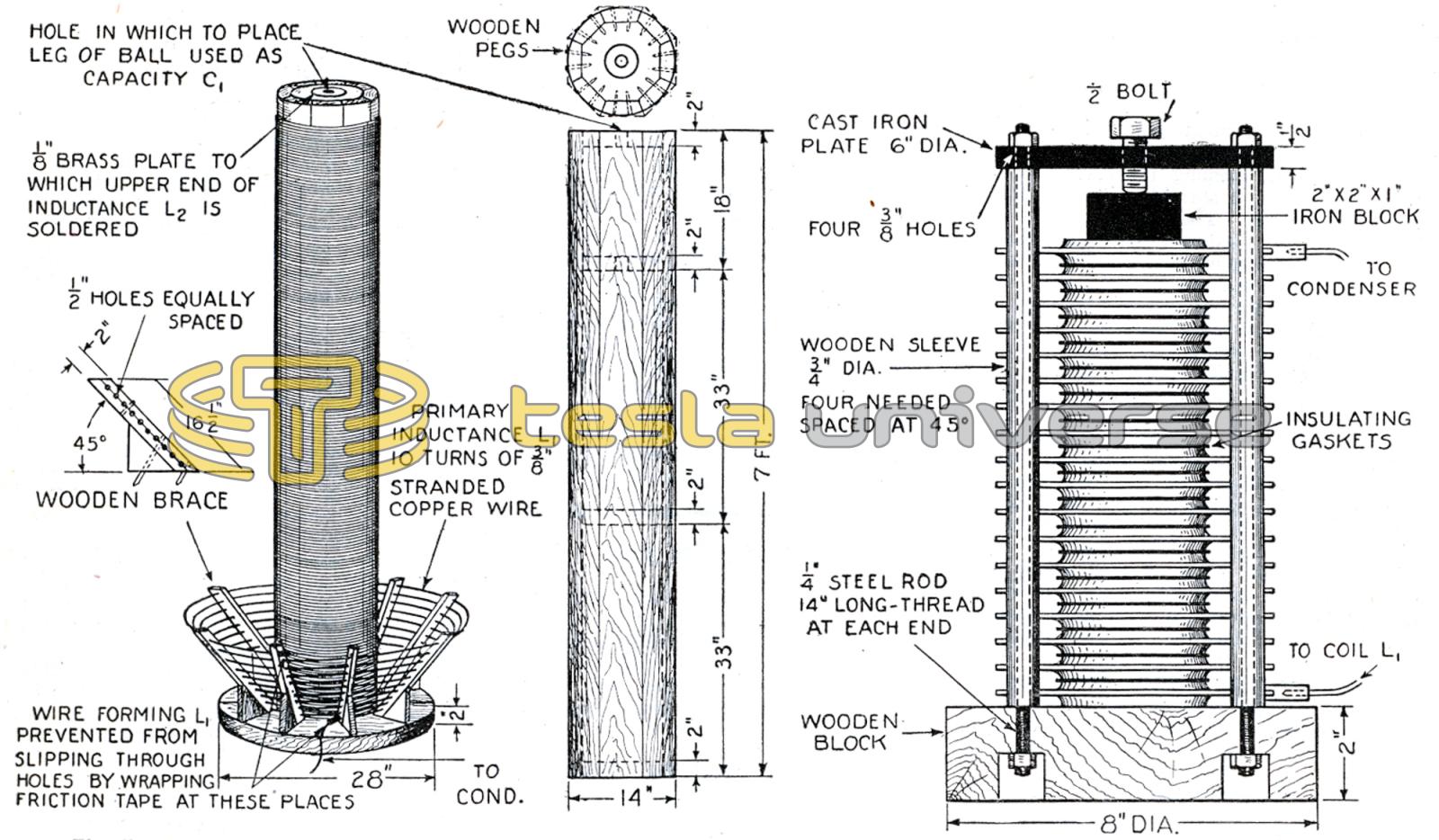
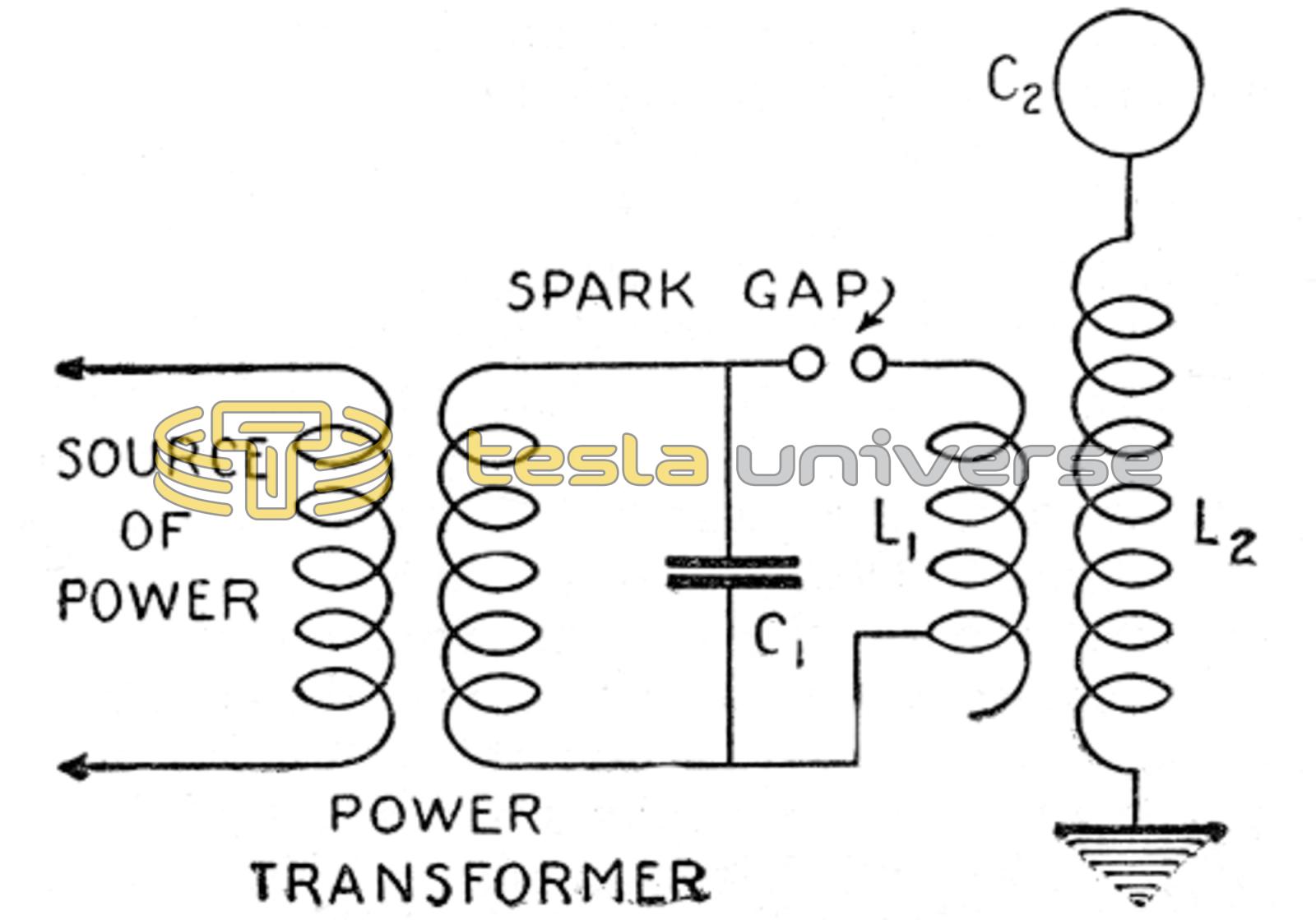
The source of power can be merely the ordinary 110-volt 60-cycle lighting circuit, although a 220-volt source will produce a more powerful display. In the diagram is presented the power transformer, which steps-up the voltage from 110 or 220 volts to 30,000 volts. Wires connect the high-voltage terminals of this transformer to the condenser (C1). From the condenser one wire goes to the spark-gap (S.G.) and the other to the coil of wire (L1), the connection merely clipping on to the coil, so that the number of turns of coil used can be readily changed. The other end of the coil is connected to the spark-gap, as shown. The coil (L1) is merely a few turns of heavy wire, wound in the form of the lower half of an inverted cone. Fig. 14 is included merely because it shows how this coil is made, and how the large coil (L2) is placed with respect to it. The large coil is seven feet long, 14 inches in diameter, and contains 750 turns of No. 22 copper wire, double-cotton covered. However, these dimensions are not essential.
Another coil, six feet long, a foot in diameter, with 1,000 turns, gave equally good results. The important thing to remember is to use no nails or other metal in its construction, as eddy currents set up in such metal by the high frequency power would soon set fire to the wood. The lower end of the winding on the large coil is connected to ground. A water pipe serves this purpose nicely. Do not use a gas pipe, as sparks may ignite the gas, if any is leaking out into the air. The upper end of the coil is connected to whatever is used as the secondary capacity (C2), a man in a sink full of water in this case, or a ball or various other terminals. The coils (L1) and (L2) together serve as a loosely coupled air-core transformer. The condenser (C1) consists merely of several pans of milk bottles filled half full of salt water, with salt water to the same height outside the bottles.
In a condenser, all that is necessary is two conducting elements separated by some non-conductor. In this case the salt water inside and outside the bottles forms the conducting surfaces, separated by the glass as the non-conductor. One high-voltage terminal of the power transformer is connected to the water outside of the bottles, the other to the water inside. To make this latter connection, we connected the transformer terminal to a piece of window screen placed on top of the bottles, then dropped short wires from the screen into the water in the bottles. In order to cut down corona loss in the condenser, a little oil was poured on top of the water. This, however, is not essential. The spark-gap used at first was a rotary gap, but later a quenched gap was used in its place, and gave better satisfaction. This consists of several disks of brass about six inches in diameter and an eighth of an inch thick, piled on top of each other with insulating gaskets 1/32 inch thick separating them from each other. The inner diameter of the gaskets was made about an inch less than the outer diameter. The whole pile was pressed firmly together to make the short gaps between disks air-tight.
The spark-gap is made just long enough to require the maximum value of voltage to discharge across it. As the spark passes the gap the air is ionized and thus made conducting, so that the resistance of the gap is decreased to an ohm or less, and the energy stored in the condenser surges across it. The discharge of a condenser, unless the resistance of the circuit is too great, is oscillatory, that is, the current surges back and forth until the resistance gradually uses up all of the energy. And just as a pendulum swings at a certain frequency, determined by the length of the pendulum, so the frequency of the surges to and from the condenser is determined by the capacity of the condenser and by the inductance of the circuit. The equation for the frequency of the oscillations is f1 = 1/2x3.1416 √ L1 C1, where f1 is frequency in cycles per second, L1 is inductance in henrys of coil L1, and C1 is the capacity in farads of the condenser (C1).