Nikola Tesla Patents
Nikola Tesla British Patent 186,083 - Improved Method of and Apparatus for the Economic Transformation of the Energy of Steam by Turbines
PATENT SPECIFICATION
186,083
Application Date: Mar. 24, 1921. No. 9099/21.
Complete Left: Sept. 5, 1921.
Complete Accepted: Sept. 25, 1922.
PROVISIONAL SPECIFICATION.
Improved Method of and Apparatus for the Economic Transformation of the Energy of Steam by Turbines.
I, Nikola Tesla, Mechanical and Electrical Engineer, citizen of the United States of America, of 8, West 40 Street, New York City, U.S.A., do hereby declare the nature of this invention to be as follows:-
The chief object of my improvements is to increase the efficiency of the existing steam power plants and thermo-dynamic transformers operated therefrom, but they may also be applied with like effect apart from the present establishments and are intended for the broad purpose of producing motive power, more economically, through the medium of steam.
It is well-known that notwithstanding the multiplication of hydro-electric and gas engine installations, steam is still the main source of power, but as a rule only a low fuel efficiency is secured owing to limitations inherent to the thermal process itself, as now carried out, and certain shortcomings of the present forms of apparatus. Furthermore, plans which have been heretofore contemplated for the attainment of better economy generally involved technical obstacles, more or less radical changes and necessarily considerable expense. For instance, in order to minimize the heat losses incident to the raising of steam, it has been suggested to burn the fuel together with air in the boiler and operate the engines by the mixture of steam and gas thus obtained. So far, however, attempts to effect combustion satisfactorily under such conditions have not been very successful. High pressures have been proposed with the same end in view but no great progress has yet been made in that direction; in fact many engineers view such projects with disfavor as they present a number of objectionable features and the possibilities of improvement are circumscribed. Again the employment of superheat as a means of increasing fuel efficiency is practicable only in a measure because the adopted types of prime movers do not lend themselves to high temperatures which, in conformity with the fundamental laws of thermodynamics, are indispensable to such a full realization.
These drawbacks have been successfully overcome in the method I have devised, which is very economical, readily applicable to the plants now in operation without appreciable modifications in them, and is rendered particularly advantageous through the instrumentality of a turbine or rotary engine described in my British Patent No. 24,001 of 1910 and improvements I have made in its construction since that time. This machine is capable of operating satisfactorily at very high temperatures, with cheap fuel, containing a large percentage of impurities, and without substantial impairment of efficiency as might be due to oxidation, roughening of the metal surfaces, or similar deteriorating actions which seriously interfere with the working of other heat engines now in use.
In applying my invention to a steam power plant I use air, under a pressure about equal to that of the boiler, for burning gas, crude oil, colloidal fuel or powdered coal in a chamber or conduit into which the steam is simultaneously admitted as cooling agent and diluent. The provisions to this end will greatly vary according to conditions. In central stations, factories, on shipboard and in many other places compressed air, as well as steam, is available and often, too, all the facilities for fuel storage and supply may be on hand. In such cases the benefits of my improvements will be readily derived with but little additional apparatus and at small cost. If the circumstances require, I provide an air-and also a gas compressor when necessary, driven directly from the shaft of the prime-mover or operated independently by electricity, steam or other motive agent. Generally these machines will be of the more efficient reciprocating type, but rotary compressors or both may be employed to secure some advantage. Irrespective of specific arrangements I effect the combustion while the fluids are in rapid motion and in a conduit preferably in close proximity to the engine, thus disposing of most of the difficulties previously encountered and at the same time materially reducing the radiation and conduction losses which would be incurred in the passage through long pipes. To better insure the maintenance of standard working conditions I may add to the equipment an equalizer of pressures operated differentially by the air and steam, but this device is not essential. The quantity of steam is so regulated that the highly heated mixture, upon expansion through the nozzle, attains an arbitrary temperature which the turbine can safely withstand. The elastic fluids, after traversing the rotor and giving up to the same a part of their kinetic energy, escape through the exhaust openings and serve the further purpose of preheating the feedwater, fuel, and likewise the air when desired. If intensely heated, the air and fuel will be conveyed to the combustion chamber separately, but in small installations it may be convenient to feed the fuel into the compressor or air pipe leading the carburated medium to the chamber. When simplicity is paramount, cheap coils or heaters for the combustibles and the feedwater will be resorted to, but in order to attain a still higher thermal efficiency I employ, besides, a small auxiliary boiler through which the exhaust is circulated. The steam thus obtained from waste heat is fed through a suitable valve, opening at the proper pressure, into the combustion space whence it passes, together with that furnished by the plant, through the turbine first doing useful work and then adding to the waste heat to be utilized in the manner set forth. More fuel may now be gradually admitted to maintain the normal temperature, this again increasing the heat in the exhaust and causing a more rapid generation of the steam, and so on, until finally a steady regime is established. However, if deemed of advantage under given operative conditions, the steam from the main boiler may be reduced in quantity in approximately the same measure as that from the auxiliary boiler is supplied.
This plan provides an efficient self-starting prime mover which may be operated as a steam - or mixed fluid turbine at will, without constructional change and is on this account very convenient. Minor departures from it, as may be dictated by the circumstances in each case, will obviously suggest themselves but if it is carried out on these general lines it will be found highly profitable to the owners of the steam plant while permitting the use of their old installation. However, the best economic results in the development of power from steam by my invention will be obtained in plants especially adapted for the purpose. It should be added that this method can also be successfully applied to condensing plants operating with high vacuum. In such a case, owing to the very great expansion ratio, the exhaust mixture will be at a relatively low temperature and suitable for admission to the condenser. Better fuel has to be used and special pumping facilities provided but the economic results attained will fully justify the increased outlay.
Dated this 24th day of March, 1921.
Nikola Tesla.
COMPLETE SPECIFICATION.
Improved Method of and Apparatus for the Economic Transformation of the Energy of Steam by Turbines.
I, Nikola Tesla, Electrical and Mechanical Engineer, citizen of the United States of America, of No. 8, West 40th Street, New York, N.Y., U.S.A., do hereby declare the nature of this invention and in what manner the same is to be performed, to be particularly described and ascertained in and by the following statement:-
The chief object of my improvements is to increase the efficiency of existing steam power plants and thermodynamic transformers operated therefrom, but they may also be applied with like effect apart from the present establishments and are intended for the broad purpose of producing motive power, more economically, through the medium of steam mixed with the heated products of combustion, while the apparatus is capable of actuation by steam alone. It is well-known that notwithstanding the multiplication of hydro-electric and gas engine installations, most of the motive power is still derived from this agent, but only a relatively low fuel efficiency is secured owing to limitations inherent to the thermal process itself, as now carried out, and certain shortcomings of the present forms of apparatus. These drawbacks have been largely overcome in the method I have devised, which is very economical, readily applicable to the plants now in operation without substantial modifications in them, and is rendered particularly advantageous through the instrumentality of a turbine or rotary engine described in my British Patent No. 24,001 of 1910 and improvements I have made in its construction since that time. This machine is capable of operating satisfactorily at very high temperatures, with cheap fuel containing a large percentage of impurities, and without material impairment of efficiency as might be due to oxidation, roughening of the metal surfaces or similar deteriorating actions which seriously interfere with the working of other heat engines.
In applying my invention to a steam power plant I use air, under a pressure about equal to that of the boiler, for burning gas, crude oil, colloidal fuel or powdered coal in a chamber or conduit, the products of combustion escaping from the same mixing with the steam on their way to the turbine being thus diluted and cooled to the desired temperature. The provisions to this end will greatly vary according to conditions. In central stations, factories, on shipboard and in many other places compressed air, as well as steam, is available and often, too, all the facilities for fuel storage and supply may be on hand. In such cases the benefits of my improvements will be readily derived with but little additional apparatus and at small cost. If the circumstances require, I provide an air - and sometimes also a gas-compressor driven either directly from the shaft of the primemover or independently by electricity, steam or other motive agent. Generally these machines will be of the more efficient reciprocating kind, but rotary compressors or composite types may be employed to secure some advantage. Irrespective of specific arrangements, I effect the combustion and mixing while the fluids are in rapid motion in a conduit which is, preferably, in close proximity to the turbine, thus disposing of most of the abovementioned difficulties previously encountered and at the same time considerably reducing the radiation and conduction losses which would be incurred in the passage through long pipes. To better insure the maintenance of standard working conditions, I may add to the equipment a device of the usual construction for equalizing the steam and air pressures. The quantity of steam is so regulated that the highly heated mixture, upon expansion through the nozzle, enters the turbine at a temperature which the machine can safely withstand. The elastic fluids, after traversing the rotor and giving up to the same a part of their kinetic energy, escape through the exhaust openings and may serve the further purpose of preheating the feedwater, fuel, and likewise the air when desired. If intensely preheated, the air and fuel will be conveyed to the combustion chamber or conduit separately, but in small installations it may be convenient to feed the fuel into the compressor or the air pipe thus bringing about a thorough mixture of the combustibles. When simplicity is of paramount importance, heaters may be resorted to for improving the economy, but in order to attain a still higher thermal efficiency I provide a boiler through which the working fluids, exhausted from the turbine, are circulated. The steam thus obtained from waste heat is fed through a suitable valve, into an inlet pipe whence it passes either separately or together with the mixed working fluid through the nozzle, first doing useful work and then adding to the waste heat of the exhaust. More fuel may now be gradually admitted to maintain in the inlet pipe the normal temperature, thus again increasing the heat in the exhaust and causing a more rapid generation of the steam, and so on, until finally a steady regime is established. However, if deemed of advantage under given operative conditions, the steam furnished by the plant may be reduced in quantity in approximately the same measure as that from the boiler is supplied.
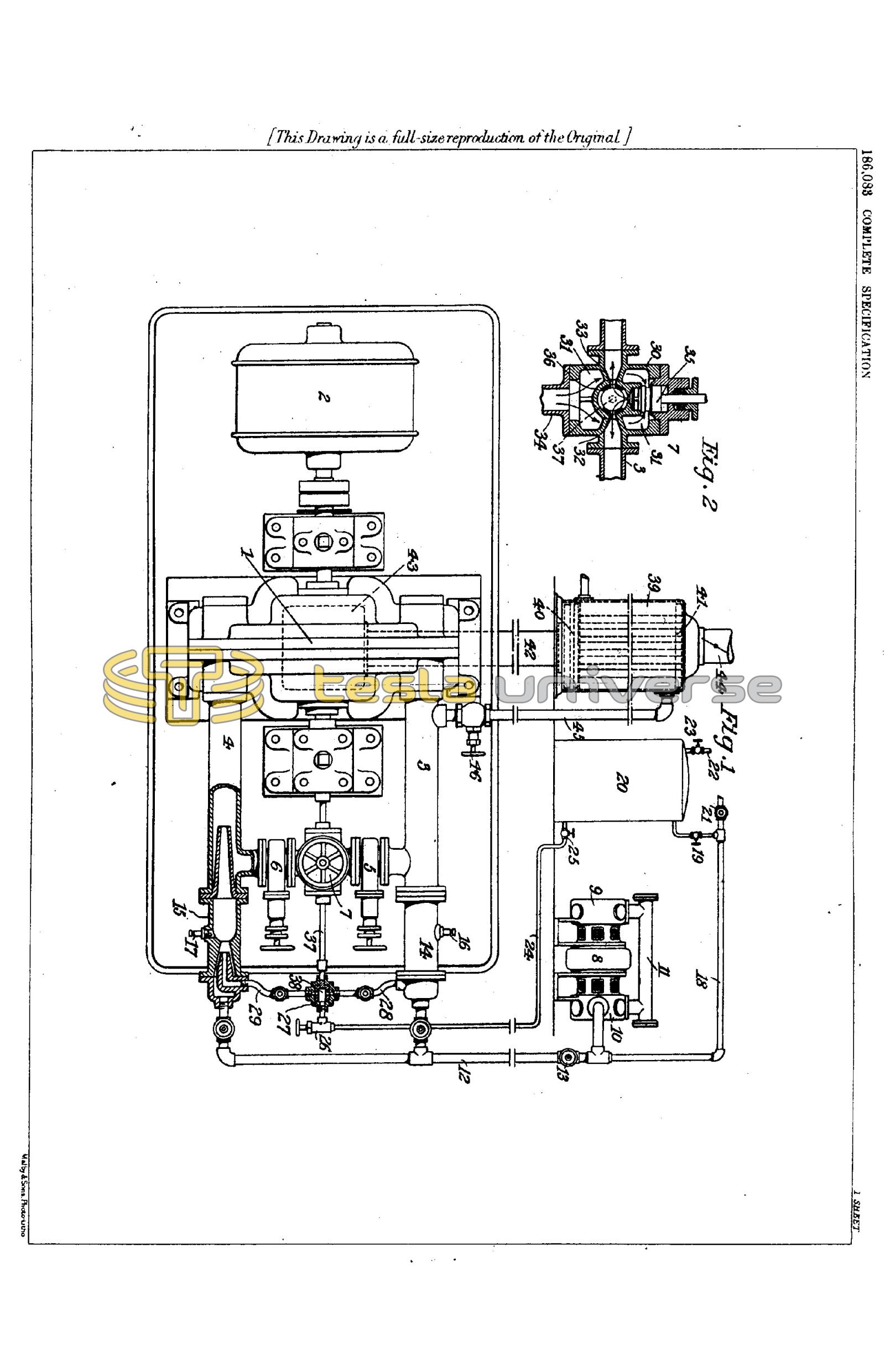
My invention will be more fully understood by reference to the accompanying drawings in which Figure 1 illustrates the general arrangement of the apparatus comprising the turbine, a compressor, a storage tank for the fuel, a boiler and the necessary pipe connections and controlling devices, and Figure 2 a vertical cross-section of the main valve for admission of the steam and regulation of its flow.
In the first named figure, 1 represents my turbine with its shaft flexibly coupled to a machine performing useful work, as dynamo 2. The general construction of the turbine is preferably as described in my British Patent No. 24,001 of 1910, two nozzles being provided, which are intended to operate in the same direction. The nozzles are contained in two diametrically opposite enlargements of the casing and communicate with inlet pipes 3 and 4 which are joined, through suitable valves 5 and 6, to the main steam admission and control valve 7, shown in section Figure 2 and to be described in detail.
The air compressor can be of any kind but is shown of the reciprocating high speed type, driven by an electric motor 8, and comprising two stages 9 and 10, with an intercooler 11. A pipe 12 carrying valve 13, connects the discharge duct of the compressor to flanged conduits 14 and 15 which are bolted to the inlet pipes 3 and 4 as indicated and equipped with means for ignition, as spark plugs 16 and 17. An extension 18 of pipe 12 leads through a valve 19, to the top of the fuel tank 20 and serves the purpose of maintaining in the latter the required pressure. When the employment of an air reservoir is deemed preferable extension 18 will be put in communication with the same through valve 21. A filling pipe 22, armed with valve 23, is attached to the top of tank 20 while near to its bottom is joined a discharge pipe 24 provided with valve 25 leading through a needle valve 26 to an automatic control valve 27 which is connected by pipes 28 and 29 to the flanged conduits 14 and 15.
The main valve 7 is designed for control of the steam flow both by automatic means and independently of the same. Its construction is clearly indicated in Figure 2, representing a vertical cross-section. The device consists of a casting 30 with inlet ports 31 and outlets 32 and 33, which are joined by flanges to pipes 3 and 4. The open bottom of the casting is connected to a steam inlet pipe 34 while the top carries a throttle valve 35 for turning on and shutting off the steam. Below the seat of this valve the casting has a transversal bore, into which is freely fitted a hollow cylinder 36 with balanced intake and exhaust openings, the latter registering with outlets 32 and 33 in the casting. The cylinder 36 is rigidly joined through a rod 37 with a hollow plunger 38 (Fig. 1) having diametrically opposite ports matching those in the stationary part of valve 27.
The boiler 39, which may be of the vertical tubular type as illustrated, is connected through its headers 40 and 41 on the lower end to main 42 communicating with the exhaust opening 43 of the turbine, and on the upper one to discharge conduit 44 through which the hot fluids, after traversing the boiler tubes, escape into the atmosphere or are led to an economizer for preheating the feed-water or otherwise utilizing the waste heat. A conduit 45 joins the top of the boiler to inlet pipe 3 through a suitable valve 46 which may be operated either by hand or automatically.
From the foregoing the operation will now be readily understood. At the start valve 46 being closed and 5 and 6 open, steam from the plant is admitted through throttle and control valve 7 whence it passes into the inlet pipes 3 and 4 and communicating nozzles from which it issues at high velocity setting the rotor in motion, the machine operating purely as a steam turbine. The spark plugs 16 and 17 are then brought into play and valves 13, 19 and 25 opened, the latter allowing the fuel to flow from the tank, chiefly under the action of gravity, to needle valve 26 which is gradually turned on. The fuel thereupon passes through the ports of hollow plunger 38 and pipes 28 and 29 into apparatus for mixing and combustion, the construction of which is clearly shown in the cross-section at the lower branch, it being understood that the arrangement on the upper branch is identical. As will be seen the conduit 15 is armed on one end with a spraying device and on the other with a funnel-shaped extension which is held tight between flanges and projects far into the steam inlet pipe 4. The fuel, atomized by the inrushing air, enters the combustion chamber formed by an enlargement in conduit 15, and is then ignited in the same, the products of combustion escaping into the inlet pipe 4 and mixing with the steam on their way to the nozzle. This kind of apparatus overcomes the difficulty heretofore encountered in attempts to effect combustion practically and will work satisfactorily even if there are considerable fluctuations in the steam and air pressures, as the faster moving fluid aspirates the slower one. It has been assumed that liquid fuel is used but powdered coal may also be employed in substantially the same manner with slight constructive modifications, the powder being conveyed to the combustion chamber either independently of, or with, the air. The quantity of the combustibles is so regulated by manipulation of valves 13 and 26 (and also 5, 6 and throttle 7, if suitable) that the mixture, escaping from the nozzles, will be at a temperature considered safe for the operation of the turbine. To facilitate this any of the well-known compound valves may be provided for the purpose of admitting the combustibles always in the required proportions irrespective of their total quantity.
When the steam in boiler 39, raised by the exhaust mixture passing through the tubes, attains the required pressure, it is admitted through valve 46, conduit 3 and corresponding nozzle, to the rotor, adding kinetic energy to the same. Feed-water, preferably heated by the turbine exhaust, is supplied to the boiler in the same measure as steam is drawn off, any ordinary means to this end being employed.
The automatic control of the flow of steam and fuel may be effected by any kind of speed governor operatively connected to rod 37 so that the supply is reduced as the speed increases. In addition to the means shown, an air valve may be provided, actuated automatically by the governor either through rod 37 or otherwise. For further convenience and to enable the independent control of the air and fuel supply in the two branches, conduits 14, 15 and pipes 28, 29 may be equipped with valves, indicated in Fig. 1, the numbering of which is deemed unnecessary.
The amount of power obtainable from boiler 39 will vary according to conditions. Turbines as described in my said prior specification are capable of operating at a very high exhaust temperature and then the energy recovered from the waste heat in this manner may be a large fraction of the whole useful work. In such as case conduit 3, pipes 14 and 28 together with all their adjuncts, as illustrated, can be omitted and the steam supplied directly to the nozzle through valve 46. Or these connections and adjuncts may be left undisturbed and a separate nozzle provided. In admitting the steam from the boiler to the turbine rotor through independent channels, the practical advantage is secured that the pressure may vary considerably without detracting much from the efficiency of the machine, which will be improved through preheating of the combustibles by any of the well-known means.
This plan provides an efficient self-starting mixed-fluid turbine which may also be operated with steam alone, merely by shutting off the air and fuel supply, and is on this account very convenient. Minor departures from it, as may be dictated by the circumstances, will obviously suggest themselves, but if it is carried out on these general lines it will be found highly profitable to the owners of the steam plant while permitting the use of their old installation. However, the best economic results in the development of power from steam by my invention will be obtained in plants especially adapted for the purpose. It should be added that this method can also be successfully applied to condensing plants operating with high vacuum. The production and maintenance of the latter will be materially facilitated by the employment of a pump as shown in my British patent before referred to. In such instances, owing to the very great expansion ratio, the exhaust mixture will be at a relatively low temperature and suitable for admission to the condenser. This will call for better fuel and special pumping facilities, but the economic results attained will fully justify the increased outlay.
Having now particularly described and ascertained the nature of my said invention and in what manner the same is to be performed, I declare that what I claim is:-
- In a turbine installation normally working with a mixture of steam and products of combustion and in which the exhaust heat is used to provide steam which is supplied to the turbine, providing a valve governing the supply of such last mentioned steam so that the pressures and temperatures can be adjusted to the optimum conditions of working.
- A turbine installation as described and claimed in Claim 1 so arranged that it is capable of starting with steam alone.
- A turbine installation as described and claimed in Claim 1 or 2 in which the turbine is of the friction disc type adapted to work with fluids at a very high temperature such as is described in Specification 24,001 of 1910.
- The combined apparatus substantially as described and shown in the drawings.
Dated the 23rd day of August, 1921.
Nikola Tesla.