Nikola Tesla Patents
Nikola Tesla U.S. Patent 1,655,114 - Apparatus for Aerial Transportation
| Patented Jan. 3, 1928. | 1,655,114 |
NIKOLA TESLA, OF NEW YORK, N. Y.
APPARATUS FOR AERIAL TRANSPORTATION.
Application filed October 4, 1927. Serial No. 223,915.
This application is a continuation in part of my application Serial No. 499,518, filed September 9, 1921, and is made pursuant to the rules of the Patent Office, its purpose being to describe and claim apparatus which I have invented for carrying into practice the method therein disclosed.
The invention consists of a new type of flying machine, designated “helicopter-plane”, which may be raised and lowered vertically and driven horizontally by the same propelling devices and comprises: a prime mover of improved design and an airscrew, both especially adapted for the purpose, means for tilting the machine in the air, arrangements for controlling its operation in any position, a novel landing gear and other constructive details, all of which will be hereinafter fully described.
The utility of the aeroplane as a means of transport is materially lessened and its commercial introduction greatly hampered owing to the inherent inability of the mechanism to readily rise and alight, which is an unavoidable consequence of the fact that the required lifting force can only be produced by a more or less rapid translatory movement of the planes or foils. This indispensable high velocity, imperiling life and property, makes it necessary to equip the machine with special appliances and provide suitable facilities at the terminals of the route, all of which entail numerous drawbacks and difficulties of a serious nature.
More recently, professional attention has been turned to the helicopter which is devoid of planes as distinct organs of support and, presumably, enables both vertical and horizontal propulsion to be satisfactorily accomplished through the instrumentality of the propeller alone.
The prospects of such a flying machine appear at first attractive, primarily because it makes possible the carrying of great weight with a relatively small expenditure of energy. This follows directly from the fundamental laws of fluid propulsion, laid down by W. T. M. Rankine more than fifty years ago, in conformity with which the thrust is equal to the integral sum of the products of the masses and velocities of the projected air particles; symbolically expressed,
T = Σ(mv).
On the other hand, the kinetic energy of the air set in motion is
E = Σ(lmv2/2).
From these equations it is evident that a great thrust can be obtained with a comparatively small amount of power simply by increasing the aggregate mass of the particles and reducing their velocities. But the seemingly great gain thus secured is of small value in aviation for the reason that a high speed of travel is generally an essential requirement which cannot be fulfilled except by propelling the air at high velocity, and that obviously implies a relatively small thrust.
Another quality commonly attributed to the helicopter is great stability, this being apparently a logical inference judging from the location of the centers of gravity and pressure. It will be found, though, that contrary to this prevailing opinion the device, while moving in any direction other than up or down, has an equilibrium easily so disturbed and has, moreover, a pronounced tendency to oscillate.
In explanation of these and other peculiarities, assume the helicopter poised in still air at a certain height, the axial thrust T just equaling the weight, and let the axis of the propeller be inclined to form an angle a with the horizontal. The change to the new position will have a two-fold effect: the vertical thrust will be diminished to
Tv = T sina.
and at the same time there will be produced a horizontal thrust
Th = T cosa.
Under the action of the unbalanced force of gravity, the machine will now fall along a curve to a level below and if the inclination of the propeller as well as its speed of rotation remain unaltered during the descent, the forces T, Tv, and Th will continuously increase in proportion to the density of the air until the vertical component Tv of the axial thrust T becomes equal to the gravitational attraction. The extent of the drop will be governed by the inclination of the propeller axis and for a given angle it will be, theoretically, the same no matter at what altitude the events take place. To get an idea of its magnitude suppose the elevations of the upper and lower strata measured from sea level be h1 and h2, respectively, d1 and d2 the corresponding air densities and H = 26,700 feet the height of the “uniform atmosphere,” then as a consequence of Boyle's Law the relation will exist
h1-h2 = H log d2/d1
It is obvious that
T/Tv = T/T sin a = 1/sina must be equal to d2/d1
in order that the vertical component of the axial thrust in the lower stratum should just support the weight. Hence
H1-h2 = H log 1/sin a
Taking, in a special case, the angle a = 60 degrees, then
1/sin a = 1/0.866 = 1.1547, and
h1-h2 - 26,700xlog 1.1547=3,840 feet.
In reality the drop will be much greater for the machine, upon reaching the lower layer with a high velocity relative to the medium, will be urged further down along the curved path and the kinetic energy, in the vertical sense, possessed by the moving mass must be annihilated before the fall is arrested in a still denser air stratum. At this point the upward thrust will be far in excess of the opposed pull of the weight and the apparatus will rise with first increasing and then diminishing speed to a height which may approximate the original. From there it will again fall and so on, these operations being repeated during the forward flight, the up and down excursions from the main horizontal line gradually diminishing in magnitude. After a lapse of time, determined by numerous influences, these deviations should become insignificant and the path described nearly rectilinear. But this is next to impossible as can be readily shown by pointing out another curious feature of the helicopter.
In the foregoing the axis of the propeller was supposed to move always parallel to itself, which result might be accomplished by the use of an adjustable aileron. In this connection it may be pointed out, however, that such a device will not act in the manner of a rudder, coming into full play at intervals only and performing its functions economically, but will steadily absorb energy, this occasioning a considerable waste of motive power and adding another to the many disadvantages of the helicopter.
Let now the machine be possessed of a certain degree of freedom, as will be the case normally, and observe in the first place that the blades of the propeller themselves constitute planes developing a reaction thrust, the pressure on the lower leading blade being greater than that exerted on the higher one owing to the compression of the air by the body of the machine and increased density in that region. This thrust tending to diminish the angle a, will vary during one revolution, being maximum in a position when the line of symmetry of the two propeller blades and that of flight are in the same vertical plane and minimum when the former is at right angles to it. Nevertheless, if the horizontal speed is great, it may be considerable and sufficient to quickly overcome the inertia and gyroscopic resistances all the more readily as the upper blade operates to the same effect. Moreover, this intermittent action partakes of the regenerative quality, the force increasing as the angle diminishes up to a maximum for a = 45 degrees, and may also give rise to disturbing resonant vibrations in the structure. As its axis is tilted more and more, the vertical sustaining effort of the propeller correspondingly diminishes and the machine will fall with a rapidly increasing velocity, which may finally exceed the horizontal, when the reaction of the blades is directed upward so as to increase the angle a and thereby cause the machine to soar higher. Thus periodic oscillations, accompanied by ascents and descents, will be set up which may well be magnified to an extent such as to bring about a complete overturn and plunge to earth.
It is held by some experts that the helicopter, because of its smaller body resistance, would be capable of a higher speed than the aeroplane. This is an erroneous conclusion, contrary to the laws of propulsion. It must be borne in mind that in the former type, the motive power being the same, a greater mass of air must be set in motion with a velocity smaller than in the latter, consequently it must be inferior in speed. But even if the air were propelled in the direction of the axis of the screw with the same speed V in both of them, while the aeroplane approximates the same, the helicopter can never exceed the horizontal component V cos a which, under the theoretically most economical conditions of operation, would only be 0.7V, and this would be true no matter how much its resistance is reduced.
Another very serious defect of this kind of flying machine, from the practical point of view, is found in its inability of supporting itself in the air in case of failure of the motor, the projected area of the propeller blades being inadequate for reducing the speed of the fall sufficiently to avoid disaster, and this is an almost fatal impediment to its commercial use.
From the preceding facts, which are ignored in the technical publications on the subject, it will be clear that the successful solution of the problem is in a different direction.
In an application of even date, referred to above, I have disclosed an invention which meets the present necessity in a simple manner and, briefly stated, consists in a novel method of transporting bodies through the air according to which the machine is raised and lowered solely by the propeller and sustained in lateral flight by planes.
My present application is based on new and useful features and combinations of apparatus which I have devised for carrying this method into practice.
Full knowledge of these improvements will be readily gained by reference to the accompanying drawings in which
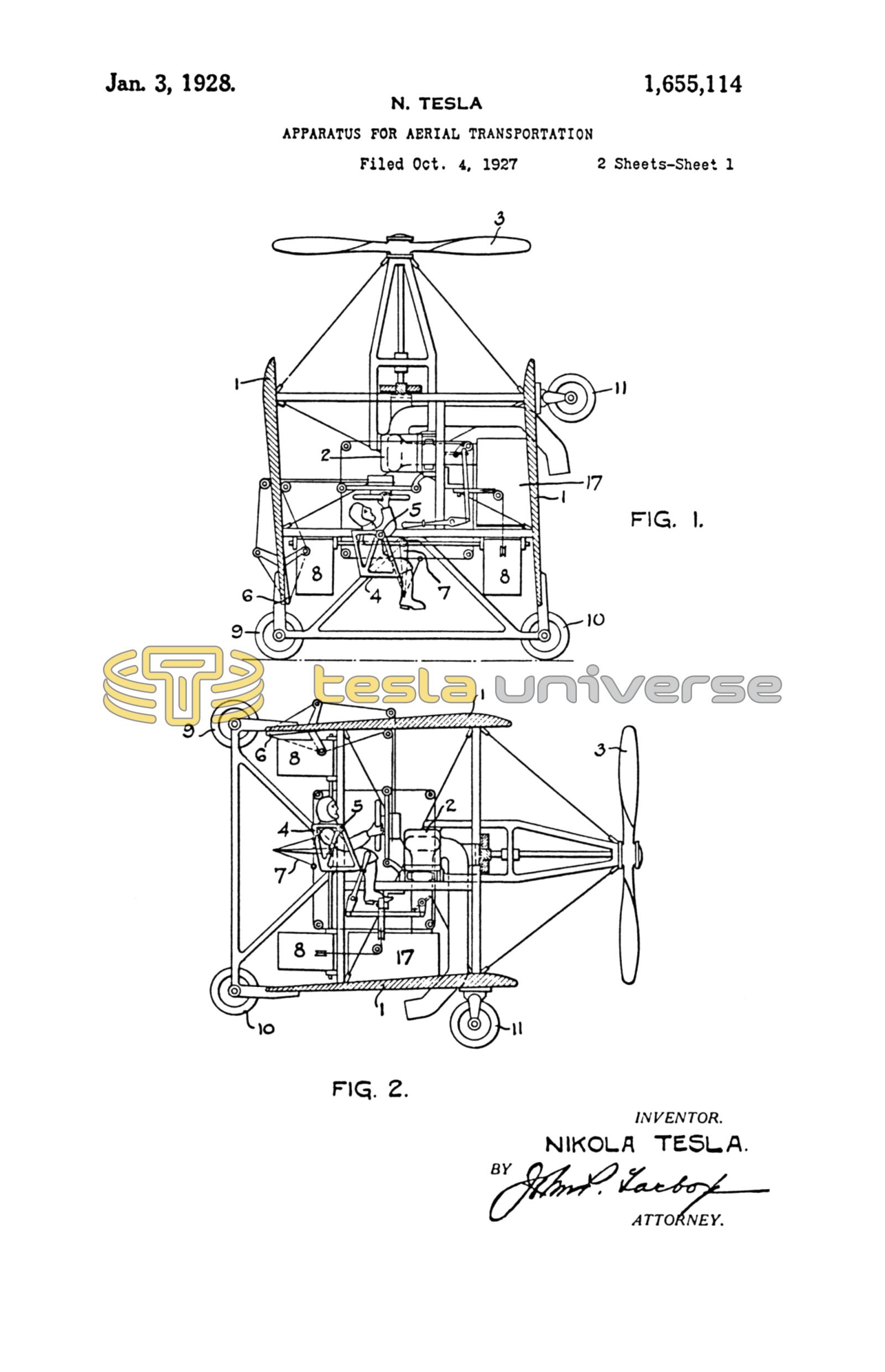
Fig. 1 illustrates the machine in the starting or landing position and
Fig. 2 in horizontal flight;
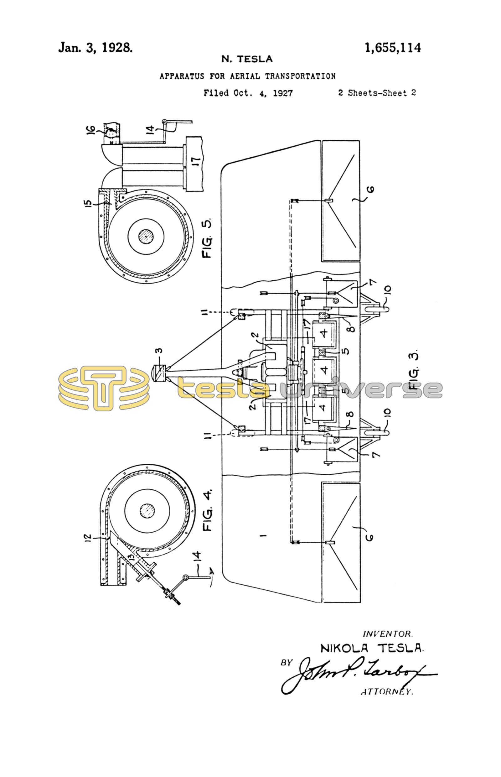
Fig. 3 is a plan view of the same with the upper plane partly broken away and
Fig. 4 and Fig. 5 sectional views of constructive details.
The structure is composed of two planes or foils 1, 1 rigidly joined. Their length and distance apart may be such as to form a near-square for the sake of smallness and compactness. With the same object the tail is omitted or, if used, it is retractable. In order to raise the machine vertically a very light and powerful prime mover is necessary and as particularly suited for the purpose, I employ, preferably, a turbine described in my U. S. Patent 1,061,206 of May 6, 1913, which not only fulfills these requirements but lends itself especially to operation at very high temperatures. Two such turbines, designated 2, 2 together with other parts and accessories of the power plant, are bolted to the frame, being placed with due regard to the centers of gravity and pressure. The usual controlling means are provided and, in addition to these, any of the known stabilizing devices may be embodied in the machine. At rest the planes are vertical, or nearly so, and likewise the shaft driving the propeller 3, which is of a strength, size and pitch such as will enable it to lift the entire weight vertically and withstand safely the stresses. Power is transmitted to the shaft from the turbines through gearing which may be of the single reduction type as illustrated, the turbines rotating in the same direction and neutralizing the gyroscopic moment of the screw. If, instead of one, two propellers are used, either coaxially or otherwise disposed, the motors should revolve in opposite directions. The seats 4, 4, 4 for the operator and passengers are suspended on trunnions 5, 5 on which they can turn through an angle of about 90 degrees, springs and cushions (not shown) being employed to insure and limit their motion through this angle. The ordinary devices for lateral and directional control 6, 6, 7, 7 and 8, 8 are provided with mechanical connections enabling the aviator to actuate them by hand or foot from his seat in any position.
Stated in a few words, the operation is as follows: At the start, sufficient power is turned on by suitable means, also within reach, and the machine rises vertically in the air to the desired height when it is gradually tilted through manipulation of the elevator devices and then proceeds more and more like an aeroplane, the sustaining force of the propeller being replaced by vertical reaction of the foils as the angle of inclination diminishes and horizontal velocity increases. In descending, the forward speed is reduced and the machine righted again, acting as a helicopter with the propeller supporting all the load. The turbine used is of great lightness and activity exceptionally qualified to perform such work for which the present aviation motors are unsuited. It is capable of carrying an extraordinarily great overload and running at excessive speed, and during the starting, landing and other relatively short operations, not only can the necessary power be easily developed, but this can be accomplished without incurring a serious loss of efficiency. Owing to its extreme simplicity the motive apparatus is very reliable, but should the power give out accidentally, landing can still be effected by volplaning. For this purpose, in addition to wheels 9, 9 and 10, 10, wheels 11, 11 are employed, the latter being mounted on the forward end under the lower plane and so that when the machine rests on level around, the propeller shaft will have the desired inclination which is deemed best for rising in the manner of an aeroplane. Such a “helicopter-plane,” constructed and operated as described, unites the advantages of both types and seems to meet well the requirements of a small, compact, very speedy and safe craft for commercial use.
The abnormal power requirements are met by supplying more of the working fluid to the motors and driving them faster, or running them at about the same speed and increasing the thrust by adjustment of the pitch of the propeller. On account of simplicity and much greater range it is preferable to resort to the first method, in which case the screw should be designed to work most economically in horizontal flight, as its efficiency in the starting and landing operation is of comparatively small importance. Instead of a single large propeller, as described, a number of small ones can be used, when the turbine units may be connected advantageously in stages and the gearing dispensed with. The biplane seems to be particularly well suited for the chief purpose contemplated, but the invention is equally well applicable to monoplanes and other types.
In order to secure the best results I have found it indispensable to depart, in some respects, from the usual design of my turbines and embody in them certain constructive features and means for varying the power developed from the minimum necessary in horizontal flight to an amount exceeding by far their rated performance, as may be required in the operations of ascent and descent, or spurts of speed, or in combating the fury of the elements. Furthermore, I so proportion and coordinate the fluid pressure generator supplying the primary energy, the propelling and the controlling means, that for any attitude or working condition of the machine the requisite thrust may be almost instantly produced and accurately adjusted.
The understanding of these improvements will be facilitated by reference to Fig. 4 and Fig. 5. In the first named the turbines are intended to operate as rotary engines, expanding the gases in the rotor as well as the inlet nozzle or port 12, the depth of which can be varied by shifting a block 13, fitting freely in a milled channel of the casing, through the medium of lever 14 controlled by the aviator. The orifice for the passage of the elastic fluid is straight or slightly converging, so that a much smaller velocity is obtained than with an expanding nozzle, this enabling the best relation between the peripheral speed of the rotor and that of the fluid to be readily attained. The performance of such an engine at constant pressure of supply is, within wide limits, proportionate to the quantity of the working medium passed through the inlet port and it is practicable to carry, for indefinite intervals of time, an exceedingly great overload, by which I mean up to three or even four times the normal. Exceptional strength and ruggedness of the motors being imperative in view of centrifugal stresses and critical speed, their weight need not be appreciably increased as would be the case in other forms of prime movers in which, as a rule, the weight is in nearly direct proportion to the power developed. To accomplish my purpose I further provide commensurately larger inlet and outlet openings. No serious disadvantage is thereby incurred because windage and other losses are virtually absent and most of the rotary effort is due to the peripheral parts of the discs. As shown in the figure, block 13 is in the position corresponding to minimum effort, the section of the inlet channel being about one-fifth of the whole which is obtained when the block is pulled in its extreme position indicated by the dotted line. Owing to the increase of the coefficient of contraction and counterpressure attendant the enlargement of the inlet, the same should be made of ample section.
Figure 5 shows a different means for attaining the same purpose. In this case the motors operate like true turbines, the working fluid being fully expanded, or nearly so, through divergent exchangeable nozzles as 15, having a throat of sufficient section for the passage of fluid required during maximum performance. The exhaust opening is also correspondingly enlarged, though not necessarily to the extent indicated in Figure 4. The power is varied by means of a throttle valve 16, as used in automobiles, located in the conduit supplying the air and carbureted fuel to the fluid pressure generator and mechanically connected to the controlling lever 14. This apparatus is of a capacity adequate to the maximum demand by which I do not mean that it is necessarily much larger than required for normal performances, but is merely designed to supply the working fluid or, broadly stated, energy—whenever desired, at a rate greatly exceeding the normal. In Figure 3 this apparatus is diagrammatically indicated by 17, and may be any one of a number of well-known types, producing pressure by internal combustion of a suitable fuel or by external firing of a steam boiler. In the latter case, with constant pressure, the arrangement shown in Figure 4 is best to employ, while the plan illustrated in Figure 5 can be used to advantage when both pressure and quantity of fluid are varied.
In operation for vertical ascent, the machine being in the attitude of Figure 1, the aviator will push forward lever 14 and supply sufficient primary energy to the motors for lifting the machine with the desired velocity. When the objective elevation is reached rudders 7, 7 are manipulated to incline the machine at a certain angle, the aviator simultaneously applying more pressure to the lever and augmenting the fluid supply to the motors, thereby increasing the propeller thrust in the vertical direction so as to prevent the machine from descending. He continues these operations always coordinating the thrust developed with the changes in attitude of the machine until a certain angle of inclination is attained and the machine is supported chiefly by reaction of the planes. At this stage he begins to reduce the pressure on the lever and supply of working fluid simultaneously decreasing the angle of inclination thus finally effecting, by insensible steps, horizontal flight.
It should be understood that descent and alighting, as well as rising in the manner of a true aeroplane may be accomplished as usual. In such case the motors will be operated at their normal rated capacity. However, when excessive speed becomes necessary, the effort of the motors may be instantly and greatly augmented by merely manipulating block 13 or valve 16 as described.
Whenever it is desired to descend vertically, the aviator will reverse the operations as applying to substantial vertical ascent, which is to say, bring the machine gradually into starting attitude, at the same time increasing the supply of fluid to the motors and the vertical component of the propeller thrust, while reducing the horizontal. Finally, he will steadily reduce the fluid supply and the vertical thrust so as to descend to the landing place at a very low, safe velocity.
In the preceding I have described a flying machine characterized by a number of novel constructive and operative features and well suited for meeting a pressing necessity in the present state of the art. The chief improvements consist in first, adapting my turbine motor for excessive overload without appreciable increase of its weight, second, providing large variable inlet ports and corresponding exhaust openings, with the object of meeting the abnormal power requirements in the starting, landing and other short operations, and still preserving a high efficiency in horizontal flight; third, combining with the turbine a fluid pressure generator of adequate capacity with means for control and, fourth, embodying these and other features in a suitable structure improved in various details. These may be greatly varied and I wish it to be understood that I do not limit myself to the precise arrangements illustrated and described.
I claim as my invention:
1. In an aeroplane adapted for vertical and horizontal propulsion and change from one to the other attitude, the combination of means for tilting the machine in the air, a fluid pressure generator of a capacity several times greater than normally required in horizontal flight, a motor capable of carrying overloads adequate for support in all attitudes, and means for controlling the supply of the fluid to the motor in accordance with the inclination of the machine.
2. In an aeroplane adapted for vertical and horizontal propulsion and change from one to the other attitude, the combination with means for tilting the machine in the air and a system producing thrust approximately parallel to the principal axis of the same and including a fluid pressure generator having a capacity several times greater than normally required in horizontal flight, a motor capable of carrying over-loads adequate for support in all altitudes, and means for controlling the supply of the fluid to the motor in accordance with the inclination of the machine.
3. In an aeroplane adapted for vertical and horizontal propulsion and change from one to the other attitude, the combination of means for tilting the machine in the air, a fluid pressure generator capable of supplying fluid at a rate several times greater than required for horizontal flight, a prime mover consisting of a rotor of plane spaced discs with central openings and an enclosing casing with inlet and outlet orifices of a section much greater than required for normal performances respectively at the periphery and center of the same, and means for controlling the supply of the fluid to the motor in accordance with the inclination of the machine.
4. In an aeroplane adapted for vertical and horizontal propulsion and change from one to the other attitude, the combination of means for tilting the machine in the air, a thrust producing system having its principal energy producing elements designed for normal load in horizontal flight but capable of carrying over-loads adequate for support of the aeroplane in all attitudes, and means for controlling the energy produced in said system in accordance with the inclination of the machine.
5. In a flying machine of the kind described in combination with means for vertical and lateral control of two wheel bases at right angles to one another as set forth.
6. In a flying machine of the kind described in combination with means for vertical and lateral control of two wheel bases at right angles to one another and having one or more wheels common to both.
In testimony whereof I hereunto affix my signature.
NIKOLA TESLA.