Nikola Tesla Patents
Nikola Tesla U.S. Patent 382,845 - Commutator for Dynamo-Electric Machines
NIKOLA TESLA, OF NEW YORK, N.Y., ASSIGNOR OF ONE-HALF TO CHARLES F. PECK, OF ENGLEWOOD, NEW JERSEY.
COMMUTATOR FOR DYNAMO-ELECTRIC MACHINES.
SPECIFICATION forming part of Letters Patent No. 382,845, dated May 15, 1888.
Application filed April 30, 1887. Serial No. 236,711. (No model.)
To all whom it may concern:
Be it known that I, NIKOLA TESLA, from Smiljan, Lika, border country of Austria-Hungary, at present residing in this city, county, and State of New York, have invented certain new and useful Improvement in Commutators for Dynamo-Electric Machines and Motors, of which the following is a specification, reference being had to the drawings accompanying and forming a part of the same.
The invention relates to dynamo-electric machines or motors, and is an improvement in the devices for commutating and collecting the currents.
The objects of the invention are, first, to avoid the sparking and the gradual wearing away or destruction of the commutator-segments and brushes or collectors resulting therefrom; second, to obviate the necessity of readjustment of the commutator or the brushes or collectors and other consequences of the wear of the same; third, to render practicable the construction of very large dynamo-electric machines and motors with the minimum number of commutator-segments, and fourth, to increase the efficiency and safety and reduce the cost of the machine.
In carrying out my invention in a manner to accomplish these results I construct a commutator and the collectors therefore in two parts mutually adapted to one another, and, so far as the essential features are concerned, alike in mechanical structure. Selecting as an illustration a commutator of two segments adapted for use with an armature the coils or coil of which have but two free ends, connected respectively to the said segment, the bearing-surface is the face of a disk, and is formed of two metallic quadrant-segments and two insulating-segments of the same dimensions, and the face of the disk should be smoothed off, so that the metal and insulating segments are flush. The part which takes the place of the usual brushes, or what I term the "collector," is a disk of the same character as the commutator and having a surface similarly formed with two insulating and two metallic segments. These two parts are mounted with their faces in contact and in such manner that the rotation of the armature causes the commutator to turn upon the collector, whereby the currents induced in the coils are taken off by the collector-segments and thence conveyed off by suitable conductors leading from the collector-segments. This is the general plan of the construction which I have invented. Aside from certain adjuncts, the nature and functions of which will be hereinafter set forth, this means of commutation will be seen to possess many important advantages. In the first place the short-circuiting and breaking of the armature-coil connected to the commutator-segments occur at the same instant, and from the nature of the construction this will be done with the greatest precision; secondly, the duration of both the break and that of the short-circuit will be reduced to a minimum. The first results in a reduction which amounts practically to a suppression of the spark, since the break and the short-circuit produce opposite effects in the armature-coil. The second has the effect of diminishing the destructive effect of a spark, since this would be in a measure proportioned to the duration of the spark, while lessening the duration of the short-circuit obviously increases the efficiency of the machine.
The mechanical advantages will be better understood by referring to the accompanying drawings, in which—
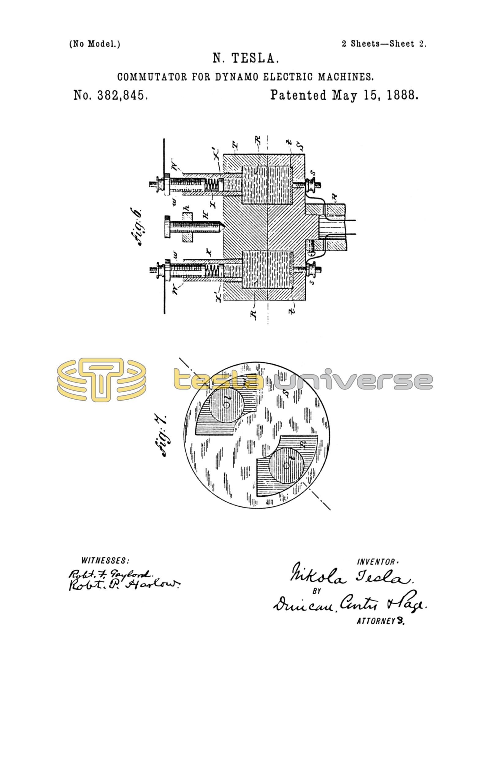
Figure 1 is a central longitudinal section of the end of a shaft with my improved commutator carried thereon. Fig. 2 is a view of the inner or bearing face of the collector. Fig. 3 is an end view from the armature side of a modified form of commutator. Figs. 4 and 5 are views of details of Fig. 3. Fig. 6 is a longitudinal central section of another modification, and Fig. 7 is a sectional view of the same.
A is the end of the armature-shaft of a dynamo-electric machine or motor.
A' is a sleeve of insulating material around the shaft, secured in place by a screw, a', or by other suitable means.
The commutator proper is in the form of a disk which is made up of four segments, D D' G G', similar to those shown in Fig. 3. Two of these segments, as D D', are of metal and are in electrical connection with the ends of the coils on the armature. The other two segments are of insulating material. The segments are held in place by a band, B, of insulating material. The disk is held in place by friction or by screws, such as g' g', Fig. 3, which secure the disk firmly to the sleeve A'.
The collector is made in the same form as the commutator. It is composed of the two metallic segments E E' and the two insulating segments F F', bound together by a band, C. The metallic segment E E' are of the same or practically the same width or extent as the insulating segments or spaces of the commutator. The collector is secured to a sleeve, B', by screws g g, and the sleeve is arranged to turn freely on the shaft A. The end of the sleeve B' is closed by a plate, as f, upon which presses a pivot-pointed screw, h, adjustable in a spring, H, which acts to maintain the collector in close contact with the commutator and to compensate for the play of the shaft. Any convenient means is employed to hold the collector so that it may not turn with the shaft. For example, I have shown a slotted plate, K, which is designed to be attached to a stationary support, and an arm extending from the collector and carrying a clamping-screw, L, by which the collector may be adjusted and set to the desired position.
I prefer in the form shown in Figs. 1 and 2 to fit the insulating-segments of both commutator and collector loosely and to provide some means—as, for example, light springs e e, secured to the bands A' B', respectively, and bearing against the segments—to exert a light pressure upon them and keep them in close contact and to compensate for wear. The metal segments of the commutator may be moved forward by loosening the screw a'.
The circuit or line wires are led from the metal segments of the collector, being secured thereto in any convenient manner, the plan of connections being shown as applied to a modified form of the commutator in Fig. 6. The commutator and the collector in thus presenting two flat and smooth bearing-surfaces prevent by mechanical action the occurrence of sparks, and this is more effectively accomplished as is here done—that is to say, by the interposition of an insulating body between the separating plates or segments of the commutator and collector—than by any other mechanical devices of which I am aware.
The insulating-segments are made of some hard material capable of being polished and formed with sharp edges. Such materials as glass, marble, or soapstone may be advantageously used. The metal segments are preferably of copper or brass; but they may have a facing or edge of durable material—such as platinum or the like—where the sparks are liable to occur.
In Fig. 3 a somewhat modified form of my invention is shown, a form designed to facilitate the construction and replacing of the parts. In this form the commutator and collector are made in substantially the same manner as previously described, except that the bands B C may be omitted. The four segment of each part, however, are secured to their respective sleeves by screws g' g', and one edge of each segment is cut away, so that small plates a b may be slipped into the spaces thus formed. Of these plates a a are of metal, and are in contact with the metal segments D D', respectively. The other two, b b, are of glass or marble, and they are all preferably square, as shown in Figs. 4 and 5, so that they may be turned to present new edges should any edge become worn by use. Light springs d bear upon these plates and press those in the commutator toward those in the collector, and insulating-strips c c are secured to the periphery of the disks to prevent the blocks from being thrown out by centrifugal action. These plates are, of course, useful at those edges of the segments only where sparks are liable to occur, and, as they are easily replaced, they are of great advantage. I prefer to coat them with platinum or silver.
In Fig. 6 and 7 is shown the construction which I use when, instead of solid segments, a fluid is employed. In this case the commutator and collector are made of two insulating-disks, S T, and in lieu of the metal segments a space is cut out of each part, as at R R', corresponding in shape and size to a metal segment. The two parts are fitted smoothly and the collector T held by the screws h and spring H against the commutator S. As in the other cases, the commutator revolves while the collector remains stationary, The ends of the coils are connected to binding-posts s s, which are in electrical connection with metal plates t t within the recesses in the two parts S T. These chambers or recesses are filled with mercury, and in the collector part are tubes W W, with screws w w, carrying springs X and pistons X', which compensate for the expansion and contraction of the mercury under varying temperatures, but which are sufficiently strong not to yield to the pressure of the fluid due to centrifugal action, and which serve as binding-posts.
In all the above cases I have described commutators adapted for a single coil, and the device is particularly adapted to such purposes. The number of segments may be increased, however, or more than one commutator used with a single armature, as will be well understood.
Although I have shown the bearing-surface as planes at right angles to the shaft or axis, it is evident that in this particular the construction may be very greatly modified without departure from the invention.
Without confining myself, therefore, to the details of construction which I have shown in illustration of the invention, what I claim as new is—
1. In a dynamo-electric machine, the combination, with a commutator formed with conducting terminals or segments with intervening insulating-spaces, of a collector adapted to bear upon the surface of the commutator, and formed with conducting terminals or segments equal in extent to the insulating-space between the commutator-segments, as set forth.
2. The combination, with a commutator built or formed of alternate blocks or segments of conducting and insulating material, of a collector adapted to bear upon the surface of the commutator and formed of conducting blocks or segments of a width or extent equal to that of the insulating-segments of the commutator and separated by interposed blocks or segments of insulating material, as described.
3. The combination, with a commutator formed as a disk with alternate terminals or segments of conducting and insulating material, of a collector similarly formed and mounted with its face in contact with that of the commutator, as set forth.
4. The combination, with a commutator having a bearing-surface formed of alternate sections of conducting and insulating material, of a collector with a similar and symmetrically formed bearing-surface and means for applying spring-pressure to force the two bearing-surfaces together, as set forth.
5. The combination, with a commutator and a collector the bearing-surfaces of which are identical in respect to the disposition of the conducting and insulating parts, of means for applying spring-pressure to maintain the two bearing-surfaces in contact and means for holding the collector against rotary movement, as set forth.
Signed by me this 21st day of April, 1887.
NIKOLA TESLA.
ROBT. F. GAYLORD,
FRANK E. HARTLEY.