Nikola Tesla Patents
Nikola Tesla U.S. Patent 416,195 - Electro-Magnetic Motor
NIKOLA TESLA, OF NEW YORK, N. Y., ASSIGNOR TO THE TESLA ELECTRIC COMPANY, OF SAME PLACE.
ELECTRO-MAGNETIC MOTOR.
SPECIFICATION forming part of Letters Patent No. 416,195, dated December 3, 1889.
Application filed May 20, 1889. Serial No. 311,419. (No model.)
To all whom it may concern:
Be it known that I, NIKOLA TESLA, a subject of the Emperor of Austria, from Smiljan, Lika, border country of Austria-Hungary, residing at New York, in the county and State of New York, have invented certain new and useful Improvements in Electro-Magnetic Motors, of which the following is a specification, reference being had to the drawings accompanying and forming a part of the same.
This invention relates to that form of alternating-current motor invented by me, in which there are two or more energizing-circuits through which alternating currents differing in phase are caused to pass. I have in prior patents and applications shown various forms or types of this motor—first, motors having two or more energizing-circuits of the same electrical character, and in the operation of which the currents used differ primarily in phase; second, motors with a plurality of energizing-circuits of different electrical character, in or by means of which the difference of phase is produced artificially, and, third, motors with a plurality of energizing-circuits, the currents in one being induced from currents in another. I shall hereinafter show the application of my present invention to these several types. Considering the structural and operative conditions of any one of them—as, for example, that first-named—the armature which is mounted to rotate in obedience to the co-operative influence or action of the energizing-circuits has coils wound upon it which are closed upon themselves and in which currents are induced by the energizing-currents with the object and result of energizing the armature-core; but under any such conditions as must exist in these motors it is obvious that a certain time must elapse between the manifestations of an energizing-current impulse in the field-coils, and the corresponding magnetic state or phase in the armature established by the current induced thereby; consequently a given magnetic influence or effect in the field which is the direct result of a primary-current impulse will have become more or less weakened or lost before the corresponding effect in the armature indirectly produced has reached its maximum. This is a condition unfavorable to efficient working in certain cases—as, for instance, when the progress of the resultant poles or points of maximum attraction is very great, or when a very high number of alternations is employed—for it is apparent that a stronger tendency to rotation will be maintained if the maximum magnetic attractions or conditions in both armature and field coincide, the energy developed by a motor being measured by the product of the magnetic quantities of the armature and field.
The object, therefore, in this invention is to so construct or organize these motors that the maxima of the magnetic effects of the two elements—the armature and field—shall more nearly coincide. This I accomplish in various ways, which I may best explain by reference to the drawings, in which various plans for accomplishing the desired results are illustrated.
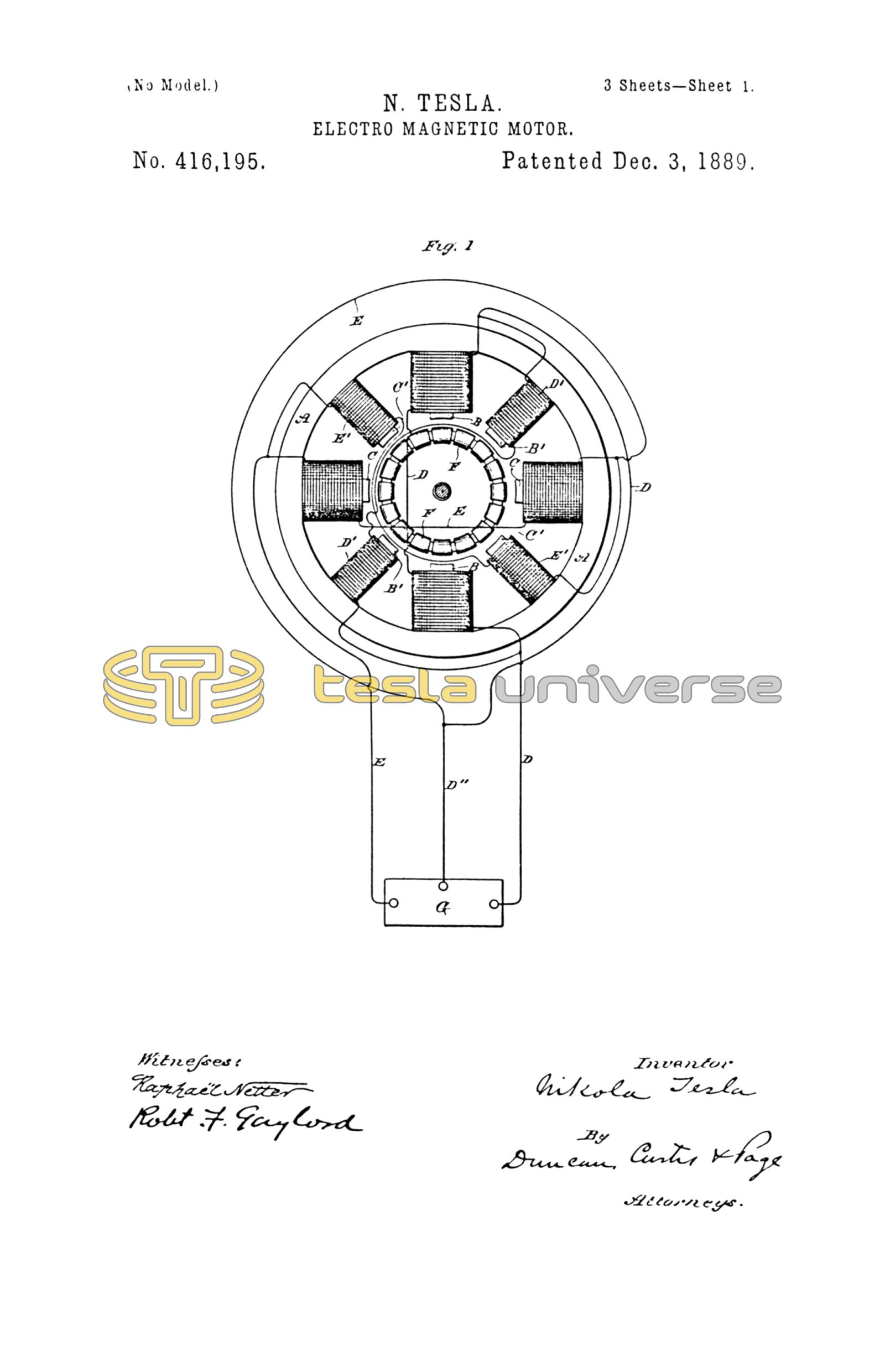
Figure 1: This is a diagrammatic illustration of a motor system such as I have described in my prior patents, and in which the alternating currents proceed from independent sources and differ primarily in phase.
A designates the field-magnet or magnetic frame of the motor; B B, oppositely-located pole-pieces adapted to receive the coils of one energizing-circuit; and C C, similar pole-pieces for the coils of the other energizing-circuit. These circuits are designated, respectively, by D E, the conductor D'' forming a common return to the generator G. Between these poles is mounted an armature—for example, a ring or annular armature, wound with a series of coils F, forming a closed circuit or circuits. The action or operation of a motor thus constructed is now well understood. It will be observed, however, that the magnetism of poles B, for example, established by a current-impulse in the coils thereon, precedes the magnetic effect set up in the armature by the induced current in coils F. Consequently the mutual attraction between the armature and field-poles is considerably reduced. The same conditions will be found to exist if, instead of assuming the poles B or C as acting independently, we regard the ideal resultant of both acting together, which is the real condition. To remedy this, I construct the motor-field with secondary poles B' C', which are situated between the others. These pole-pieces I wind with coils D' E', the former in derivation to the coils D, the latter to coils E. The main or primary coils D and E are wound for a different self-induction from that of the coils D' and E', the relations being so fixed that if the currents in D and E differ, for example, by a quarter-phase, the currents in each secondary coil, as D' E', will differ from those in its appropriate primary D or E by, say, forty-five degrees, or one-eighth of a period.
I explain the action of this motor as follows: Assuming that an impulse or alternation in circuit or branch E is just beginning while in the branch D it is just falling from maximum, the conditions of a quarter-phase difference. The ideal resultant of the attractive forces of the two sets of poles B C therefore may be considered as progressing from poles B to poles C while the impulse in E is rising to maximum and that in D is falling to zero or minimum. The polarity set up in the armature, however, lags behind the manifestations of field magnetism, and hence the maximum points of attraction in armature and field, instead of coinciding, are angularly displaced. This effect is counteracted by the supplemental poles B' C'. The magnetic phases of these poles succeed those of poles B C by the same, or nearly the same, period of time as elapses between the effect of the poles B C and the corresponding induced effect in the armature; hence the magnetic conditions of poles B' C' and of the armature more nearly coincide and a better result is obtained. As poles B' C' act in conjunction with the poles in the armature established by poles B C, so in turn poles C B act similarly with the poles set up by B' C', respectively. Under such conditions the retardation of the magnetic effect of the armature and that of the secondary poles will bring the maximum of the two more nearly into coincidence and a correspondingly-stronger torque or magnetic attraction secured.
In such a disposition as is shown in Fig. 1 it will be observed that as the adjacent pole-pieces of either circuit are of like polarity they will have a certain weakening effect upon one another. I therefore prefer to remove the secondary poles from the direct influence of the others. This I may do by constructing a motor with two independent sets of fields, and with either one or two armatures electrically connected, or by using two armatures and one field. These modifications will be illustrated hereinafter.
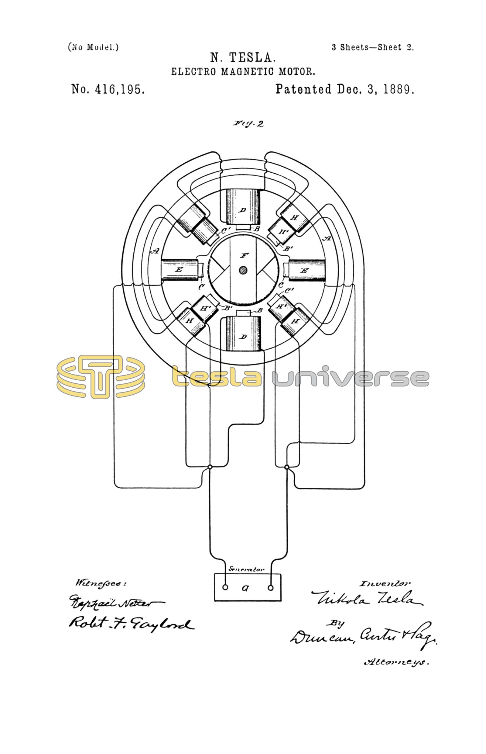
Fig. 2 is a diagrammatic illustration of a motor and system in which the difference of phase is artificially produced. There are two coils D D in one branch and two coils E E in the other branch of the main circuit from the generator G. These two circuits or branches are of different self-induction, one, as D, being higher than the other. For convenience I have indicated this by making coils D much larger than coils E. By reason of this difference in the electrical character of the two circuits the phases of current in one are retarded to a greater extent than the other. Let this difference be thirty degrees. A motor thus constructed will rotate under the action of an alternating current; but as happens in the case previously described the corresponding magnetic effects of the armature and field do not coincide owing to the time that elapses between a given magnetic effect in the armature and the condition of the field that produces it. I therefore employ the secondary or supplemental poles B' C'. There being thirty degrees difference of phase between the currents in coils D E, the magnetic effects of poles B' C' should correspond to that produced by a current differing from the current in coils D or E by fifteen degrees. This I may accomplish by winding each supplemental pole B' C' with two coils H H'. The coils H are included in a derived circuit having the same self-induction as circuit D, and coils H' in a circuit having the same self-induction as circuit E, so that if these circuits differ by thirty degrees the magnetism of poles B' C' will correspond to that produced by a current differing from that in either D or E by fifteen degrees. This is true in all other cases. For example, if in Fig. 1 the coils D' E' be replaced by the coils H H' included in derived circuits, the magnetism of the poles B' C' will correspond in effect or phase, if it may be so termed, to that produced by a current differing from that in either circuit D or E by forty-five degrees, or one-eighth of a period.
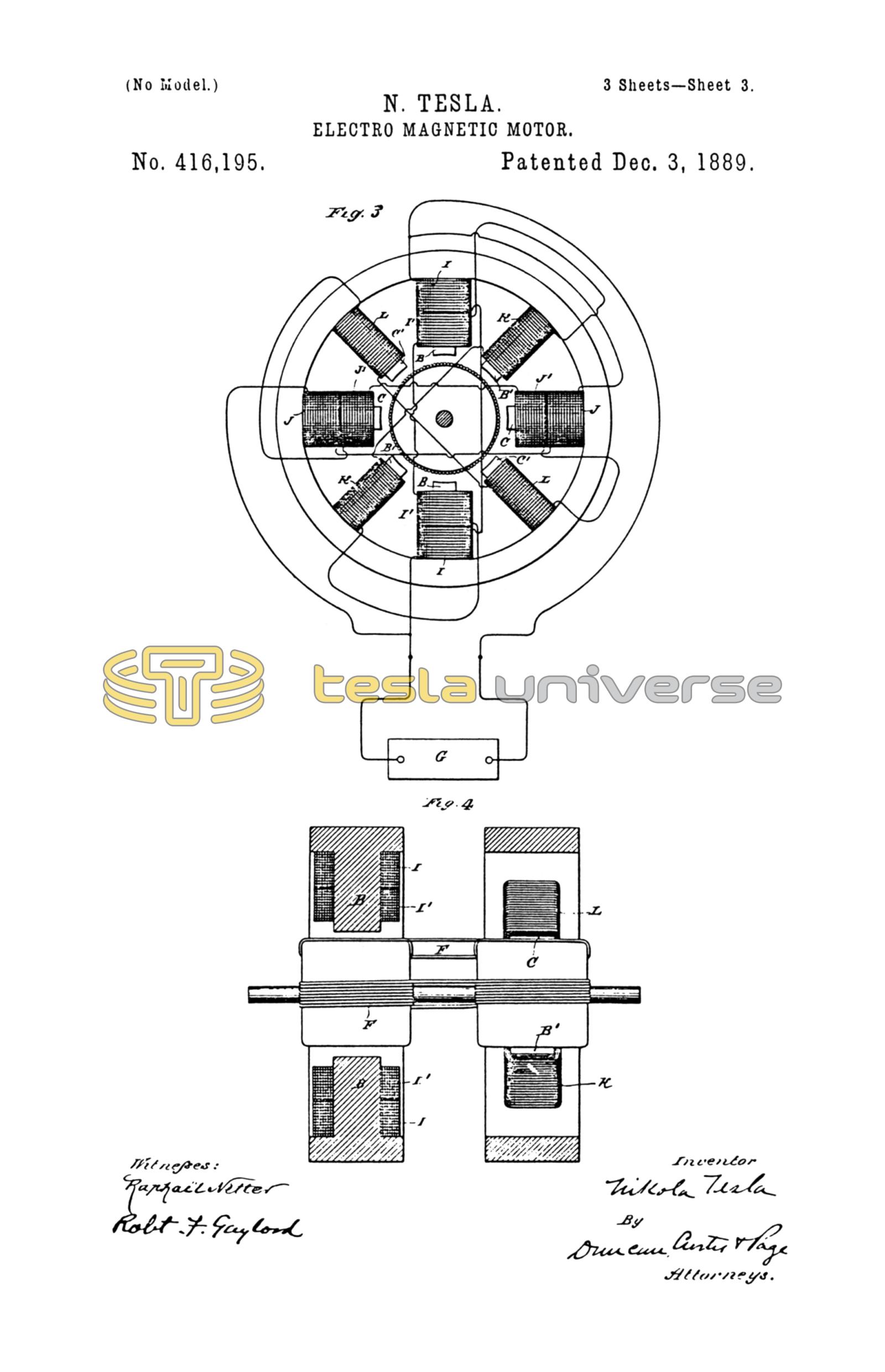
This invention as applied to a derived-circuit motor is illustrated in Figs. 3 and 4. The former is an end view of the motor with the armature in section and a diagram of connections, and Fig. 4 a vertical section through the field. These figures are also drawn to show one of the dispositions of two fields that may be adopted in carrying out the invention. The poles B B C C are in one field, the remaining poles in the other. The former are wound with primary coils I J and secondary coils I' J', the latter with coils K L. The primary coils I J are in derived circuits, between which, by reason of their different self-induction, there is a difference of phase, say, of thirty degrees. The coils I' K are in circuit with one another, as also are coils J' L, and there should be a difference of phase between the currents in coils K and L and their corresponding primaries of, say, fifteen degrees. If the poles B C are at right angles, the armature-coils should be connected directly across, or a single armature-core wound from end to end may be used; but if the poles B C be in line there should be an angular displacement of the armature-coils, as will be well understood.
The operation will be understood from the foregoing. The maximum magnetic condition of a pair of poles, as B' B', coincides closely with the maximum effect in the armature, which lags behind the corresponding condition in poles B B.
There are many other ways of carrying out this invention, but they all involve the same broad principle of construction and operation.
In using expressions herein to indicate a coincidence of the magnetic phases or effects in one set of field-magnets with those set up in the armature by the other I refer only to approximate results; but this of course will be understood.
What I claim is—
1. In an alternating-current motor, the combination, with an armature wound with closed coils, of main and supplemental field magnets or poles, one set of which is adapted to exhibit their maximum magnetic effect simultaneously with that set up in the armature by the action of the other, as set forth.
2. In an electro-magnetic motor, the combination, with an armature, of a plurality of field or energizing coils included, respectively, in main circuits adapted to produce a given difference of phase and supplemental or secondary circuits adapted to produce an intermediate difference of phase, as set forth.
NIKOLA TESLA.
R. J. STONEY, Jr.,
JOHN GILLESPIE.