Nikola Tesla Patents
Nikola Tesla U.S. Patent 433,700 - Alternating-Current Electro-Magnetic Motor
NIKOLA TESLA, OF NEW YORK, N. Y., ASSIGNOR TO THE TESLA ELECTRIC COMPANY, OF SAME PLACE.
ALTERNATING-CURRENT ELECTRO-MAGNETIC MOTOR.
SPECIFICATION forming part of Letters Patent No. 433,700, dated August 5, 1890.
Application filed May 26, 1890. Serial No. 345,388. (No model.)
To all whom it may concern:
Be it known that I, NIKOLA TESLA, a subject of the Emperor of Austria-Hungary, from Smiljan, Lika, border country of Austria-Hungary, residing at New York, in the county and State of New York, have invented certain new and useful Improvements in Alternating-Current Electro-Magnetic Motors, of which the following is a specification, reference being had to the drawings accompanying and forming a part of the same.
This invention is an improvement in that class of electro-magnetic motors in which the rotation is produced by the progressive movement or effect of the maximum magnetic points or poles produced by the conjoint action or effect of two energizing-circuits through which are passed alternating currents, or currents of rapidly-varying strength of a kindred nature.
The improvements subject of this application are more particularly applicable to that class of motors in which two or more sets of energizing-magnets are employed, and in which by artificial means a certain interval of time is made to elapse between the respective maximum or minimum periods or phases of their magnetic attraction or effect. This interval or difference in phase between the two sets of magnets, when artificially produced, is limited in extent. It is desirable, however, for the economical working of such motors that the strength or attraction of one set of magnets should be maximum at the time when that of the other set is minimum and conversely; but these conditions have not heretofore been realized except in cases where the two currents have been obtained from independent sources in the same or different machines.
The object of the present invention is to establish conditions more nearly approaching the theoretical requirements of perfect working, or, in other words, to produce artificially a difference of magnetic phase by means of a current from a single primary source sufficient in extent to meet the requirements of practical and economical working.
In carrying out my invention I employ a motor with two sets of energizing or field magnets, each wound with coils connected with a source of alternating or rapidly-varying currents, but forming two separate paths or circuits. The magnets of one set I protect to a certain extent from the energizing action of the current by means of a magnetic shield or screen interposed between the magnet and its energizing-coil. This shield is properly adapted to the conditions of particular cases, so as to shield or protect the main core from magnetization until it has become itself saturated and no longer capable of containing all the lines of force produced by the current. By this means it will be seen that the energizing action begins in the protected set of magnets a certain arbitrarily-determined period of time later than in the other, and that by this means alone or in conjunction with other means or devices heretofore employed a practically-economical difference of magnetic phase may readily be secured.
The nature and operation of the invention will be more fully explained by reference to the accompanying drawings.
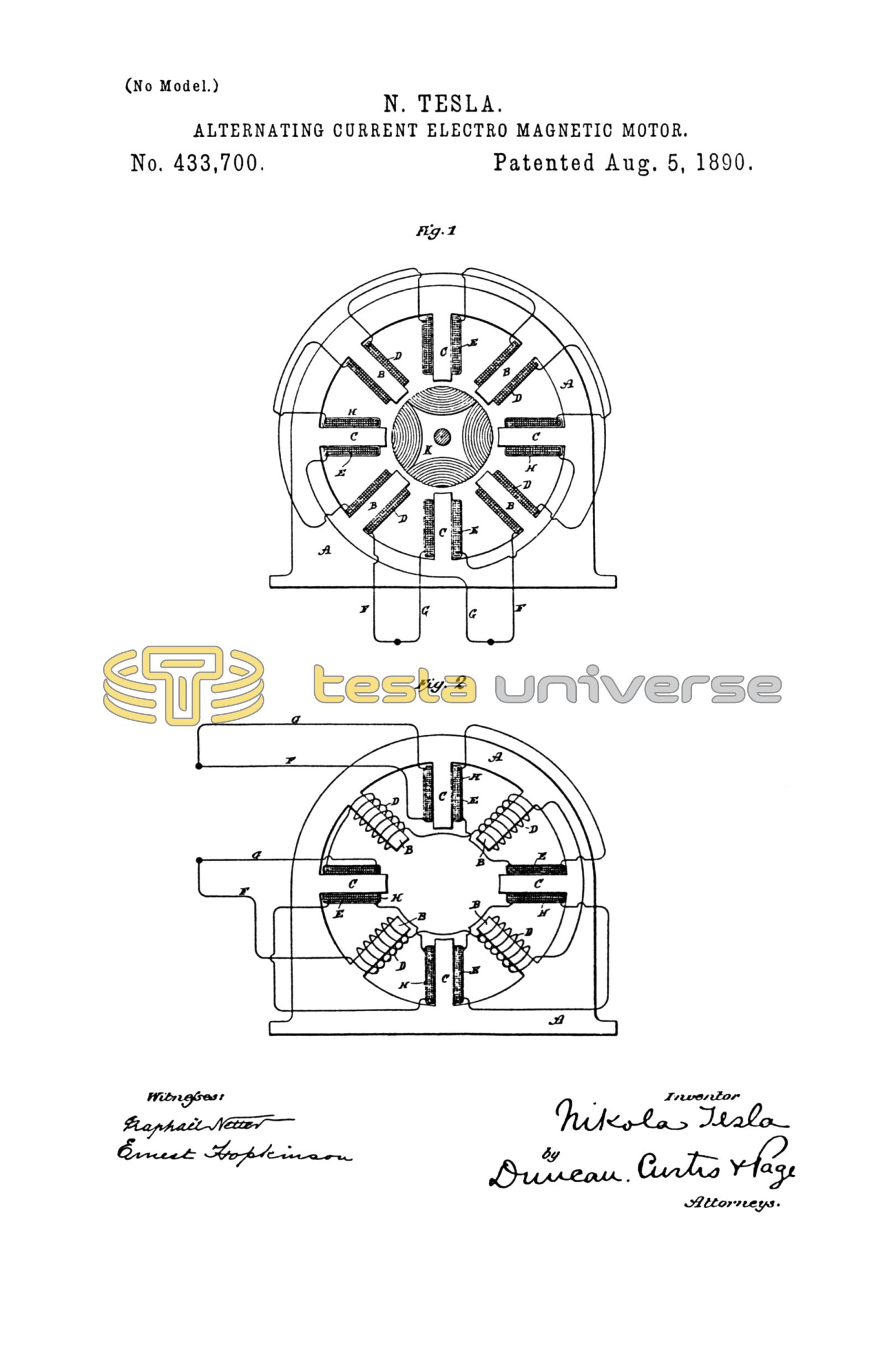
Figure 1 is a view of a motor, partly in section, with a diagram illustrating the invention. Fig. 2 is a similar view of a modification of the same.
In Fig. 1, which exhibits the simplest form of the invention, A A is the field-magnet of a motor, having, say, eight poles or inwardly-projecting cores B and C. The cores B form one set of magnets and are energized by coils D. The cores C, forming the other set, are energized by coils E, and the coils are connected, preferably, in series with one another, in two derived or branched circuits F G, respectively, from a suitable source of current. Each coil E is surrounded by a magnetic shield H, which is preferably composed of an annealed, insulated, or oxidized iron wire wrapped or wound on the coils in the manner indicated, so as to form a closed magnetic circuit around the coils and between the same and the magnetic cores C. Between the pole pieces or cores B C is mounted the armature K, which, as is usual in this type of machines, is wound with coils L closed upon themselves. The operation resulting from this disposition is as follows: If a current impulse be directed through the two circuits of the motor, it will quickly energize the cores B, but not so the cores C, for the reason that in passing through the coils E there is encountered the influence of the closed magnetic circuits formed by the shields H. The first effect is to effectively retard the current impulse in circuit G, while at the same time the proportion of current which does pass does not magnetize the cores C, which are shielded or screened by the shields H. As the increasing electro-motive force then urges more current through the coils E, the iron wire H becomes magnetically saturated and incapable of carrying all the lines of force, and hence ceases to protect the cores C, which become magnetized, developing their maximum effect after an interval of time subsequent to the similar manifestation of strength in the other set of magnets, the extent of which is arbitrarily determined by the thickness of the shield H, and other well-understood conditions.
From the above it will be seen that the apparatus or device acts in two ways. First, by retarding the current, and, second, by retarding the magnetization of one set of the cores, from which its effectiveness will readily appear.
Many modifications of the principle of this invention are possible. One useful and efficient application of the invention is shown in Fig. 2. In said figure a motor is shown similar in all respects to that above described, except that the iron wire H, which is wrapped around the coils E, is in this case connected in series with the coils D. The iron-wire coils H, are connected and wound, so as to have little or no self-induction, and being added to the resistance of the circuit F the action of the current in that circuit will be accelerated, while in the other circuit G it will be retarded. The shield H may be made in many forms, as will be understood, and used in different ways, as appears from the foregoing description. I do not, however, limit myself to any specific form or arrangement; but
What I claim is—
1. In an alternating-current motor having two energizing-circuits, the combination, with the magnetic cores and coils of one of the circuits, of interposed magnetic shields or screens for retarding the magnetization of said cores, as set forth.
2. In an alternating-current motor having two energizing-circuits, the combination, with the magnetic cores and the coils of one of the circuits wound thereon, of magnetic shields or coils wound around said coils at right angles to their convolutions, as set forth.
3. In an alternating-current motor having two energizing-circuits, the combination, with the magnetic cores and the coils of one of the circuits which energize the said cores, of magnetic shields forming closed magnetic circuits around the coils and interposed between the coils and cores, as set forth.
4. In an alternating-current motor having two energizing-circuits derived from the same source, the combination, with the cores and the coils of one of the circuits that energizes the same, of insulated iron-wire coils wound on the said energizing-coils at right angles to their convolutions and connected up in series with the coils of the other energizing-circuit, as set forth.
NIKOLA TESLA.
ROBT. F. GAYLORD,
PARKER W. PAGE.