Nikola Tesla Patents
Nikola Tesla U.S. Patent 577,671 - Manufacture of Electrical Condensers, Coils and Similar Devices
NIKOLA TESLA, OF NEW YORK, N. Y.
MANUFACTURE OF ELECTRICAL CONDENSERS, COILS, & c.
SPECIFICATION forming part of Letters Patent No. 577,671, dated February 23, 1897.
Application filed November 5, 1896. Serial No. 611,126. (No model.)
To all whom it may concern:
Be it known that I, NIKOLA TESLA, a citizen of the United States, residing at New York, in the county and State of New York, have invented certain new and useful Improvements in the Manufacture of Electrical Condensers, Coils, and Similar Devices, of which the following is a specification, reference being had to the drawing which accompanies and forms a part of the same.
My invention is an improvement in the manufacture of electrical condensers, coils, and other devices of a similar character in which conductors designed to form paths for currents of high potential are brought into close proximity with each other. Among such devices are included many forms of condensers, transformers, self-induction coils, rheostats, and the like.
It has heretofore been shown by me that the efficiency and practicability of such devices are very greatly enhanced by the exclusion of air or gas from the dielectric separating the conductors or remote portions of the same conductor; and the object of my present improvement is to secure such exclusion of air in as perfect a manner as possible in a convenient and practicable way. To this end I place the condenser or other device to be treated in a receptacle from which the air may be more or less perfectly exhausted, and while in vacuum I introduce an insulating substance, which liquefies when subjected to heat, such as paraffin, which surrounds the said device and finds its way into its interstices.
When the device has become thoroughly saturated with the insulating material, it is allowed to cool off usually until the material begins to solidify. Air is then admitted under pressure to the receptacle containing the device and the pressure maintained until the whole mass of insulating material has solidified. By this treatment the presence of air or vacuous spaces in the dielectric, which are otherwise liable to form by the contraction of the insulating material when cooling, is prevented.
Any plan may be followed or apparatus used for securing the two conditions necessary to the attainment of the desired result; that is to say, applying the fluid insulating material in vacuum and subsequently subjecting it to or solidifying it under pressure. The degree of exhaustion or of pressure may vary, very good results being secured by a vacuum of about twenty-nine inches and a pressure of about one hundred pounds. It may be stated, however, that when hydraulic pressure is applied very much higher pressures are readily secured and are of advantage.
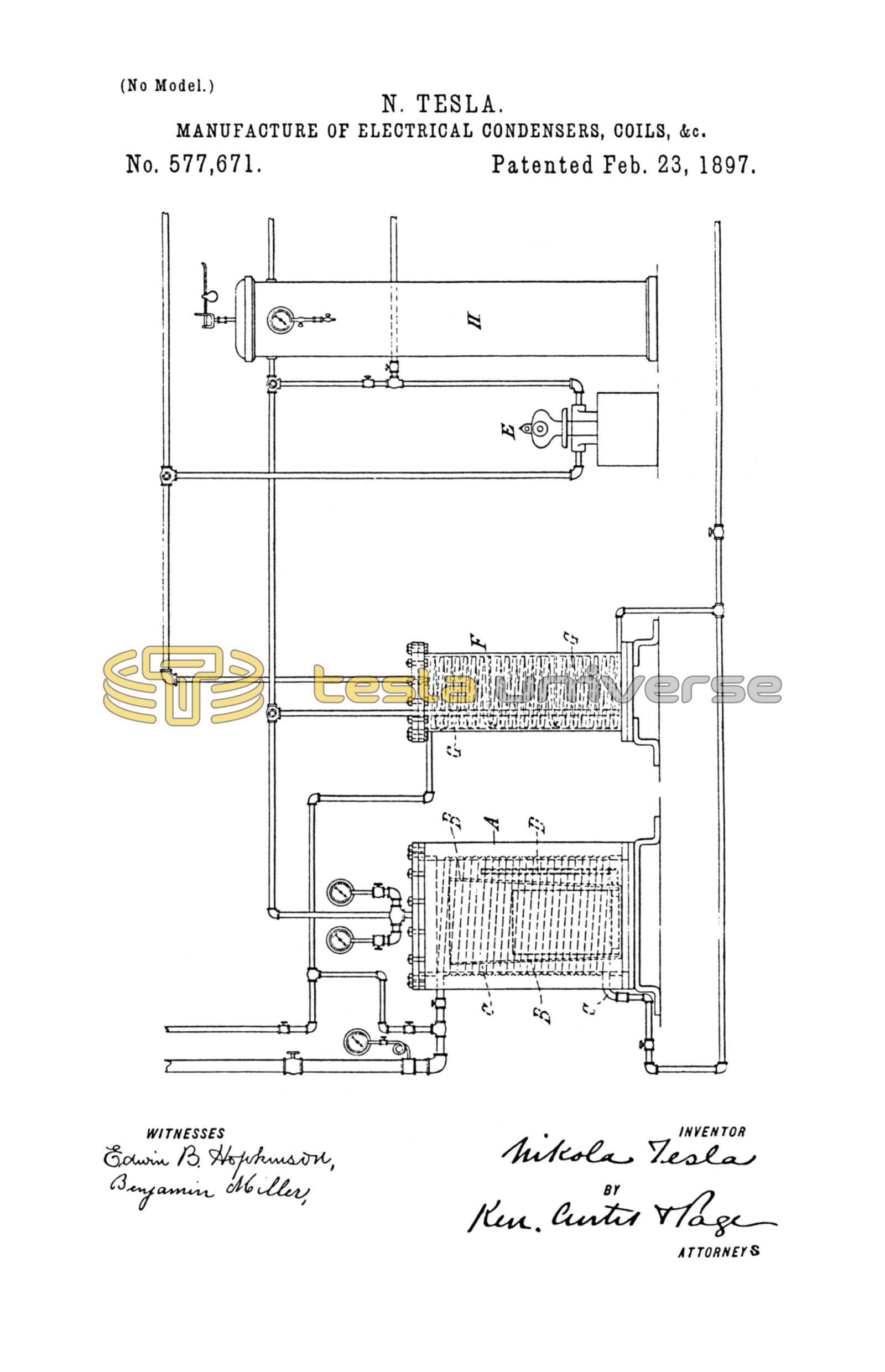
In order to facilitate the carrying out of the process, I have devised a simple and useful apparatus, which is illustrated partly in section in the accompanying drawing. As the parts of said apparatus are all of well-known construction, the apparatus as a whole will be fully understood without a full description of its details.
A is a tank or receptacle that may be closed air-tight. Within this tank is a steam-coil C, surrounding a vessel B, preferably with slightly-sloping sides and provided with a tube or pipe D, opening into it near its base.
The condenser or other device to be treated is placed in the vessel B, and around the receptacle is packed a suitable insulating material in quantity sufficient when liquefied by heat to flow through the pipe D into the vessel B and fill the space in the latter up to the top of the condenser or other device placed therein.
It is desirable to run into the pipe D enough melted material to fill it before using the apparatus and to make the pipe of a poor heat-conducting material, so that a little time will elapse after the heat is applied to melt the material in the tank A before the flow through the pipe begins.
When the apparatus has been thus prepared, the air from the interior of the tank A is withdrawn as completely as practicable by an air-pump E and steam is passed through the coil C. In order to prevent access of any of the volatile constituents of the insulating material to the pump, a condenser F, with a cooling-coil G, is interposed in the piping between the tank and pump. After a partial vacuum has been secured in the tank A and the liquefied insulating material has been run into the vessel B the pump may be stopped and the tank connected with a receiver H, from which the air has been exhausted, and the apparatus allowed to stand until all the interstices of the condenser have been permeated with the insulating material. The steam is then shut off and cold water passed through the coil C. The connections with the pump are then reversed and air is forced into the tank and receiver H and the further cooling and solidification of the insulating material carried on under a pressure considerably greater than that of the atmosphere. After the insulating material has cooled and solidified the condenser or other device, with the adhering mass of insulating material, is removed from the receptacle and the superfluous insulating material taken off.
I have found that condensers, transformers, and similar apparatus treated by this process are of very superior quality and especially suited for circuits which convey currents of high frequency and potential.
I am aware that conductors covered with a more or less porous material have been treated by placing them in a closed receptacle, exhausting the air from the receptacle, then introducing a fluid insulating compound and subjecting the same to pressure, for the purpose of more perfectly incorporating the insulating compound with the surrounding coating or covering of the conductors and causing such compound to enter the interstices in said covering, and I apply this principle of exhausting the air and introducing the fluid insulating compound under pressure in carrying out my improvement. My process, however, differs from the foregoing mainly in this, that I seek not only to fill the pores of any porous material that may be interposed between the conductors of such a device as a condenser or coil, but to fill up all the spaces in the dielectric, whereby air or vacuous spaces, the presence of which in the dielectric is so deleterious to the device, may be effectually prevented. To this end I permit the insulating compound after its incorporation with the device, under exhaustion and pressure, to cool and solidify, so that not only is the air replaced by a solid insulating compound, but the formation of vacuous spaces by the contraction of the mass on cooling prevented.
What I claim is—
The improvement in the manufacture of electrical devices such as condensers, which consists in enclosing the device in an air-tight receptacle, exhausting the air from the receptacle, introducing into a vessel containing the device an insulating material rendered fluid by heat, and then when said material has permeated the interstices of the said device, subjecting the whole to pressure, and maintaining such pressure until the material has cooled and solidified, as set forth.
NIKOLA TESLA.
M. LAWSON DYER,
PARKER W. PAGE.