
TCBA Volume 2 - Issue 1
Page 13 of 18
The Precise Measurement of Output Potentials in a Tesla Type Air Core Resonant Transformer System
(continued)
The inductance of the secondary coil can be quickly calculated by applying a variation of 3 Wheeler's formula which applies to long solenoid single layer inductors:
where: Ls = inductance of secondary coil in microhenries
r = radium of secondary coil in inches
n = number of turns
l = length of secondary coil in inches
The formula for calculating the inductance of the primary coil varies depending on the geometry/type of coil employed.* Low powered systems (2kw or less) usually employ a short solenoid and the following 4 equations works well:
(symbols and dimensional units are the same as in the above equation)
* For truncated cones (upside down helixes) use the average radius for r, i.e.,:
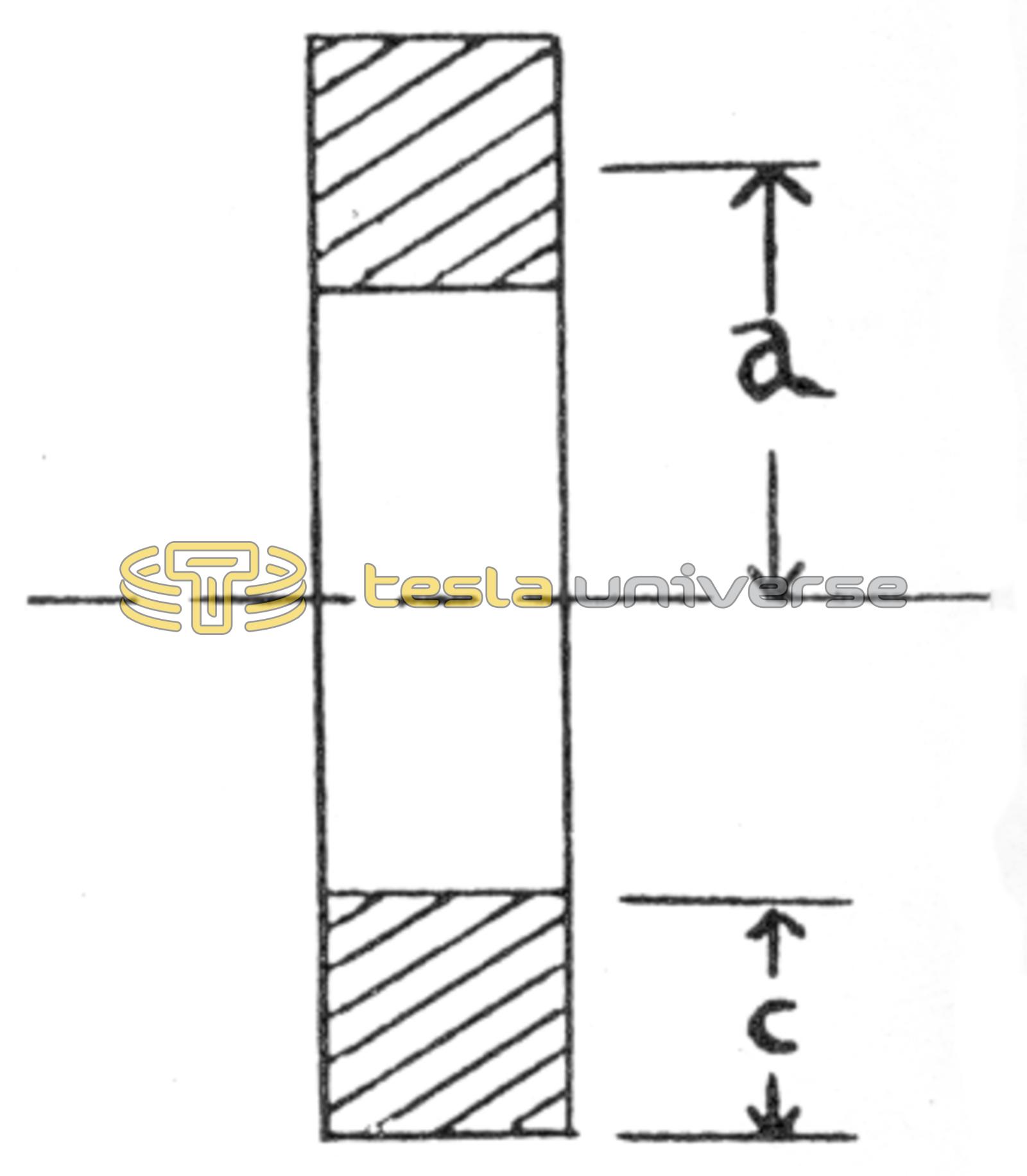
High powered coil systems usually employ a flat (Archimedean) expanding spiral often referred to as a “pancake” coil. The inductance of such flat spirals may be readily calculated by:
where: L = inductance in microhenries
a = average radius in inches as measured from central axis to middle of winding
n = number of turns
c = coil width in inches (see diagram)
This information allows one to readily calculate the maximum theoretical output of any Tesla oscillator system. This equation assumes unity coupling (1.0), and perfect resonance of both primary and secondary systems. In actual practice the output potential of a Tesla-type resonance transformer is usually 50-75% of the maximum theoretical calculated output because the coupling is always less than 1.0.