TCBA Volume 2 - Issue 1
Page 9 of 18
TCBA Member Activity
Thorn Mayes W6AX
(part 2 - continued)
If the above are not available, don't give up, for they can be easily built up from glass plates. In the spark days, photo studios were still using glass plates instead of film so there was an ample supply of 8 x 10 inch plates of excellent quality. A 6 x 8 inch sheet of aluminum foil mounted on each side of one of these plates has a capacity of .001 Mf. so 13 glass plates and foil will give .012 Mf. If the photo plates are not available, single strength window glass will stand 6,000 volts if it is bubble free.
Adjustments
Connect one lead from the condenser to the start of the inside of the primary winding. A small piece of sheet copper or brass should be mounted on the wooden support for the secondary, directly above and connected to the start of the primary winding. The lead from the lower end of the secondary winding is bent under the lower wooden head so that when the secondary is set on the primary, the two windings are connected together.
The high voltage lead from the condenser connects to one terminal of the spark gap. A clip lead from the other side, should be long enough to reach half way around the primary so correct number of turns can be selected.
Now short circuit the gap and with a grid-dip meter measure the resonant frequency of the primary circuit as primary turns are varied from one to eight. Make a plot of frequency against primary turns.
Mount the secondary on the primary making sure the wire on the bottom of the secondary rests on the primary contact. With the discharge sphere assembled on top of secondary and the primary clip lead including the estimated turns for resonance, measure the resonant frequency of the secondary. Compare this value with your curve which will indicate the correct number of primary turns. Move the clip lead to this value and repeat the grid-dip measurement and if necessary, make a final correction.
Remove the short circuit from the gap and connect the high voltage transformer leads a-cross the condenser, the grounded end to the case. To protect the transformer from kickbacks from the oscillating circuit, radio frequency chokes should be inserted in the two transformer leads. As the current is not over .030 amperes, 30 turns of #26 enameled wire wound on 3/4 inch diameter form should be adequate.
Operation
Open spark gap to 1/8 inch and apply power to the system. Final adjustment of primary turns should be made to give maximum spark length. All adjustments should be made with power disconnected as the 6,000 volt primary circuit is dangerous; direct contact across the high voltage transformer could be fatal. For maximum spark length, open the spark gap as wide as possible, still maintaining continuous operation. Turn to turn secondary sparking occurs when the primary circuit is not exactly tuned to the secondary.
Your Tesla coil is now in operation and you can enjoy the beautiful high frequency display. A fluorescent lamp lights up when brought near the resonator and it provides an easy way to draw sparks from the discharge sphere on top of the secondary. Beware of the primary circuit as it is dangerous.
This system does produce radiation that interferes with TV and radio reception. I operate mine in a room screened with 1/4 inch mesh hardware cloth. If you plan to operate for a prolonged time, the set should be screened and grounded.
The pictures were taken with TRI-X film ASA 400, 1/2 second exposure lens opening F-8 with an 80 MM lens. Longer exposure does not show the lace like formation of the individual sparks and the whole discharge become milky due to the large number of sparks recorded.
Data
- Primary - 8 turns of copper ribbon 1/2" wide
- Number of turns excited - 4
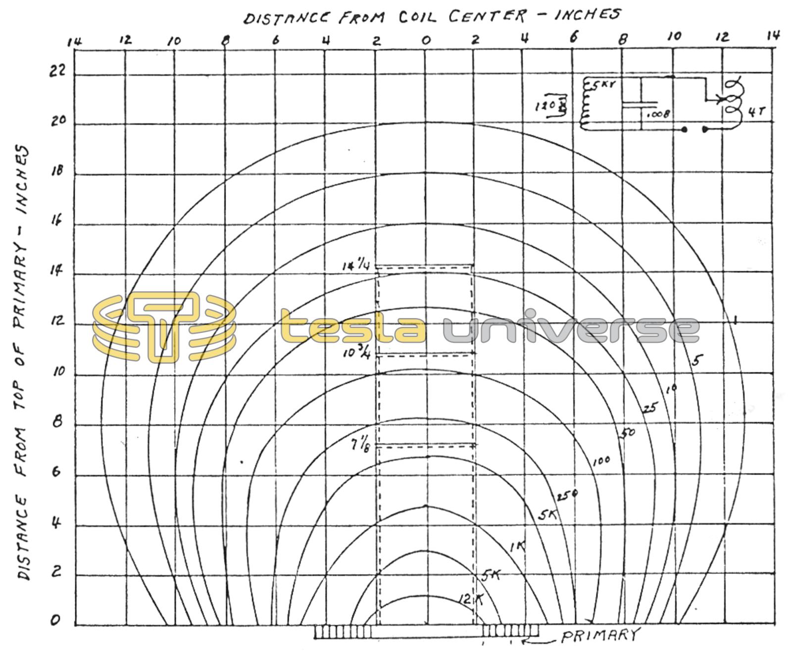
- Capacitor 0.008 mfd
- Frequency 900 KHZ
- Power input - 5000 volts at .020 amperes
- Measurements made with an absorption meter. Readings show relative field strength at the three secondary heights shown.