
Nikola Tesla Articles
Tesla's Early Work with Radio Controlled Vessels
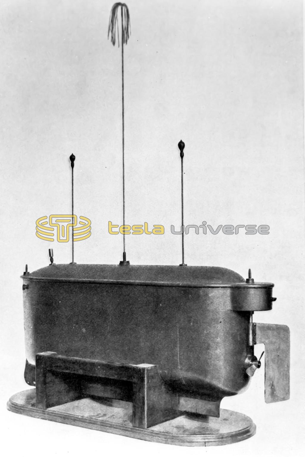
ALTHOUGH present day inventors are prone to shout loudly about their marvelous schemes for controlling torpedoes, boats or other mobile bodies by wireless, it is interesting at this time to take note of the fact that a very complete patent on an ingenious radio control system for torpedoes, etc., was issued to Nikola Tesla in the year 1898, or over eighteen years ago. At that time the science of radio telegraphy was barely on the threshold of possibilities and how far ahead of his time this great scientist is will be the more evident after perusing the following paragraphs:
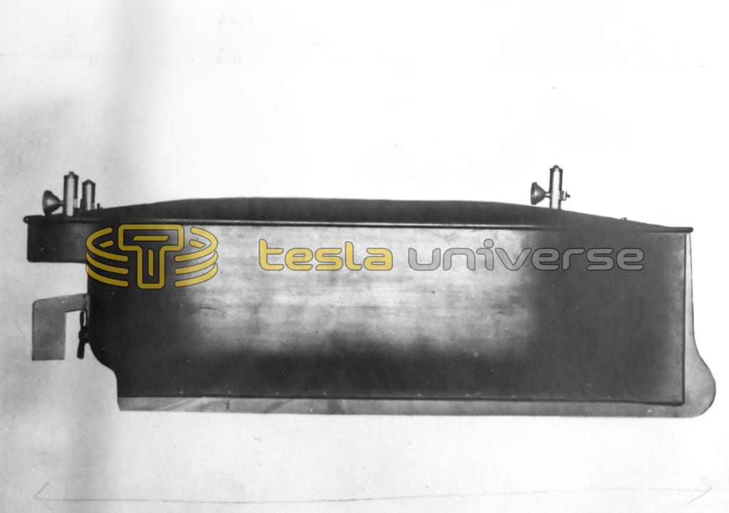
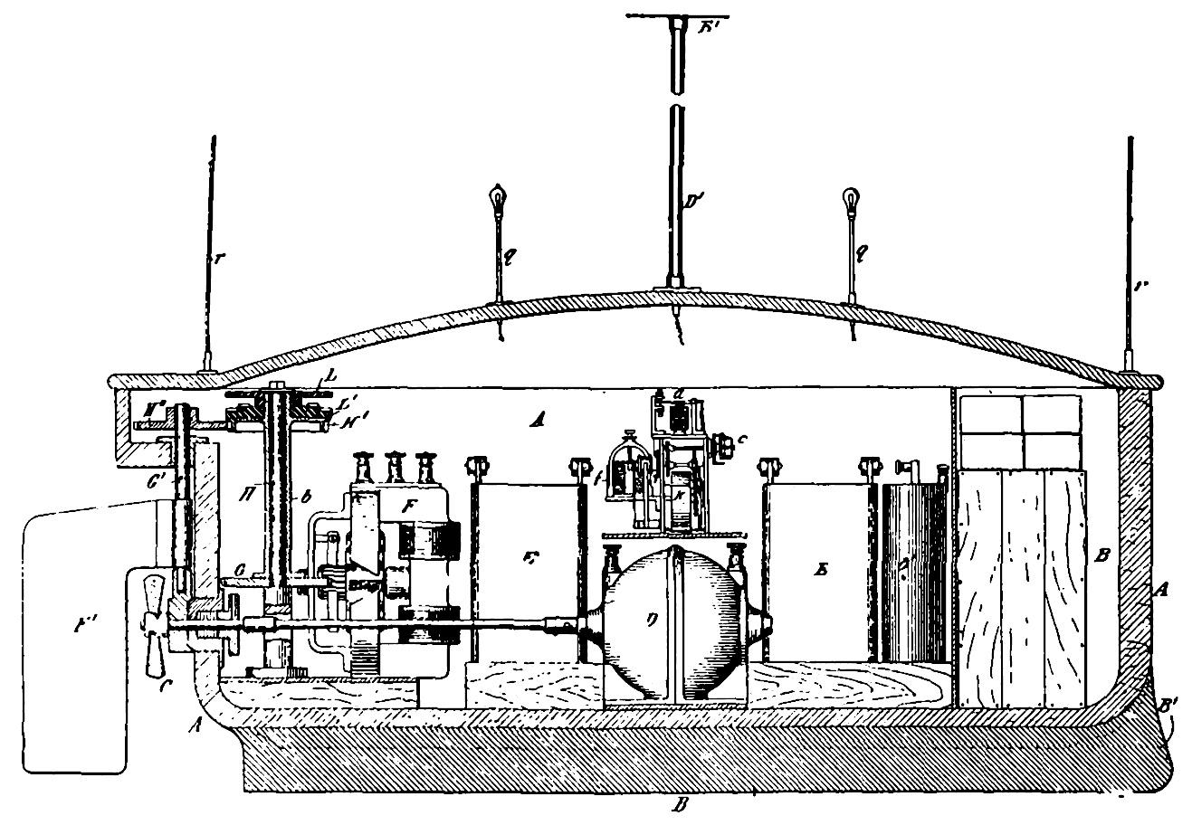
The illustrations herewith are photographs of the early models constructed by Dr. Tesla and which were actually tried out with entire success. The diagrammatic illustrations will help to explain the working parts of the telemechanical models as outlined in his patent. Fig. 1 shows a model vessel corresponding to that shown in the sectional views, while Fig. 2 represents a model constructed at an earlier date.
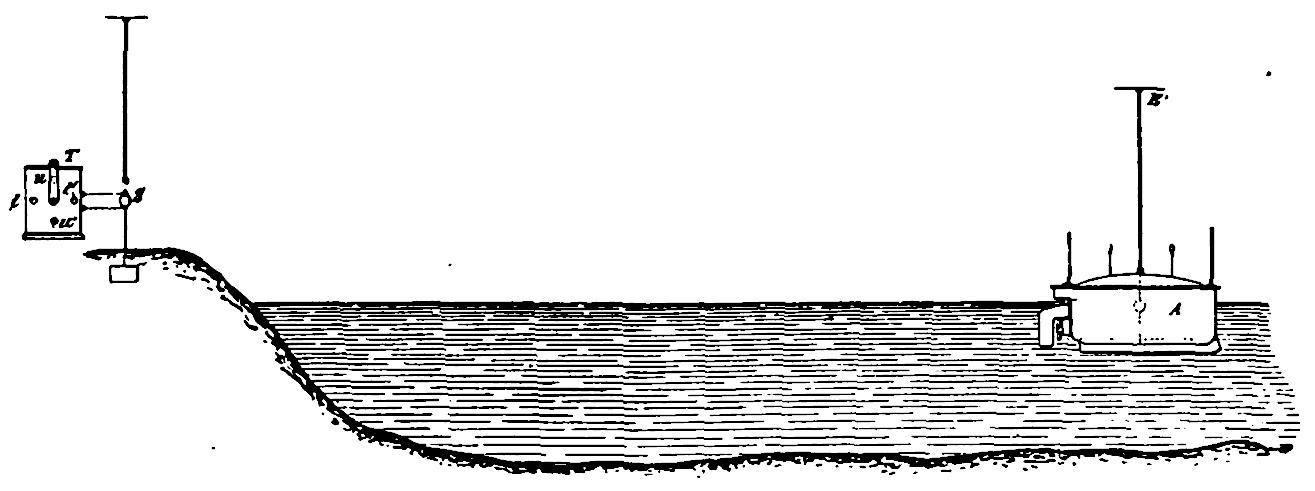
Referring to diagrams 3, 4, 5 and 6 respectively, we have in general a radio wave sensitive device resembling the well-known coherer at c. This is supported in a special movable holder on the de-cohering or resetting mechanism a and f. The radio receptor circuit connected with the coherer c leads to a grounded connection at B' (see Fig. 4), and an elevated aerial or antenna system E'. A radio transmitting station on shore utilizes a spark gap S, with an elevated aerial and ground circuit hooked-up in the usual manner. A source of high potential current at T is provided to charge the spark gap, thus sending out periodically radio waves of a given frequency. A control switch is mounted on the end of the cabinet at T, and this passes over four points T, T', U, U'. This part of the radio control arrangement will be referred to later.
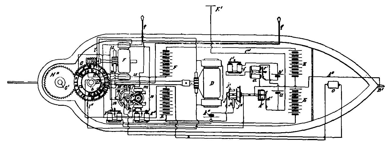
When an incoming wave passes through the coherer circuit, it causes the relay a and the de-cohering device f to function, and simultaneously a commutator device j' and j'' to rotate a quarter of a revolution for each incoming wave impulse. As will be perceived by referring to Fig. 6, it is thus possible to cause two major control relays K' and K'', to be closed alternately or again they both may be left open-circuited, and in consequence their local or armature circuits 18 and 19 will be left open. These relays control a reversible motor, F, which operates through a worm gear drive to turn from “port” to “starboard,” or vice versa, a rudder F'. Referring to Fig. 3, the worm gear for motor F moves the rudder F' through a gear H'', as becomes evident; also and simultaneously the movable sleeve b, with its attached insulated disk L' moves about the fixed vertical rod H. As perceived from the various diagrams and sectional views, this disk L' when rotated through the agency of the steering motor F, will cause a series of metal segments 9, 10, 11, etc., to pass under a set of spring metal brushes 1, 2, 3, 4, etc., which are secured to the fixed insulating member L. The movement of this connector disk controls the circuit of the propelling motor D, connected through a shaft in the usual manner to a screw-propeller C (see Fig. 3). The energy for operating the motor, etc., is obtainable from the storage or other batteries E, carried in the moving vessel.
Tesla in his early patent mentions specifically that the transmitting and receiving radio circuits should be tuned to corresponding wave lengths or at least a harmonic of same. He also mentions that it is possible (although not considered in the present discussion) to control as many as fifty or a hundred circuits, each tuned to a distinct and different transmitting wave length. Of course a different transmitting wave length would be sent out for each control step desired to be put in action at the receiving device in this case.
The coherer of this early vintage is very interesting and comprises a metal cylinder c (detail in Fig. 5), with insulating heads c', through which passes a central metallic rod c''. A small quantity of grains d, of conducting material (such as an oxidized metal) is placed in the cylinder. A metallic strip d', secured to an insulated post d'', bears against the side of the metal cylinder c, forming one part of the circuit. The central rod c'' is connected to the frame of the instrument and so to the other part of the circuit, through the forked metal arm e, the ends of which are fastened with two nuts to the projecting ends of the rod, by which means the cylinder c is supported.
In order to interrupt the flow of battery current, which is started through the action of the sensitive coherer, special means are provided, which are as follows: The armature e' of the relay magnets a, when attracted by the latter, closes a circuit containing a battery b' and magnet f. The armature-lever f' of this magnet is fixed to a rocker-shaft f'', to which is secured an anchor-escapement g. This controls the movements of a spindle g', driven by a clock-train K. The spindle g' has fixed to it a disk g'' provided with four pins b''; hence for each oscillation of the escapement g, the spindle g' is turned through one-quarter of a revolution. One of the spindles in the clock-train, as h, is geared so as to make one-half of a revolution for each quarter-revolution of spindle g'. The end of the former spindle extends through the side of the frame and carries an eccentric cylinder h', which passes through a slot in a lever h'', pivoted to the side of the frame. The forked arm e, which supports the cylinder c, is pivoted to the end of eccentric h', and the eccentric and said arm are connected by a spiral spring i. Two pins i' i' extend out from the lever h'', and one of these is always in the path of a projection on arm e. They operate to prevent the turning of cylinder c with the spindle h and the eccentric.
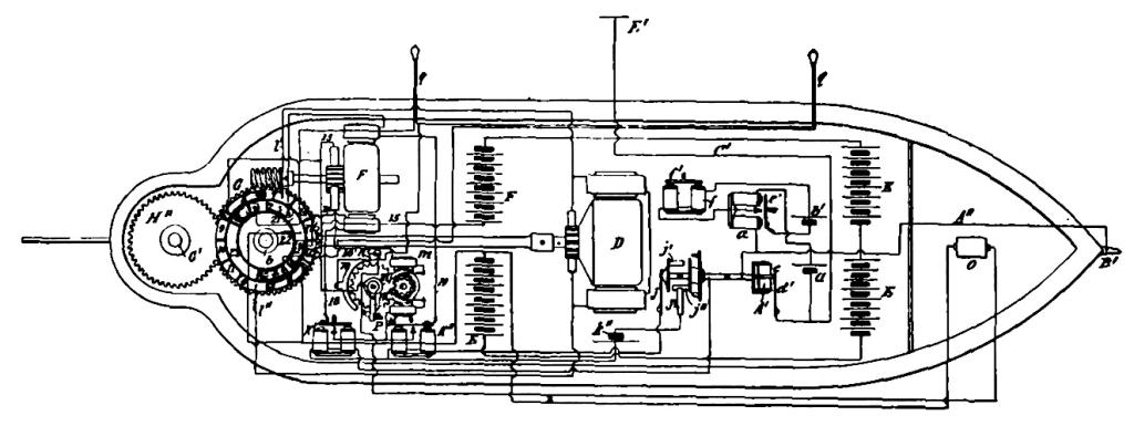
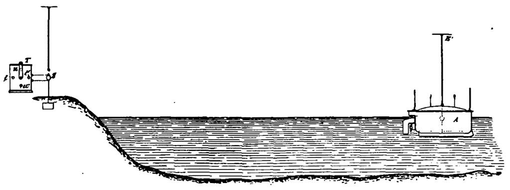
Fig. 4. Plan View of Radio-Controlled Boat and Shore Wireless Station.
It will be evident that a half-revolution of the spindle h will wind up the spring i and at the same time raise or lower the lever h'', and these parts are so arranged that just before the half-revolution of the spindle is completed the pin i', in engagement with projection or stop-pin p, is withdrawn from its path, and the cylinder c, obeying the force of the spring i, is suddenly turned end for end, its motion being checked by the other pin i'. The adjustment relatively to armature f' of magnet f is furthermore so made that the pin i' is withdrawn at the moment when the armature has nearly reached its extreme position in its approach toward the magnet — that is, when the lever l, which carries the armature f', almost touches the lower one of the two stops s s (Fig. 5), which limits its motion in both directions.
The normal position of the cylinder c is vertical, and when turned in the manner described, the grains in it are simply shifted from one end to the other; but inasmuch as they always fall through the same space and are subjected to the same agitation they are caused, after each operation of the relay, to offer precisely the same resistance to the flow of the battery current, until another radio impulse from afar reaches the receiving-circuit.
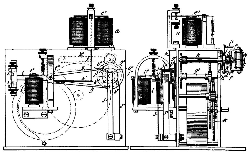
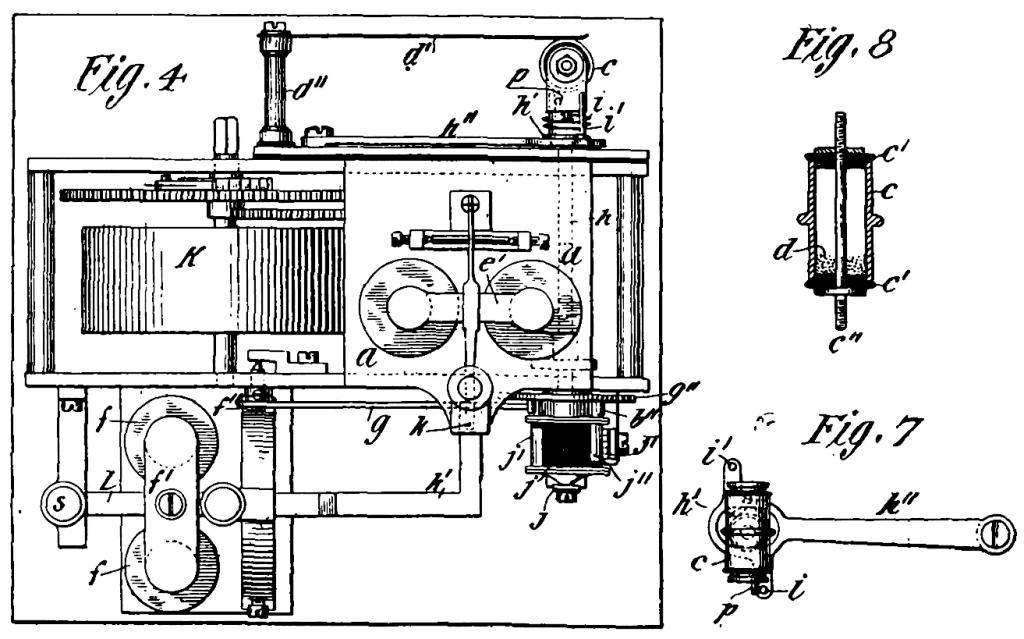
Fig. 5. Details of Clever Coherer, De-coherer and Double Relay Scheme.
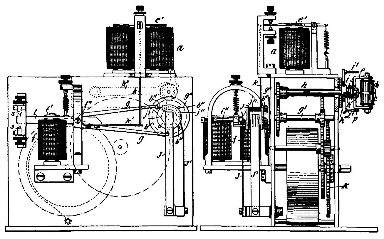
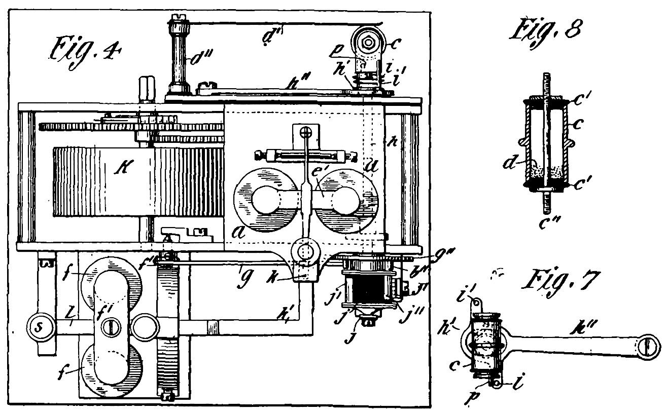
The relay-magnet a should be of such character as to respond to a very weak current and yet be positive in its action. To insure the retraction of its armature e' after the current has been established through the magnet f and interrupted by the inversion of the sensitive device c, a light rod k is supported in guides on the frame, in position to be lifted by an extension k' of the armature-lever l, and to raise slightly the armature e'. As a feeble current may normally flow through the sensitive device and the relay-magnet a, which would be sufficient to hold though not draw the armature down, it is well to observe this precaution.
The operation of the relay-magnet a, and the consequent operation of the electromagnet f, as above described, are utilized to control the operation of the propelling-engine and the steering apparatus in the following manner: On the spindle g', which carries the escapement-disk g'' (Figs. 4 and 6), is a cylinder j of insulating material, with a conducting plate or head at each end. From these two heads, respectively, contact plates or segments, j' j'' extend on diametrically opposite sides of the cylinder. The plate j'' is in electrical connection with the frame of the instrument through the head from which it extends, while insulated strips J J' bear upon the free end or head of the cylinder and the periphery of the same, respectively. Three terminals are thus provided; one always in connection with plate j', the other always in connection with the plate j'', and the third adapted to rest on the strips j' and j'' in succession, or upon the immediate insulating-spaces, according to which of the four distinct positions the commutator is brought to by the clock-train and the anchor-escapement.
At K' and K'' (Figs. 4 and 6) are two relay-magnets conveniently placed in the rear of the propelling-engine. One terminal of a battery k'' is connected to one end of each of the relay-coils, the opposite terminal to the brush J', and the opposite ends of the relay-coils to the brush J and to the frame of the instrument, respectively. As a consequence of this arrangement either the relay K' or K'' will be energized, as the brush J' bears upon the plate j' or j'', respectively; or both relays will be inactive while the brush J' bears upon an insulating-space between the plates j' and j''. While one relay, as K', is energized its armature closes a circuit through the motor F, which is rotated in a direction to throw the rudder to port. On the other hand, when relay K'' is active another circuit through the motor F is closed, which reverses its direction of rotation and shifts the rudder to starboard.
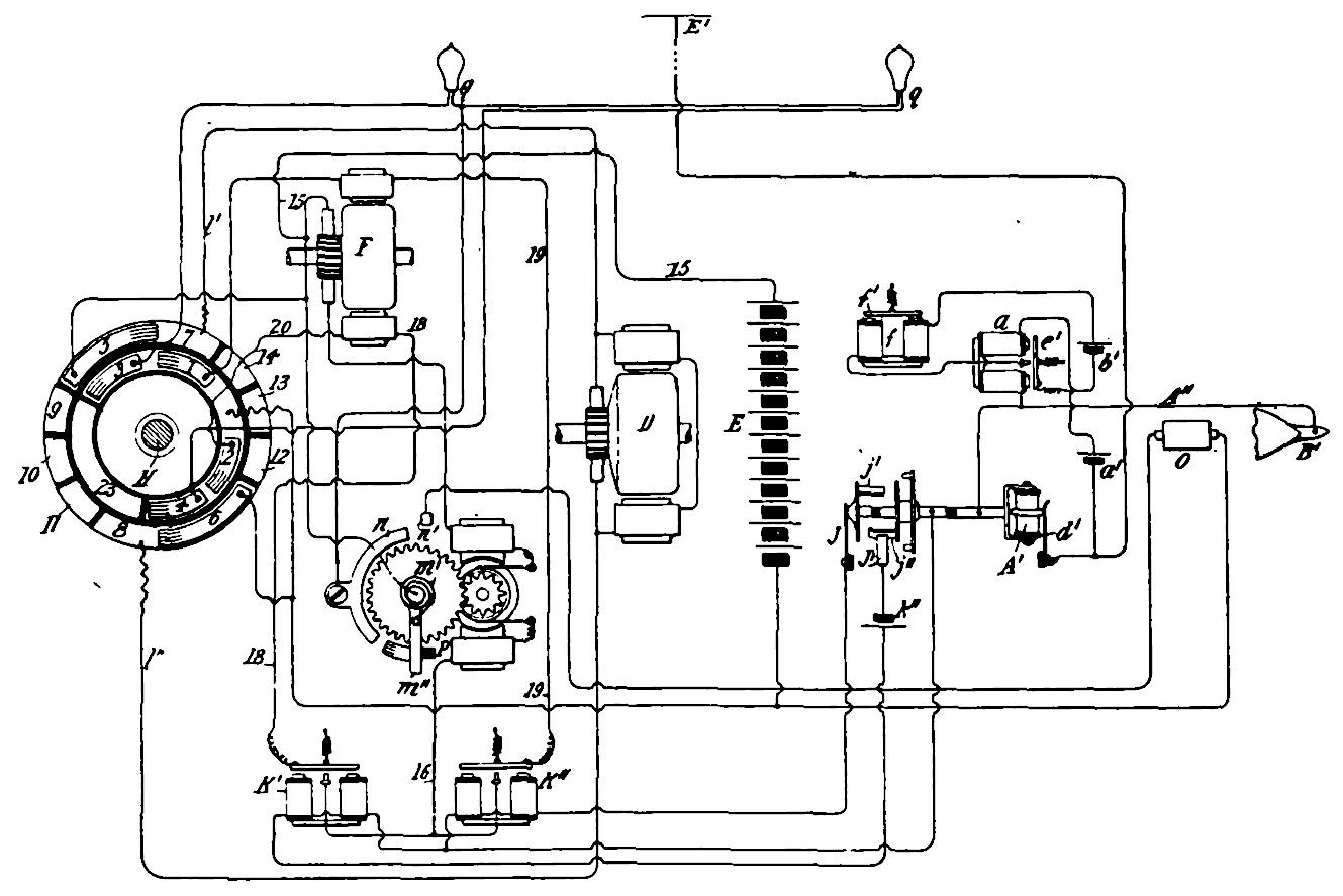
A small auxiliary motor, m, may be employed to control signaling lights erected on masts above the deck of the vessel, so that the operator on shore can tell in the dark just how and in what direction the telemechanical vessel is progressing through the water. This signaling motor arrangement is connected in series with the armature of the steering motor F, so that whenever either one of the circuits of the latter is closed through relay K' or K'', the motor m is likewise rotated, but in any case in the same direction. The signal lamps may be colored to facilitate matters. By this mechanism it is also possible, by sending out a predetermined series of electric wave impulses, to cause its spring repelled switch arm m'' to come in contact finally with switch point n', thus closing a circuit through a special device o, which might, for instance, be the detonating cap of an explosive chamber in the case of a radio-controlled torpedo.
With regard to the method of handling the entire outfit, we may now have reference to Figs. 4 and 6. Here S designates any source of electrical disturbance or oscillations, the generation of which is controlled by a suitable switch at T. The handle of the switch is movable in one direction only and stops on four points t, t', u and u', so that as the handle passes from stop to stop, oscillations are produced by the source during a very short time interval. There are thus produced four etheric wave disturbances during one revolution and the receiving-circuit is affected four times: but it will be understood from the foregoing description of the controlling devices on this vessel that the rudder will be moved twice, once to right and once to left. Preferably the handle of the switch is placed so that when it is arrested on points t t' that is to the right or left of the operator — he is reminded that the vessel is being deflected to the right or left from its course, by which means the control is naturally facilitated. The normal positions of the handle are therefore at u u' when the rudder is not acted upon, and it remains on the points u u' only so long as necessary. Since, as before stated, the working of the apparatus is quite sure, the operator is enabled to perform any such operations as provision is made for, without even seeing the vessel.
The manner of using the apparatus and the operation of the several component parts comprising the same is in detail as follows: Normally the plate L' is turned so that brush 2 rests upon the insulated segment 23 and brush 6 upon one of the insulated short segments in the rear of the circle. Under these conditions the rudder will be turned to starboard and the circuit of the propelling motor D interrupted between brushes 5 and 6. At the same time only one of the circuits of motor F — that This page finishes the article. It continues the sentence broken on page 136, and the last paragraph is the magazine’s comment, not Tesla’s.
controlled by relay K'—is capable of being closed, since brush 2, which connects with the other, is out of contact with the long segment 21.
Assuming now that it is desired to start the vessel and direct it to a given point, the handle T, at the transmitting station, is turned from its normal position on point u' to the point t on the switch-box. This sends out an electrical (etheric) disturbance, which, passing through the receiving-circuit on the vessel affects the sensitive device A' and starts the flow of current through the local circuit, including said device, the relay a, and the battery a'. This, as has been previously explained, turns the cylinder j and causes the brush J' to pass from an insulation space to the contact j'. The battery k'' is thus closed through relay K'' and the latter closes that circuit of the motor F which, starting from plate 22 (which is permanently connected with one pole of the main battery) is completed through the brush 1, the field of motor F, wire 19, the armature of relay K'', wire 16, the motor m, the brushes and commutator of motor F and wire 15 to the opposite terminal of the battery D. Motor F is thus set in operation to shift the rudder to port; but the movement of plate L' which follows, brings the brush 6 back onto segment 8 and closes the circuit of the propelling-motor which starts the vessel. The motor F is permitted to run until the rudder has been turned sufficiently to steer the vessel in the desired direction, when the transmitter handle T is turned to the point u. This produces another action of the relay a and brush J' is shifted to the insulation and both relays K' and K'' are inactive. The rudder remains in the position to which it has been shifted by the motor F. If it be then desired to shift it to “starboard,” or in the opposite direction to that in which it was last moved, the handle T is simply turned to point t' and allowed to remain there until the motor F which is now operated by relay K', the circuit of which is closed by strip J' coming into contact with plate j'', has done its work. The movement of handle T to the next point throws out both relays K' and K'', and the next movement causes a shifting of the rudder to “port,” and so on.
Suppose, however, that after the rudder has been set at any angle to its centre position, it be desired to shift it still farther in the same direction. In such case the handle is moved quickly over two points, so that the circuit which would move the rudder in the opposite direction is closed for too short a time interval to produce an appreciable effect and is allowed to rest on the third point until the rudder is shifted to the desired position, when the handle is moved to the next point, which again throws out both relays K' and K''. It will be understood that if the handle T be held for a sufficiently long time upon either point t or t', the motor F will simply turn the plate L' in one direction or the other until the circuits of motors D and F are both broken. It is furthermore evident that one relay K' or K'' will always be operative to start the motor F.
As previously explained, the longest period of operation of which the motor F is capable, under ordinary conditions of use, does not permit the motor m to shift the arm m' into contact with the plate n; but if the handle T be turned with a certain rapidity, then a series of current impulses will be directed through motor m; but as these tend to rotate the motor F in opposite directions they do not sensibly affect the latter, but act to rotate the motor m against the force of the coiled spring m'.
This invention will prove useful in many ways, says Tesla. Vessels or vehicles of any suitable kind may be used, as life, despatch or pilot boats or the like, or for carrying letters, packages, provisions, instruments, objects, or materials of any description for establishing communication with inaccessible regions and exploring the conditions existing in them, for killing or capturing whales or other animals of the sea, and for many other scientific, engineering or commercial purposes, but it could also be used in warfare, for by its certain and unlimited destructiveness it will tend to bring about and maintain permanent peace among nations.
On the contrary, however, this invention has not been commercially exploited, and Tesla’s dreams are so far unrealized.
