Nikola Tesla Articles
Tesla Circuit Controllers for Obtaining Oscillatory Currents of High Frequency
On August 16 a very ingenious and apparently significant group of patents was issued to Mr. Nikola Tesla, comprising several types of current-interrupting devices for obtaining oscillatory currents of very high frequency. Mr. Tesla has called them "electrical circuit controllers" and their use and construction may be understood by the following introductory remarks, taken from the patent specification referring to the class of circuits for which they were designed. We present also several illustrations showing the latest forms developed by Mr. Tesla, whose persistent investigations along the high frequency line entitle him to much praise and credit.
In every form of electrical apparatus involving a means for making and breaking more or less abruptly, a circuit, a waste of energy occurs during the periods of make or break, or both, due to the passage of the current through an arc formed between the receding or approaching terminals or contacts, or, more generally, through a path of high resistance. The tendency of the current to persist after the actual disjunction or to precede the conjunction of the terminals exists in varying degrees in different forms of apparatus, according to the special conditions present. For example, in the case of an ordinary induction coil the tendency to the formation of an arc at the break is, as a rule, the greater, while in certain forms of apparatus in which the discharge of a condenser is utilized this tendency is greatest at the instant immediately preceding the conjunction of the contacts of the circuit-controller which effects the discharge of the condenser.
The loss of energy occasioned by the causes mentioned may be very considerable and is generally such as to greatly restrict the use of the circuit-controller and render impossible a practical and economical conversion of considerable amounts of electrical energy by its means, particularly in cases in which a high frequency of the makes and breaks is required.
Extended experiments and investigation conducted with the aim of discovering a means for avoiding the loss incident to the use of ordinary forms of circuit-controllers have led Mr. Tesla to recognize certain laws governing the waste of energy and making it dependent chiefly on the velocity with which the terminals approach and recede from one another and also more or less on the form of the current-wave. Briefly stated, from both theoretical considerations and practical experiment, it appears that the loss of energy in any device for making and breaking a circuit, other conditions being the same, is inversely proportional rather to the square than to the first power of the speed or relative velocity of the terminals in approaching and receding from one another in an instance in which the current-curve is not so steep as to materially depart from one which may be represented by a sine function of the time; but such a case seldom obtains in practice. On the contrary, the current curve resulting from a make and break is generally very steep, and particularly so when, as in Mr. Tesla's system, the circuit-controller effects the charging and discharging of a condenser, and consequently the loss of energy is still more rapidly reduced by increased velocity of approach and separation. The demonstration of these facts and the recognition of the impossibility of attaining the desired results by using ordinary forms of circuit-controllers led Mr. Tesla to invent other means for making and breaking a circuit in which he has utilized a conducting fluid, such as mercury, as the material for one or both of the terminals and devised novel means for effecting a rapidly-intermittent contact between the fluid and a conductor or series of conductors forming the other terminal.
In this apparatus one of the members or terminals is a conducting fluid which is caused to issue from an orifice against a series of spaced conductors in rapid succession. For this purpose the series of conductors, or it may be a single conductor, is moved transversely through the stream or jet of fluid, or the jet is moved so as to impinge upon the conductors, or both jet and conductors are moved. This is preferably accomplished by mounting the conductors and the tube or duct from which the fluid issues concentrically and revolving one or both.
The plan adopted for maintaining the stream or jet of conducting fluid consists in utilizing the same power that actuates or drives the circuit-controller in effecting the necessary relative movement of its terminals to maintain the proper circulation of the conducting fluid by combining the two mechanisms (the controller and the means for maintaining a circulation of the conducting fluid) in one. This feature is of great practical advantage and may be effected in many ways. A typical arrangement for this purpose is to provide a tube or duct having an orifice at the end directed toward the spaced conductors and its other end in a position to take up a portion of the rapidly-rotating body of conducting fluid, divert it through the duct, and discharge it against the conductors. With this object when a closed receptacle is used a holder for the tube is employed, mounted within the receptacle and concentrically therewith, and this holder, when the receptacle is revolved, is held or influenced by any suitable means, as by magnetic attraction exerted from the outside or otherwise, in such manner as to keep it either in a fixed position or impress upon it a velocity different from that of the rotated fluid.
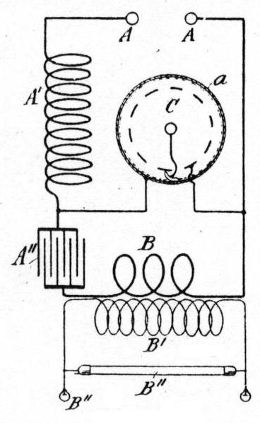
The general scheme of the system for use with which the circuit-controllers are more especially designed will be understood by referring to Fig. 1: In this figure A A represent the terminals of a source of current. A' is a self-induction or choking coil included in one branch of the circuit and permanently connected to one side of a condenser A". The opposite terminal of this condenser is connected to the other terminal of the source through the primary B of a transformer, the secondary B' of which supplies the working circuit containing any suitable translating devices, as B".
The circuit-controller C, which is represented conventionally, operates to make and break a bridge from one terminal of the source to a point between the choking-coil A' and the condenser A", from which it will result that when the circuit is completed through the controller the choking-coil A' is short-circuited and stores energy which is discharged into the condenser when the controller-circuit is broken, to be in turn discharged from the condenser through the primary B when these two are short-circuited by the subsequent completion of the controller-circuit.
Six different constructions of circuit controllers have been patented by Mr. Tesla in this group referred to in the beginning of this article, but we have selected three of them which illustrate fairly well the various types for which patents were granted.
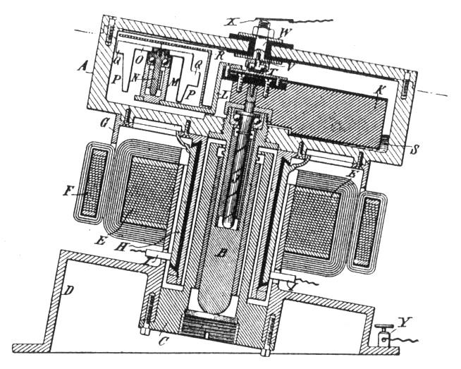
Referring to Fig. 2, the operative portions of the circuit-controlling mechanism are contained in a closed cylindrical receptacle A, of iron or steel, mounted on a spindle B in a suitable socket or support C to permit it to be freely and rapidly rotated. The socket C is secured to or forms a part of a base or stand D.
As a means of producing the proper rotation of the receptacle A, a field-magnet E is shown, mounted on or secured to the base D, and an armature F, supported by a bracket G from the under side of the receptacle A. The same bracket also carries a series of commutator-segments H, upon which bear brushes I, these parts being arranged to constitute an electromagnetic motor with stationary field and rotating armature. Any other suitable means, however, may be employed to rotate the receptacle and the fluid.
In the spindle B and concentric with its axis is a spindle J in bearings specially constructed to reduce friction in order that the spindle J may be as little as possible influenced by the rotation of the main spindle and receptacle which it carries. A suitable provision is made to oppose or prevent the rotation of the spindle J during the rotation of the receptacle. For this purpose the following has been devised.
The spindle B is held by its bearings at an angle to the vertical, and a weight K is secured eccentrically to the spindle J and tends to hold the spindle always in one position. The inclination of the axes of rotation necessary for this result may be as shown, and should not be greater, for the reason that it is especially advantageous to preserve the spindles and bearings as nearly as practicable vertical on account of lesser friction and easier lubrication.
Attached to the spindle J or weight K is an insulated bracket L, carrying a standard or socket M, in which is mounted on antifriction-bearings a spindle N. Secured to this latter is a plate with radial arms O, from which depend vanes or blades P, with projections Q extending radially from it. A shield or screen R incloses the vanes, except on the side adjacent to the inner periphery of the receptacle A.
A small quantity of a conducting fluid S is placed in the receptacle, and in order to secure a good electrical connection between the vanes P and a terminal on the outside of the receptacle a small mercury-cup T, in metallic contact with the vanes through the bracket L and socket M, is secured to the weight K. A metal stud V, set in an insulated bolt W, projects into the cup T through a packed opening in its cover. One terminal of the circuit-controlling mechanism will thus be any part of the metal receptacle and the other the insulated bolt W. The apparatus may be connected up in circuit by connecting the wires of the circuit to a brush X, bearing on the bolt W, and to a binding-post Y in contact with the base D.
To operate the apparatus, the receptacle is set in rotation, and as its speed increases the mercury or other conducting fluid which it contains is carried by centrifugal force up the sides of the inner wall, over which it spreads in a layer. When this layer rises sufficiently to encounter the projections Q on the blades or vanes P, the latter are set in rapid rotation, and the electrical connection between the terminal of the apparatus is thereby made and broken, it may be, with very great rapidity.
The projections Q are preferably placed at different heights on the vanes P, so as to secure greater certainty of good contact with the mercury film when in rapid rotation.
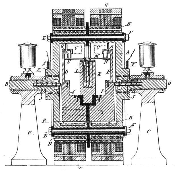
Fig. 3 is a central vertical cross-section of another type, which involves two salient features of novelty, one that it provides for maintaining in a rotating receptacle a stationary jet or jets which by impinging on a rigid conductor maintain the latter in rotation, thereby securing the requisite rapidly-intermittent contact between the two, and the other that it utilizes the rotation of such rigid conductor as a means for opposing or preventing the movement of its own supports in the direction of rotation of the receptacle, thereby securing, among other things, an approximately constant relative movement between the parts, a feature which in devices of this kind is often very desirable.
Referring to the figure, A designates a receptacle, usually of iron or steel and mounted in any suitable manner, as by trunnions B B, having bearings in standards C C, so as to be capable of rapid rotation about a horizontal axis.
The receptacle is divided into two parts insulated by a washer D and held together by insulated bolts E with nuts F. These two parts are electrically connected, respectively with the two terminals of the apparatus, and by means of brushes X Y, bearing at any suitable points on the two parts of the receptacle, the circuit-controller is connected with the wires of a circuit.
Any convenient means may be employed to rotate the receptacle; but a simple way to effect this is to surround the same with a field-magnet G and to make the receptacle itself the armature of an electric motor or else to secure to it armature-cores, as H.
A body I is supported by trunnions J, having bearings in the ends of the receptacle and concentric with the axis of rotation of the same. The weight of the body I being eccentric to this axis tends to oppose its turning about the axis when the receptacle is rotated.
Upon the body or support I, but insulated therefrom, is secured a vertical standard K, in which there is a freely-rotatable spindle L, carrying a disc M, with radial arms inclined to the plane of the disc, so as to form vanes N. Arms O P are also secured to the body I and are formed with or carry at their ends ducts or tubes Q, with one end directed toward and opening upon the vanes N, and the other end close to the inner wall of the receptacle and opening in the direction opposite to that of the rotation of the receptacle.
A suitable quantity of mercury R is placed in the receptacle before the latter is sealed or closed.
The operation of the device is as follows: The receptacle is started in rotation, and as it acquires a high velocity the mercury or other conducting fluid R is caused by centrifugal action to distribute itself in a layer over the inner peripheral surface of the receptacle. As the tubes or ducts Q do not take part in the rotation of the fluid, being held at the start by the weighted body I, they take up the mercury as soon as it is carried to the points where the ducts open and discharge it upon the vanes of the disc M. By this means the disc is set in rapid rotation, establishing the contact between the two sides of the receptacle which constitute the two terminals of the circuit-controller whenever the two streams or jets of fluid are simultaneously in contact with the vanes, but breaking the contact whenever the jets discharge through the spaces between the vanes. The chief object of employing more than one insulated jet is to secure a higher velocity of approach and separation. The disc M, having acquired a very rapid rotation, operates to prevent by gyrostatic action any tendency of the body I to rotate or oscillate, as such movement would change the plane of rotation of the disc. The movement of the parts, therefore, and the operation of the device as a whole are very steady and uniform, and a material practical advantage is thereby secured. The speed of the disc will be chiefly dependent on the velocity of the streams and pitch of the blades, and it is of course necessary in order to produce a constant speed of rotation of the disc that the velocity of the streams be constant. This is accomplished by rotating the receptacle with a constant speed; but when this is impracticable and the uniformity of motion of the disk very desirable special means are resorted to secure this result, as by providing overflowing-reservoirs V V, as indicated by dotted lines, from which the fluid issues upon the vanes with constant velocity, though the speed of the receptacle may vary between wide limits.
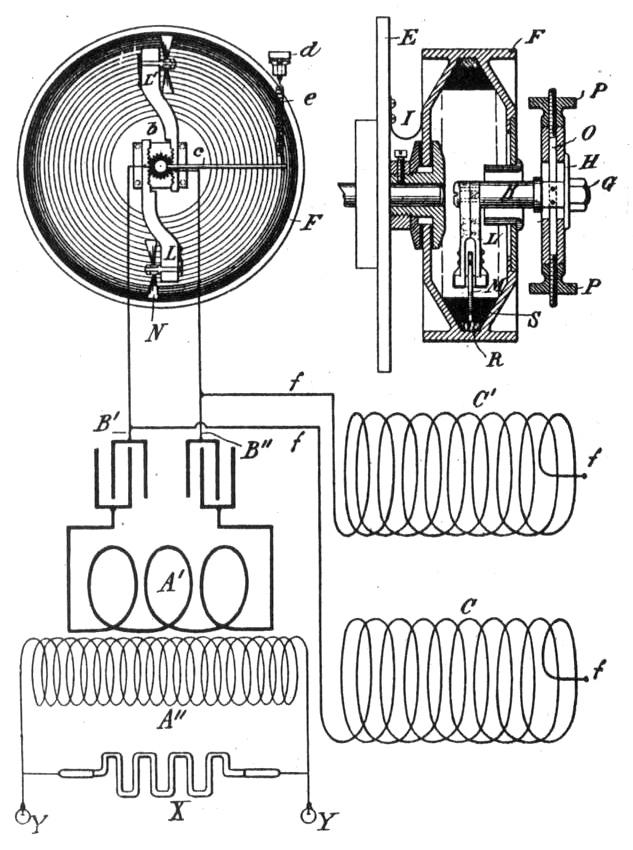
In Fig. 4 is shown a central vertical section of an improved circuit controller and Fig. 5 represents the latest and most preferred form, showing it in connection with the remaining parts of the apparatus illustrated diagrammatically. In these forms the receptacle contains both a conducting and a non-conducting fluid, the former being the heavier, and the terminals are maintained in such relations that the electrical connection between them is made and broken by the successive immersion of the contact-points into and their withdrawal from the conducting through the non-conducting fluid. These relations are best maintained by such construction of the receptacle that the distribution of the two fluids necessary for the proper operation of the device may be preserved by centrifugal action and the rotation of the other terminal effected by the movement of the fluids in relation to it.
To secure the conditions necessary for the accomplishment of the objects of the invention, various mechanical expedients may be resorted to; but the best and most practicable device for the purpose appeared to Mr. Tesla to be a hollow wheel or drum mounted so as to be rotated at any desired speed and containing a conducting fluid, such as mercury or an electrolyte, which by the rotation of the drum is thrown by centrifugal force outward to the inner periphery of the same, and a sufficient quantity of a lighter non-conducting or poorly-conductive fluid, such as water or oil, which by the centrifugal action is maintained on the surface of the heavier conducting fluid and tends to prevent the occurrence of arcs between the contact-points and the conducting fluid.
A central opening is formed in one side of the drum, through which enters an arm carrying a disc with peripheral projections or vanes which when the drum is rotated project to a sufficient extent toward or into the conducting fluid to effect the makes and breaks of the circuit.
The motion of the fluid within the drum causes the disc to rotate and its projections or vanes to make and break the circuit with a rapidity which may be very great. In fact, when the drum is rotated at a high rate of speed, the fluid conductor may become in its effect similar to a solid body, upon which the conducting disc rolls so that the conducting fluid might be dispensed with.
In order to insure the proper immersion of the projections into the fluid to compensate for wear and at the same time to secure a yielding pressure between the fluid and the disc, it is desirable to employ for the disc some form of spring connection or support which will exert a force tending to force it in contact with the fluid.
Referring to Fig. 4, the various parts are mounted on a base, which contains the condenser, and comprise a transformer with primary and secondary coils, one or more self-induction coils, a small electromagnetic motor D, and the circuit-controller, which is driven by the motor.
The shaft of the motor D extends through a stationary disc E, and to its end is keyed a hollow wheel or drum F, which rotates with it. Two standards G are secured to the disc E and connected by a cross-bar H, from which extends an arm K into the interior of the drum F through a central opening in its side.
To the end of the arm K is secured an arm L, carrying at its free end a disc M with peripheral teeth or projections N. The disc is mounted on any suitable bearings in the arm L, so as to be capable of free rotation.
It is desirable that the disc should admit of adjustment with respect to the inner peripheral surface of the drum, and for this purpose the arm K is secured to a rod O, which passes through supports in the cross-bar H and is adjustable therein by means of threaded nuts P.
The interior of the drum F is tapered or contracted toward the periphery so as to form a narrow trough in which the fluid is confined when the drum is rotated.
R designates the conducting fluid, and S the lighter nonconducting fluid, which are used in the drum. If the proper quantities and proportions of these fluids be introduced into the drum and the latter set in rapid rotation, the two fluids will distribute themselves under the action of centrifugal force around the drum in the manner shown in the figure. The arm K is adjusted so that the teeth or projections on the disc M will just enter the conducting fluid, and by the action of either or both the disc will be rapidly rotated. Its teeth are so arranged that no two are simultaneously in contact with the conducting fluid, but come into the same successively. If, therefore, one part of the circuit be connected to the drum, as by a contact strip or brush T, and the other part to the disc M, or to any part, as the standards G, which are insulated from the frame of the apparatus and in metallic connection with the disc M, the circuit will be made and broken with a rapidity which may obviously be made enormously high. The presence of the non-conducting fluid on the surface of the other operates to prevent the occurrence of sparks as the teeth N leave the latter and also to prevent the current from leaping across the space between the teeth and the conductor as the two approach.
The diagram of circuit connections shown in Fig. 5 will serve to illustrate the purpose and mode of operation of the latest device. Let f f be the conductors from a source of current, each including a self-induction coil C C' and connected with the arms L and L' and with two conductors B' B", respectively. Then during the periods when the circuit is completed between the two arms L L' the coils C C' store energy, which on the interruption of said circuit rushes into and charges the condensers. These latter during the periods when the circuit is closed between arms L and L' discharge through the primary A' and induce by such discharge currents in the secondary A", which are utilized for any purpose for which they may be suited, as in operating vacuum-tubes X or suitable lamps Y. It will be understood that the rotating drum may be mounted in a horizontal or other plane.