Nikola Tesla Articles
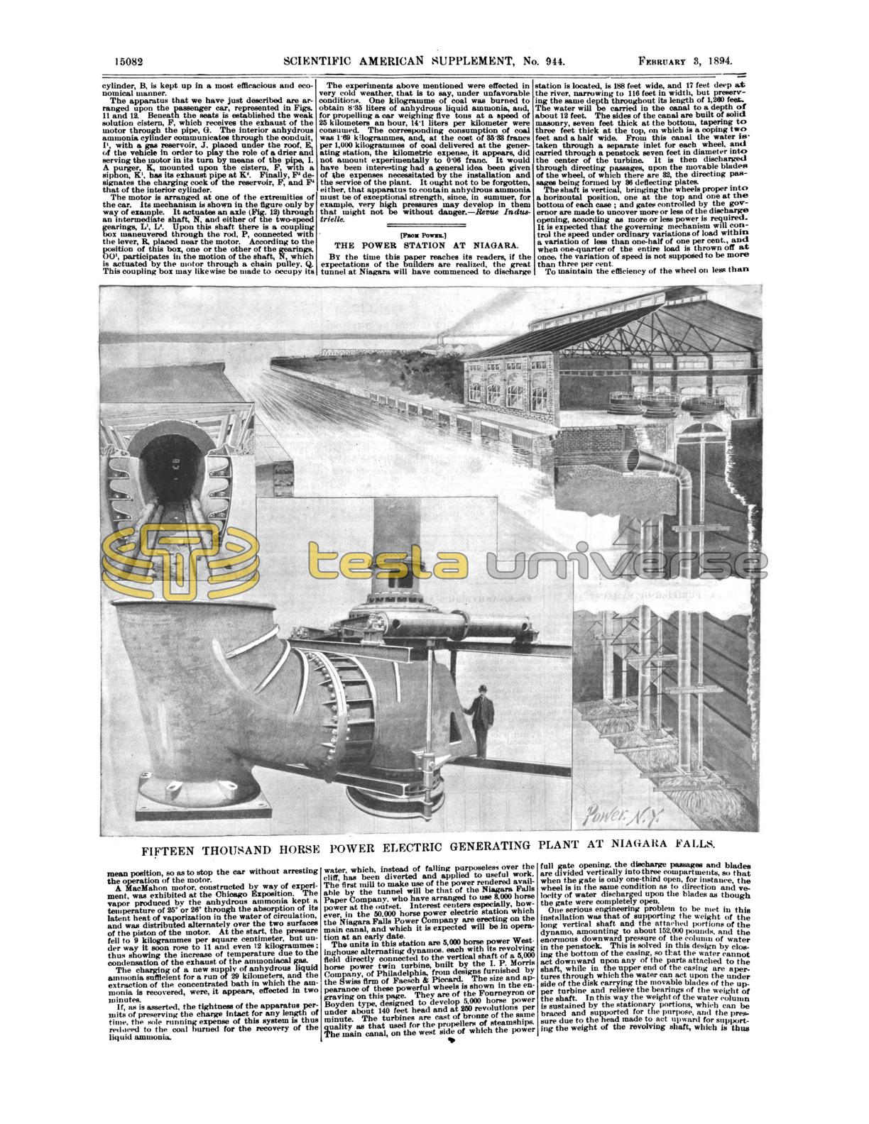
The Power Station at Niagara
By the time this paper reaches its readers, if the expectations of the builders are realized, the great tunnel at Niagara will have commenced to discharge water, which, instead of falling purposeless over the cliff, has been diverted and applied to useful work. The first mill to make use of the power rendered available by the tunnel will be that of the Niagara Falls Paper Company, who have arranged to use 8,000 horse power at the outset. Interest centers especially, however, in the 50,000 horse power electric station which the Niagara Falls Power Company are erecting on the main canal, and which it is expected will be in operation at an early date.
The units in this station are 5,000 horse power Westinghouse alternating dynamos, each with its revolving field directly connected to the vertical shaft of a 5,000 horse power twin turbine, built by the I. P. Morris Company, of Philadelphia, from designs furnished by the Swiss firm of Faesch & Piccard. The size and appearance of these powerful wheels is shown in the engraving on this page. They are of the Fonrneyron or Boyden type, designed to develop 5,000 horse power under about 140 feet head and at 250 revolutions per minute. The turbines are cast of bronze of the same quality as that used for the propellers of steamships. The main canal, on the west side of which the power station is located, is 188 feet wide, and 17 feet deep at the river, narrowing to 116 feet in width, but preserving the same depth throughout its length of 1,260 feet. The water will be carried in the canal to a depth of about 12 feet. The sides of the canal are built of solid, masonry, seven feet thick at the bottom, tapering to three feet thick at the top, on which is a coping two feet and a half wide. From this canal the water is taken through a separate inlet for each wheel, and carried through a penstock seven feet in diameter into the center of the turbine. It is then discharged through directing passages, upon the movable blades of the wheel, of which there are 32, the directing passages being formed by 36 deflecting plates.
The shaft is vertical, bringing the wheels proper into a horizontal position, one at the top and one at the bottom of each case; and gates controlled by the governor are made to uncover more or less of the discharge opening, according as more or less power is required. It is expected that the governing mechanism will control the speed under ordinary variations of load within a variation of less than one-half of one per cent., and when one-quarter of the entire load is thrown off at once, the variation of speed is not supposed to be more than three per cent.
To maintain the efficiency of the wheel on less than full gate opening, the discharge passages and blades are divided vertically into three compartments, so that when the gate is only one-third open, for instance, the wheel is in the same condition as to direction and velocity of water discharged upon the blades as though the gate were completely open.
One serious engineering problem to be met in this installation was that of supporting the weight of the long vertical shaft and the attached portions of the dynamo, amounting to about 152,000 pounds, and the enormous downward pressure of the column of water in the penstock. This is solved in this design by closing the bottom of the casing, so that the water cannot act downward upon any of the parts attached to the shaft, while in the upper end of the casing are apertures through which the water can act upon the under side of the disk carrying the movable blades of the upper turbine and relieve the bearings of the weight of the shaft. In this way the weight of the water column is sustained by the stationary portions, which can be braced and supported for the purpose, and the pressure due to the head made to act upward for supporting the weight of the revolving shaft, which is thus nearly in the condition of a shaft spinning upon the water. The area involved is so proportioned that when the wheels are lightly loaded the upward pressure will be some 2,000 pounds in excess of the weight of the shaft, and when the wheels are running at full gate about the same amount less than the weight of the shaft, on account of the lesser pressure in the casing. This variation in pressure and direction is taken care of by a thrust bearing shown in section in the detail drawings.
The shaft consists of a steel shell about a foot in diameter, with smaller solid portions in the journals, which require to be of less frequency on account of the stiffness due to the large diameter of the hollow shaft. The latter is of rolled steel tubing, without any visible vertical seam. No flywheel is required, sufficient momentum and inertia being furnished by the heavy fields of the dynamo which are carried upon the shaft.
The dynamos are constructed upon the two-phase alternating current system, with stationary armature and revolving fields, and are designed to generate a potential of 2,000 to 2,400 volts, which will be increased or diminished by step-up or step-down transformers for transmission or local use. Motor generators will be run for the production of continuous current when required, so that the station will be able to furnish continuous or alternating current of any potential. Two-phase Tesla motors will be used. The station is designed eventually to comprise ten of the units described, and the wheel pit and building will be extended toward the river and new wheels put in as required. Meantime power from the station itself will be available for carrying on the work, extending the wheel pit and the main tunnel, and the many mechanical operations connected with grading and inaugurating the industrial city which will grow up about this source of cheap and continuous power.
The power house is being built of stone, with a steel frame, and lined with enameled brick. The steel roof of trusses of over 60 feet span rests upon steel posts that serve to carry the girders to sustain a 50 ton traveling crane which commands the entire floor. At the north end of the house the width will be greatly increased, and an L added, extending eastward to the edge of the canal. This L and the enlarged extension of the main building will form the entrance front and will present gable ends to the east and west. To the left of the entrance archway the offices, four stories in height, will be located, wholly in the L, while to the right, including the archway, the whole height of the power house to which it is attached consists of one large room, all accessible to the traveling crane. An arched portal or main doorway of great height forms the entrance vestibule, through which cars loaded to the limit of railway regulation can readily pass into the main power house, through a second lower arch-way, which in summer will be closed with iron grill work and in winter by doors. Above this second arch will be a medallion of the Indian Chief Ni-a-ga-ra, standing in his canoe shooting the rapids, which has been adopted as the seal of the company. The entrance to the offices is in the left wall of the vestibule, and gives access also to visitors, who, passing a ticket office, gain by an easy flight of stairs a bridge that crosses the great end room of the power station, from which the whole interior may be seen. In this large room will be located the switchboard and testing instruments.
The distribution will be through underground conduits extending in various directions from the station to the principal points of service. A photograph of the conduit in course of construction is shown in the upper left hand panel of the engraving on the opposite page. The conductors will be carried on insulated brackets on both sides. A track extends throughout the length of the conduit, upon which an electrically propelled car will carry the linemen between wire screens that protect them from the dangerous currents through which they pass and allow every portion of the line, brightly illuminated by the passing car, to be thoroughly inspected with absolute safety. The brackets are located 30 feet apart. The concrete casing is made of three parts gravel and one part Portland cement.
One of the largest and earliest consumers of power from this station will be the Pittsburg Reduction Company, whose plant will be located about 2,500 feet from the power house. They will use a current equivalent to about 3,000 horse power in the reduction of aluminum, and light and power will be furnished as fast as the generating and transmitting plant can be put down, not only to the factories which will be erected upon the surrounding land, but to Buffalo and the surrounding country. Experiments are being made to determine the practicability of its use in propelling the boats on the Erie canal. Electricity is the method most in favor for distribution, although Professor Unwin, who is identified with the work, says that power can be transmitted by compressed air to a distance of 30 miles in a 30 inch main, with an efficiency of from 59 to 73 per cent. if reheated, and 40 to 50 per cent. if used cold. In blocks of 500 horse power or less motors will be used. Groups of wheels arranged in sets of five to each pit will be arranged to give power in blocks of 1,000 horse power to a single manufactory, or to several establishments that can combine to use that unit. The cost of excavating the deep wheel pits makes smaller units impracticable by direct wheels, but more efficiently supplied by electricity from the large generators through which a multiplicity of small powers may be grouped upon one large wheel.