Nikola Tesla Books
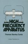

214 B Fig.1 8" HIGH FREQUENCY APPARATUS B Core irons 3Ã8" 340 pcs 3'-6' 340 pcs Core of silicon steel.or7" thick. Fig. 2 To spool Fig 3 Core leg taped ready for winding To spool Fig.4 Fig. 5 Showing method of building up core irons Copper ribbon Starting end of wire soldered and successive turns wound over ribbon Fig.6 To spool Ribbon to which finishing end is soldered Primary wound and faped ready for secondary Fig. 7 When 45 th. turn is wound Finishing ends soldered. Fig.8 Fig.9 Starting ends soldered wound a wires in multiple. solder to ribbon before finishing winding. One leg with primary and secondary finished Figs. 1 to 9 inclusive.-Details of the welding transformer that 90 turns may be used if desired. The winding is of No. 9 D.C.C. magnet wire in four layers of 30 turns per layer. Two layers are wound on each leg. With reference to Fig. 5, the winding is started by soldering the end of the wire from the spool to the end of a piece of stout copper ribbon which is then insulated with a layer of paper and the winding continued over it for one layer. This prevents the annoyance of the first turn coming loose after the winding is removed from the lathe. Over the first layer of the primary is placed a layer of press board and then the second layer of wire is wound until the 45th turn is reached. At this point a tap of copper ribbon is taken as shown in Fig. 7. Over this the windin place. This turn ing is continued until the 90th turn is is soldered to the tip of a third piece of ribbon previously placed so that the winding holds it. The same procedure
