Nikola Tesla Lectures
A New System of Alternate Current Motors and Transformers
American Institute of Electrical Engineers, May 16, 1888
I desire to express my thanks to Professor Anthony for the help he has given me in this matter. I would also like to express my thanks to Mr. Pope and Mr. Martin for their aid. The notice was rather short, and I have not been able to treat the subject so extensively as I could have desired, my health not being in the best condition at present. I ask your kind indulgence, and I shall be very much gratified if the little I have done meets your approval.
In the presence of the existing diversity of opinion regarding the relative merits of the alternate and continuous current systems, great importance is attached to the question whether alternate currents can be successfully utilized in the operation of motors. The transformers, with their numerous advantages, have afforded us a relatively perfect system of distribution, and although, as in all branches of the art, many improvements are desirable, comparatively little remains to be done in this direction. The transmission of power, on.the contrary, has been almost entirely confined to the use of continuous currents, and notwithstanding that many efforts have been made to utilize alternate currents for this purpose, they have, up to the present, at least as far as known, failed to give the result desired. Of the various motors adapted to be used, on alternate current circuits the following have been mentioned: 1. A series motor with subdivided field. 2. An alternate current generator having its field excited by continuous currents. 3. Elihu Thomson's motor. 4. A combined alternate and continuous current motor. Two more motors of this kind have suggested themselves to me. 1. A motor with one of its circuits in series with a transformer and the other in the secondary of the transformer. 2. A motor having its armature circuit connected to the generator and the field coils closed upon themselves. These, however, I mention only incidentally.
The subject which I now have the pleasure of bringing to your notice is a novel system of electric distribution and transmission of power by means of alternate currents, affording peculiar advantages, particularly in the way of motors, which I am confident will at once establish the superior adaptability of these currents to the transmission of power and will show that many results heretofore unattainable can be reached by their use; results which are very much desired in the practical operation of such systems and which cannot be accomplished by means of continuous currents.
Before going into a detailed description of this system, I think it necessary to make a few remarks with reference to certain conditions existing in continuous current generators and motors, which, although generally known, are frequently disregarded.
In our dynamo machines, it is well known, we generate alternate currents which we direct by means of a commutator, a complicated device and, it may be justly said, the source of most of the troubles experienced in the operation of the machines. Now, the currents so directed cannot be utilized in the motor, but they must — again by means of a similar unreliable device — be reconverted into their original state of alternate currents. The function of the commutator is entirely external, and in no way dues it affect the internal working of the machines. In reality, therefore, all machines ace alternate current machines, the currents appearing as continuous only in the external circuit during their transit from generator to motor. In view simply of this fact, alternate currents would commend themselves as a more direct application of electrical energy, and the employment of continuous currents would only be justified if we had dynamos which would primarily generate, and motors which would be directly actuated by such currents.
But the operation of the commutator on a motor is twofold; firstly, it reverses the currents through the motor, and secondly, it effects, automatically, a progressive shifting of the poles of one of its magnetic constituents. Assuming, therefore, that both of the useless operations in the system, that is to say, the directing of the alternate currents on the generator and reversing the direct currents on the motor, be eliminated, it would still be necessary, in order to cause a rotation of the motor, to produce a progressive shifting of the poles of one of its elements, and the question presented itself, — How to perform this operation by the direct action of alternate currents? I will now proceed to show how this result was accomplished.
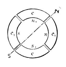
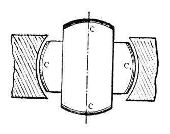
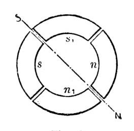
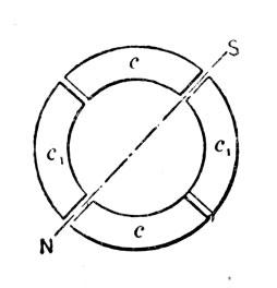
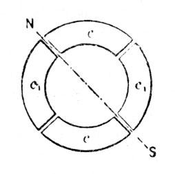
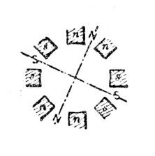
In the first experiment a drum-armature was provided with two coils at right angles to each other, and the ends of these coils were connected to two pairs of insulated contact-rings as usual. A ring was then made of thin insulated plates of sheet-iron and wound with four coils, each two opposite coils being connected together so as to produce free poles on diametrically opposite sides of the ring. The remaining free ends of the coils were then connected to the contact-rings of the generator armature so as to form two independent circuits, as indicated in figure 9. It may now be seen what results were secured in this combination, and with this view I would refer to the diagrams, figures 1 to 8a. The field of the generator being independently excited, the rotation of, the armature sets up currents in the coils C C, varying in strength and direction in the well-known manner. In the position shown in figure 1 the current in coil C is nil while coil C1 is traversed by its maximum current, and the connections my be such that the ring is magnetized by the coils c1 c1 as indicated by the letters N S in figure 1a, the magnetizing effect of the coils c c being nil, since these coils are included in the circuit of coil C.
In figure 2 the armature coils are shown in a more advanced position, one-eighth of one revolution being completed. Figure 2a illustrates the corresponding magnetic condition of the ring. At this moment the coil cl generates a current of the same direction as previously, but weaker, producing the poles n1 s1 upon the ring; the coil c also generates a current of the same direction, and the connections may be such that the coils c c produce the poles n s, as shown in figure 2a. The resulting polarity is indicated by the letters N S, and it will be observed that the poles of the ring have been shifted one-eighth of the periphery of the same:
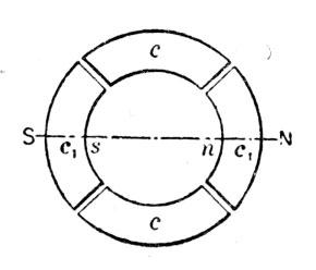
In figure 3 the armature has completed one-quarter of one revolution. In this phase the current in coil C is maximum, and of such direction as to produce the poles N S in figure 3a, whereas the current in coil C1 is nil, this coil being at its neutral position. The poles N S in figure 3a are thus shifted one-quarter of the circumference of the ring.
Figure 4 shows the coils C C in a still more advanced position, the armature having completed three-eighths of one revolution. At that moment the coil C still generates a current of the same direction as before, but of less strength, producing the comparatively weaker poles n sin figure 4a. The current in the coil C1 is of the same strength, but of opposite direction. Its effect is, therefore, to produce upon the ring the poles n1 and s1 as indicated, and a polarity, N S, results, the poles now being shifted three-eighths of the periphery of the ring.
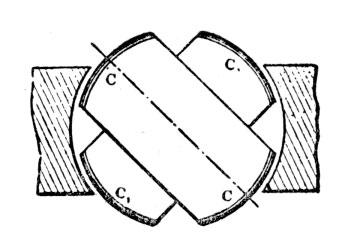
In figure 5 one-half of one revolution of the armature is completed, and the resulting magnetic condition of the ring is indicated in figure 5a. Now, the current in coil C is nil, while the coil C1 yields its maximum current, which is of the same direction as previously; the magnetizing effect is, therefore, due to the coils c1 c1 alone, and, referring to figure 5a, it will be observed that the poles N S are shifted one-half of the circumference of the ring. During the next half revolution the operations are repeated, as represented in the figures 6 to 8a.
A reference to the diagrams will make it clear that during one revolution of the armature the poles of the ring are shifted once around its periphery, and each revolution producing like effects, a rapid whirling of the poles in harmony with the rotation of the armature is the result. If the connections of either one of the circuits in the ring are reversed, the shifting of the poles is made to progress in the opposite direction, but the operation is identically the same. Instead of using four wires, with like result, three wires may be used, one forming a common return for both circuits.
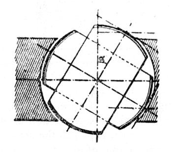
This rotation or whirling of the poles manifests itself in a series of curious phenomena. If a delicately pivoted disc of steel or other magnetic metal is approached to the ring it is set in rapid rotation, the direction of rotation varying with the position of the disc. For instance, noting the direction outside of the ring it will be found that inside the ring it turns in an opposite direction, while it is unaffected if placed in a position symmetrical to the ring. This is easily explained. Each time that a pole approaches it induces an opposite pole in the nearest point on the disc, and an attraction is produced upon that point; owing to this, as the pole is shifted further away from ;he disc a tangential pull is exerted upon the same, and the action being constantly repeated, a more or less rapid rotation of the disc is the result. As the pull is exerted mainly upon that part which is nearest to the ring, the rotation outside and inside, or right and left, respectively, is in opposite directions, figure 9. When placed symmetrically to the ring, the pull on opposite sides of the disc being equal, no rotation results. The action is based on the magnetic inertia of the iron; for this reason a disc of hard steel is much more affected than a disc of soft iron, the latter being capable of very rapid variations of magnetism. Such a disc has proved to be a very useful instrument in all these investigations, as it has enabled me to detect any irregularity in the action. A curious effect is also produced upon iron filings. By placing some upon a paper and holding them externally quite close to the ring they are set in a vibrating motion, remaining in the same place, although the paper may be moved back and forth; but in lifting the paper to a certain height which seems to be dependent on the intensity of the poles and the speed of rotation, they are thrown away in a direction always opposite to the supposed movement of the poles. If a paper with filings is put flat upon the ring and the current turned on suddenly, the existence of a magnetic whirl may be easily observed.
To demonstrate the complete analogy between the ring and a revolving magnet, a strongly energized electro-magnet was rotated by mechanical power, and phenomena identical in every particular to those mentioned above were observed.
Obviously, the rotation of the poles produces corresponding inductive effects and may be utilized to generate currents in a closed conductor placed within the influence of the poles. For this purpose it is convenient to wind a ring with two sets of superimposed coils forming respectively the primary and secondary circuits, as shown in figure 10. In order to secure the most economical results the magnetic circuit should be completely closed, and with this object in view the construction may be modified at will.
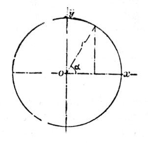
The inductive effect exerted upon the secondary coils will be mainly due to the shifting or movement of the magnetic action; but there may also be currents set up in the circuits in consequence of the variations in the intensity of the poles. However, by properly designing the generator and determining the magnetizing effect of the primary calls the latter element may be made to disappear. The intensity of the poles being maintained constant, the action of the apparatus will be perfect, and the same result will be secured as though the shifting were effected by means of a commutator with an infinite number of bars. In such case the theoretical relation between the energizing effect of each set of primary coils .and their resultant magnetizing effect may be expressed by the equation of a circle having its centre coinciding with that of an orthogonal system of axes, and in which the radius represents the resultant and the co-ordinates both of its components. These are then respectively the sine and cosine of the angle a between the radius and one of the axes (O X). Referring to figure 1 I, we have r2= x2 + y2; where x = r cos a, and y = r sin a.
Assuming the magnetizing effect of each set of coils in the transformer to be proportional to the current — which may be admitted for weak degrees of magnetization — then x = Kc and y = Kc1, where K is a constant and c and c1 the current in both sets of coils respectively. Supposing, further, the field of the generator to be uniform, we have for constant speed c1 = K1 sin a and c = K1 sin (90° + a) = K1 cos a, where K1 is a constant. See figure 12.
Therefore, x = Kc = K K1 cos a;
y = Kc1= K K1 sin a, and
K K1 = r.
That is, for a uniform field the disposition of the two coils at right angles will secure the theoretical result, and the intensity of the shifting poles will be constant. But from r2 = x2 + y2 it follows that for y = 0, r = x; it follows that the joint magnetizing effect of both sets of coils should be equal to the effect of one set when at its maximum action. In transformers and in a certain class of motors the fluctuation of the poles is not of great importance, but in another class of these motors it is desirable to obtain the theoretical result.
In applying this principle to the construction of motors, two typical forms of motor have been developed. First, a form having a comparatively small rotary effort at the start, but maintaining a perfectly uniform speed at all loads, which motor has been termed synchronous. Second, a form possessing a great rotary effort at the start, the speed being dependent on the load.
These motors may be operated in three different ways: 1. By the alternate currents of the source only. 2. By a combined action of these and of induced currents. 3. By the joint action of alternate and continuous currents.
The simplest form of a synchronous motor is obtained by winding a laminated ring provided with pole projections with four coils, and connecting the same in the manner before indicated. An iron disc having a segment cut away on each side may be used as an armature. Such a motor is shown in figure 9. The disc being arranged to rotate freely within the ring in close proximity to the projections, it is evident that as the poles are shifted it will, owing to its tendency to place itself in such a position as to embrace the greatest number of the lines of force, closely follow the movement of the poles, and its motion will be synchronous with that of the armature of the generator; that is, in the peculiar disposition shown in figure 9, in which the armature produces by one revolution two current impulses in each of the circuits. It is evident that if, by one revolution of the armature, a greater number of impulses is produced, the speed of the motor will be correspondingly increased. Considering that the attraction exerted upon the disc is greatest when the same is in close proximity to the poles, it follows that such a motor will maintain exactly the same speed at all loads within the limits of its capacity.
To facilitate the starting, the disc may be provided with a coil closed upon itself. The advantage secured by such a coil is evident. On the start the currents set up in the coil strongly energize the disc and increase the attraction exerted upon the same by the ring, and currents being generated in the coil as long as the speed of the armature is inferior to that of the poles, considerable work may be performed by such a motor even if the speed be below normal. The intensity of the poles being constant, no currents will be generated in the coil when the motor is turning at its normal speed.
Instead of closing the coil upon itself, its ends may be connected to two insulated sliding rings, and a continuous current supplied to these from a suitable generator. The proper way to start such a motor is to close the coil upon itself until the normal speed is reached, or nearly so, and then turn on the continuous current. If the disc be very strongly energized by a continuous current the motor may not be able to start, but if it be weakly energized, or generally so that the magnetizing effect of the ring is preponderating it will start and reach the normal speed. Such a motor will maintain absolutely the same speed at all loads. It has also been found that if the motive power of the generator is not excessive, by checking the motor the speed of the generator is diminished in synchronism with that of the motor. It is characteristic of this form of motor that it cannot be reversed by reversing the continuous current through the coil.
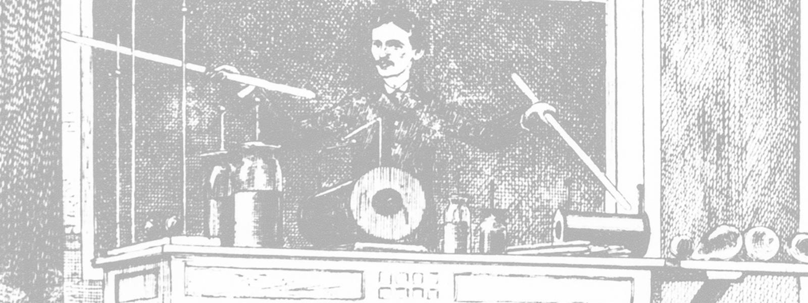
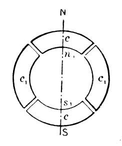
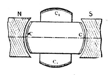
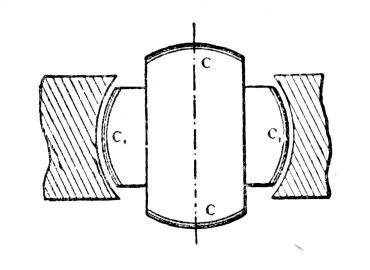
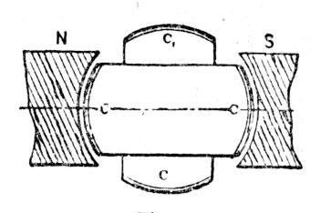
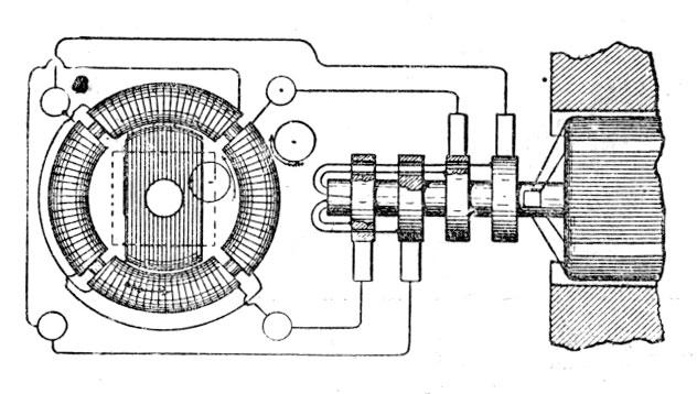
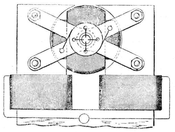
The synchronism of these motors may be demonstrated experimentally in a variety of ways. For this purpose it is best to employ a motor' consisting of a stationary field magnet and an armature arranged to rotate within the same, as indicated in figure 13. In this case the shifting of the poles of the armature produces a rotation of the latter in the opposite direction. It results therefrom that when the normal speed is reached, the poles of the armature assume fixed positions relatively to the field magnet and the same is magnetized by induction, exhibiting a distinct pole on each of the pole-pieces. If a piece of soft iron is approached to the field magnet it will at the start be attracted with a rapid vibrating motion produced by the reversals of polarity of the' magnet, but as the speed of the armature increases, the vibrations become less and less frequent and finally entirely cease. Then the iron is weakly but permanently attracted, showing that the synchronism is reached and the field magnet energized by induction.
The disc may also be used for the experiment. If held quite close .to the armature it will turn as long as the speed of rotation of the poles exceeds that of the armature; but when the normal speed is reached, or very nearly so, it ceases to rotate and is permanently attracted.
A crude but illustrative experiment is made with an incandescent lamp. Placing the lamp in circuit with the continuous current generator, and in series with the magnet coil, rapid fluctuations are observed in the light in consequence of the induced currents set up in the coil at the start; the speed increasing, the fluctuations occur at longer intervals, until they entirely disappear, showing that the motor has attained its normal speed.
A telephone receiver affords a most sensitive instrument; when connected to any circuit in the motor the synchronism may be easily detected on the disappearance of the induced currents.
In motors of the synchronous type it is desirable to .maintain the quantity of the shifting magnetism constant, especially if the magnets are not properly subdivided.
To obtain a rotary effort in these motors was the subject of long thought. In order to secure this result it was necessary to make such a disposition that while the poles of one element of the motor are shifted by the alternate currents of the source, the poles produced upon the other element should always be maintained in the proper relation to the former, irrespective of the speed of the motor. Such a condition exists in a continuous current motor; but in a synchronous motor, such as described, this condition is fulfilled only when the speed is normal.
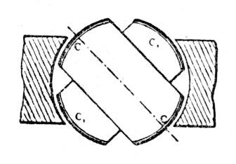
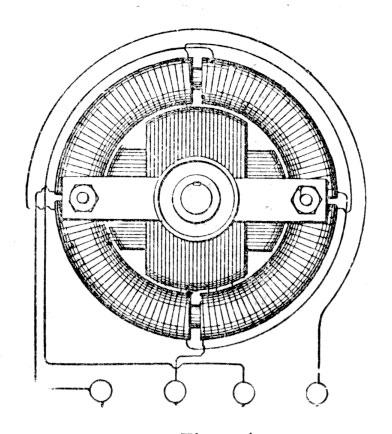
The object has been attained by placing within the ring a properly subdivided cylindrical iron core wound with several independent coils closed upon themselves. Two coils at right angles as in figure 14, are sufficient, but a greater number may be advantageously employed. It results from this disposition that when the poles of the ring are shifted, currents are generated in the closed armature coils. These currents are the most intense at or near the points of the greatest density of the lines of force, and their effect is to produce poles upon the armature at right angles to those of the ring, at least theoretically so; and since action is entirely independent of the speed — that is, as far as the location of the poles is concerned — a continuous pull is exerted upon the periphery of the armature. In many respects these motors are similar to the continuous current motors. If load is put on, dig speed, and also the resistance of the motor, is diminished and more current is made to pass through the energizing coils, thus increasing the effort. Upon the load being taken off, the counter-electromotive force increases and less current passes through the primary or energizing coils. Without any load the speed is very nearly equal to that of the shifting poles of the field magnet.
It will be found that the rotary effort in these motors fully equals that of the continuous current motors. The effort seems to be greatest when both armature and field magnet are without any projections; but as in such dispositions the field cannot be very concentrated, probably the best results will be obtained by leaving pole projections on one of the elements only. Generally, it may be stated that the projections diminish the torque and produce a tendency to synchronism.
A characteristic feature of motors of this kind is their capacity of being very rapidly reversed. This follows from the peculiar action of the motor. Suppose the armature to be rotating and the direction of rotation of the poles to be reversed. The apparatus then represents a dynamo machine, the power to drive this machine being the momentum stored up in the armature and its speed being the sum of the speeds of the armature and the poles. If we now consider that the power to drive such a dynamo would be very nearly proportional to the third power of the speed, for this reason alone the armature should be quickly reversed. But simultaneously with the reversal another element is brought into action, namely, as the movement of the poles with respect to the armature is reversed, the motor acts like a transformer in which the resistance of the secondary circuit would be abnormally diminished by producing in this circuit an additional electromotive force. Owing to these causes the reversal is instantaneous.
If it is desirable to secure a constant speed, and at the same time a certain effort at the start, this result may be easily attained in a variety of ways. For instance, two armatures, "one for torque and the other for synchronism, may be fastened on the same shaft, ,and any desired preponderance may be given to either one, or an armature may be wound for rotary effort, but a more or less pronounced tendency to synchronism may be given to it by properly constructing the iron core; and in many other ways.
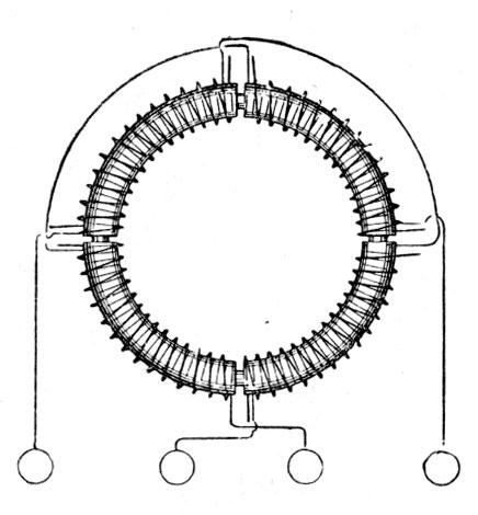
As a means of obtaining the required phase of the currents in both the circuits, the disposition of the two coils at right angles is the simplest, securing the most uniform action; but the phase may be obtained in many, other ways,.. varying with the machine employed. Any of the dynamos at present in use may be easily adapted for this purpose by making connections to proper points of the generating coils. In closed circuit armatures, such as used in the continuous current systems, it is best to make four derivations from equi-distant points or bars of the commutator, and to connect the same to four insulated sliding rings on the shaft. In this case each of the motor circuits is connected to two diametrically opposite bars of the commutator. In such a disposition the motor may also be operated at half the potential and on the three-wire plan, by connecting the motor circuits in the proper. order to three of the contact rings.
In multipolar dynamo machines, such as used in the converter systems, the phase is conveniently obtained by winding upon the armature two series of coils in such a manner that while the coils of one set or series are at their maximum production of current; the coils of the other will be at their neutral position, or nearly so, whereby both sets of coils may be subjected simultaneously or successively to the inducing action of the field magnets.
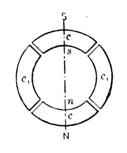
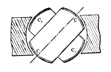
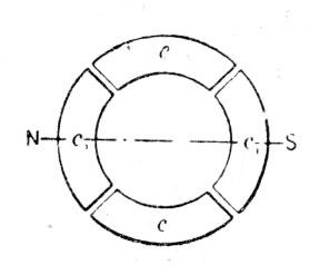
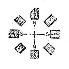
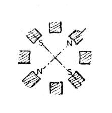
Generally the circuits .in the motor will be similarly disposed, and various arrangements may be made to fulfill the requirements; but the simplest and most practicable is to arrange primary circuits on stationary parts of the motor, thereby obviating, at least in certain forms, the employment of sliding contacts. In such a case the magnet coils are connected alternately in both the circuits; that is 1, 3, 5 … in one, and 2, 4, 6 … in the other, and the coils of each set of series may be connected all in the same manner, or alternately in opposition; in the latter case a motor with half the number of poles will result, and its action will be correspondingly modified. The figures 15, 16 and 17, show three different phases, the magnet coils in each circuit being connected alternately in opposition. In this case there will be always four poles, as in figures 15 and 17, four pole projections will be neutral, and in figure 16 too adjacent pole projections will have the same polarity. If the coils are connected in the same manner there will be eight alternating poles, as indicated by the letters n's' in fig. 15.
The employment of multipolar motors secures in this system an advantage much desired and unattainable in the continuous current system, and that is, that a motor may be made to run exactly at a predetermined speed irrespective of imperfections in construction, of the load, and, within certain limits, of electromotive force and current strength.
In a general distribution system of this kind the following plan should be adopted. At the central station of supply a generator should be provided having a considerable number of poles. The motors operated from this generator should be of the synchronous type, but possessing sufficient rotary effort to insure their starting. With the observance of proper rules of construction it may be admitted that the speed of each motor will be in some inverse proportion to its size, and the number of poles should be chosen accordingly. Still exceptional demands may modify this rule. In view of this, it will be advantageous to provide each motor with a greater number of pole projections or coils, the number being preferably a multiple of two and three. By this means, by simply changing the connections of the coils, the motor may be adapted to any probable demands.

If the number of the poles in the motor is even, the action will be harmonious and the proper result will be obtained; if this is not the case the best plan to be followed is to make a motor with a double number of poles ,and connect the same in the manner before indicated, so that half the number of poles result. Suppose, for instance, that the generator has twelve poles, and it would be desired to obtain a speed equal to 12/7 of the speed of the generator. This would require a motor with seven pole projections or magnets, and such a motor could not be properly connected in the circuits unless fourteen armature coils would be provided, which would necessitate the employment or sliding contacts. To avoid this the motor should be provided with fourteen magnets and seven connected in each circuit, the magnets in each circuit alternating among themselves: The armature should have fourteen closed coils. The action of the motor will not be quite as perfect as in .the case of an even number of poles, but the drawback will not be of a serious nature.
However, the disadvantages resulting from this unsymmetrical form will be reduced in the same proportion as the number of the poles is augmented.
If the generator has, say, n, and the motor n1 poles, the speed of the motor will be equal to that of the generator multiplied by n/n1
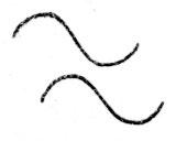
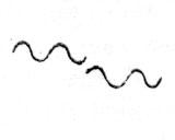
The speed of the motor will generally be dependent on the number of the poles, but there may be exceptions to this rule. The speed may be modified by the phase of the currents in the circuits or by the character of the current impulses or by intervals between each or between groups of impulses. Some of the possible cases are indicated in the diagrams, figures 18, 19, 20 and 21 which are self-explanatory. Figure 18 represents the condition generally existing, and which secures the best result. In such a case, if the typical form of motor illustrated in figure 9 is employed, one complete wave in each circuit will produce one revolution of the motor. In figure 19 the same result will he effected by one wave in each circuit, the impulses being successive; in figure 20 by four, and in figure 21 by eight waves.
By such means any desired speed may be attained; that is, at least within the limits of practical demands. This system possesses this advantage besides others, resulting from simplicity. At full loads the motors show an efficiency fully equal to that of the continuous current motors. The transformers present an additional advantage in their capability of operating motors. They are capable of similar modifications in construction, and will facilitate the introduction of motors and their adaptation to practical demands, Their efficiency should be higher than that of the present transformers, and I base my assertion on the following:
In a transformer as constructed at present we produce the currents in the secondary circuit by varying the strength of the primary or exciting currents. If we admit proportionality with respect to the iron core the inductive effect exerted upon the secondary coil will be proportional to the numerical sum of the variations in the strength of the exciting current per unit of time; whence it follows that for a given variation any prolongation of the primary current will result in a proportional loss. In order to obtain rapid variations in the strength of the current, essential to efficient induction, a great number of undulations are employed. From this practice various disadvantages result. These are, increased cost and diminished efficiency of the generator, more waste of energy in heating the cores, and also diminished output of the transformer, since the core is not properly utilized, the reversals being too rapid. The inductive effect is also very small in certain phases, as will be apparent from a graphic representation, and there may be periods of inaction, if there are intervals between the succeeding current impulses or waves. In producing a shifting of the poles in the transformer, and thereby inducing currents, the induction is of the ideal character, being always maintained at its maximum action. It is also reasonable to assume that by a shifting of the poles less energy will be wasted than by reversals.
DISCUSSION
Mr. Martin — Professor Anthony, I believe, is here, and as he has given this subject some attention, I think he might very properly supplement Mr. Testa's paper by some remarks.
Mr. Tesla — I want to express once more my best thanks to Professor Anthony for aiding me in many respects, and I hope he will be able to explain many of the features in this system that I was unable to explain at present.
Professor Anthony — Mr. President and Gentlemen: I have been referred to as having had something to do with these forms of motors. I am very glad to be able to add my testimony to what Mr. Testa has already given you in regard to their action, and I confess that on first seeing the motors the action seemed to me an exceedingly remarkable one. After my first visit to Mr. Tesla's works, some of the motors; I think these very two that you see here on the table, were brought to me to make some tests of their efficiency, and probably you will be more interested in those than in anything else that I might say. I am sorry I have not brought with me the exact figures that we obtained, but I can give you from memory something of the result. This little motor that you see here gave us about half a horse-power, and gave an efficiency of something above fifty per cent., which I considered a very fair efficiency for a motor of this size, as we cannot expect on such small motors to get as high efficiency as we can on larger ones. This, I believe, is the armature that Mr. Testa calls the armature for high rotary effort. This little pulley, which is only about three inches in diameter, gave a pull of something like fifty pounds, as I remember it on turning on the current, so that you see the rotary effort is very considerable, and that is also shown in the quickness with which the armature will reverse its motion on reversing the relation of the two currents which pass through the two opposite coils. That could be done by shifting two of the wires, or simply shifting a reversing key in one of the circuits, and the armature would stop and reverse its motion so quickly that it was almost impossible to tell when the change took place. That shows also the very considerable rotary effort that the armature presents. This motor (referring to the second specimen) gave us, I think, about 1 1/4 h.p., and showed a somewhat higher efficiency than the other — a little over sixty per cent. This would run, with the armature as here constructed, almost at the speed of the generator even under a very heavy load. When the load was brought up to the maximum load, where the efficiency began to fall off somewhat, the speed of rotation was reduced. As I remember now, it was reduced to about twenty-eight hundred, and the speed, you see, kept up very nearly to that of the generator under heavy load.
I can add very little to what Mr. Testa has already given you in regard to these motors. I have no question but that all of you would be as much interested as I was in seeing them work, That is really the best way in which to determine what the motors will do.
Mr. Testa — Mr. President and Gentlemen: Professor Anthony just made the remark that the speed of this motor fell off when the load was increased. That was due to the fact that this armature was designed to secure a strong effort from the start. But if we make an armature which is only designed for synchronism, the speed will always be the same no matter. what the load; only there is a disadvantage that at. the start the rotary force is so small that it is apt not to start. It would generally start if put in a proper position, but if not put in a proper position it might not start. If we employ an armature consisting of a cut-away block of steel with a coil, it will maintain its speed at all loads. The importance of maintaining the intensity of the pole constant is that if this can be produced we can utilize, instead of the subdivided armature, an ordinary steel block with the same result. It is only desired to close the magnetic field. You can readily see, if the poles are fixed, that it is not necessary to subdivide the armature, if the intensity of the force is constantly maintained the same. But, if the intensity is not maintained the same, then it is necessary to subdivide, and generally in the results that I have obtained I have found that it is necessary to subdivide. I have also observed that in the tests of Professor Anthony the results obtained were superior. I attribute that to the fact that the dynamo has got a powerful field and a small armature and the field is very concentrated; and for that reason probably, the result is nearer a theoretical result.
Professor Thomson — I have been very much interested in the description given by Mr. Testa of his new and admirable little motor. I have, as probably you may be aware, worked in somewhat similar directions, and towards the attainment of similar ends. The trials which I have made have been by the use of a single alternating current circuit — not a double alternating circuit — a single circuit supplying a motor constructed to utilize the alternation and produce rotation. I have carried on sine the last annual meeting of the Institute the development and perfecting, as far as my time allowed, of a closed circuited armature — if we may so term it — related to :the alternating field. That is, the plan which I used and which I brought to the notice of the Institute last year, was to make a laminated field and do that field to place an armature also laminated, winding upon the armature a coil which periodically is close circuited during the revolution by a suitable commutator or circuit-closing device. I have made several such motors on different designs and they uniformly start from a state of rest and develop power, and some of them show, at speeds close to the rate of alternations of the dynamo, a tendency to synchronize. Their rotary effort in most cases is a little greater nearer that point than at other points. I hope: sometime before a great while to bring most of these results before the notice of the Institute, and I would therefore prefer delaying further remarks on motors of this description. I certainly think there is a field for alternating motors, and there is undoubtedly an opportunity for obtaining motors which possess even some advantages over the continuous current motors.
Mr. Tesla — Gentlemen, I wish to say that the testimony of such a man as Professor Thomson, as being foremost in his profession, flatters me very much. I might say that I have worked in the same line with Professor Thomson at a period when the invention of Professor Thomson was not known to me. I had a motor identically the same as that of Professor Thomson but I was anticipated by him. I believe that although that peculiar form of motor represents the disadvantage that a pair of brushes must be employed to short circuit the armature coil, that such a form of motor may be made practicable for the simple reason that a motor represents a transformer, and such a transformer we well know we can bring to a very high efficiency. On the other hand, the armature may be provided with conductors that are of comparatively low resistance, and it is a mere matter of making a perfect arrangement for short circuiting. You will see the advantage of this disposition of the closed circuit coil — that this action is always maintained at the maximum and it is indeed more perfect than if the polarities were shifted by means of a commutator.