Nikola Tesla Patents
Nikola Tesla British Patent 8200 - Improvements Relating to the Transmission of Electrical Energy
| No 8200 | A.D. 1905 |
Date of Application, 17th Apr., 1905 - Accepted, 17th Apr., 1906
COMPLETE SPECIFICATION.
Communicated by Nikola Tesla, of New York, United States of America, Electrician.
Improvements relating to the Transmission of Electrical Energy
I, Henry Harris Lake, of the Firm of Haseltine, Lake & Co., Patent Agents, 7 & 8 Southampton Buildings, in the County of Middlesex, do hereby declare the nature of this invention and in what manner the same is to be performed, to be particularly described and ascertained in and by the following statement :-
This invention relates to the transmission of electrical energy.
It has long since been known that electric currents may be propagated through the earth, and this knowledge has been utilised in many ways in the transmission of signals and the operation of a variety of receiving devices, remote from the source of energy, mainly with the object of dispensing with a return conducting wire.
It is also known that electrical disturbances may be transmitted through portions of the earth by grounding only one of the poles of the source, and this fact I have made use of in systems, which I have devised for the purposes of transmitting through the natural media, intelligible signals or power, and which are now familiar. But all experiments and observations heretofore made have tended to confirm the opinion held by the majority of scientific men, that the earth, owing to its immense extent, although possessing conducting properties, does not behave in the manner of a conductor of limited dimensions with respect to the disturbances produced, but on the contrary, much like a vast reservoir, or ocean which, while it may be locally disturbed by a commotion of some kind, remains unresponsive and quiescent in a large part or as a whole.
Still another fact, now of common knowledge is, that when electrical waves or oscillations are impressed upon such a conducting path as a metallic wire, reflection takes place under certain conditions, from the ends of the wire and, in consequence of the interference of the impressed and reflected oscillations, the phenomenon of "stationary waves", with maxima and minima indefinite, fixed positions, is produced. In any case the existence of these waves indicates, that some of the outgoing waves have reached the boundaries of the conducting path and have been reflected from the same.
Now I have discovered, that notwithstanding its vast dimensions and contrary to all observations heretofore made, the terrestrial globe may, in a large part or as a whole, behave towards disturbances impressed upon it in the same manner as a conductor of limited size, this fact being demonstrated by novel phenomena which I shall hereinafter describe.
In the course of certain investigations which I carried on for the purpose of studying the effects of lightning discharges upon the electrical condition of the earth, I observed that sensitive receiving instruments, arranged so as to be capable of responding to electrical disturbances created by the discharges, at times failed to respond, when they should have done so and, upon inquiring into the causes of this unexpected behaviour, I discovered it to be due to the character of the electrical waves, which were produced in the earth by the lightning discharges and which had nodal regions following at definite distances, the shifting source of the disturbances. From data obtained in a large number of observations of the maxima and minima of these waves, I found their length to vary, approximately from twenty-five to seventy kilometres, and these results and certain theoretical deductions led me to the conclusion, that waves of this kind may be propagated in all directions over the globe, and that they may be of still more widely differing lengths, the extreme limits being imposed by the physical dimensions and properties of the earth.
Recognizing in the existence of these waves an unmistakable evidence that the disturbances created had been conducted from their origin to the most remote portions of the globe and had been thence reflected, I conceived the idea of producing such waves in the earth by artificial means, with the object of utilizing them for many useful purposes, for which they are, or might be found applicable.
This problem was rendered extremely difficult, owing to the immense dimensions of the earth and consequently enormous movement of electricity, or rate at which electrical energy had to be delivered in order to approximate, even in a remote degree, movements or rates which were manifestly attained in the displays of electrical forces in nature, and which seemed at first unrealizable by any human agencies. But by gradual and continuous improvements of a generator of electrical oscillations, which I have described in the Specifications of my United States Patents Nos. 645,576 and 649,621, and in the Specification of my British Patent No. 24,421 of 1897, I finally succeeded in reaching electrical movements, or rates of delivery of electrical energy, not only approximating but, as shown in many comparative tests and measurements, actually surpassing those of lightning discharges, and by means of this apparatus I have found it possible to reproduce, whenever desired, phenomena in the earth the same as, or Similar to those due to such discharges.
With the knowledge of the phenomena discovered by me and the means at command for accomplishing these results, I am enabled not only to carry out many operations by the use of known instruments, but also to offer a solution for many important problems, involving the operation or control of remote devices which, for want of this knowledge and in the absence of these means, have heretofore been entirely impossible.
For example, by the use of such a generator of stationary waves and receiving apparatus, properly placed and adjusted in any other locality, however remote, it is practicable to transmit intelligible signals; or to control or actuate at will any or all of such apparatus for many other important and valuable purposes, as for indicating, wherever desired, the correct time of an observatory; or for ascertaining the relative position of a body or distance of the same with reference to a given point; or for determining the course of a moving object such as a vessel at sea, the distance traversed by the same or its speed; or for producing many other useful effects at a distance dependent on the intensity, wave-length, direction or velocity of movement, or other feature or property of disturbances of this character.
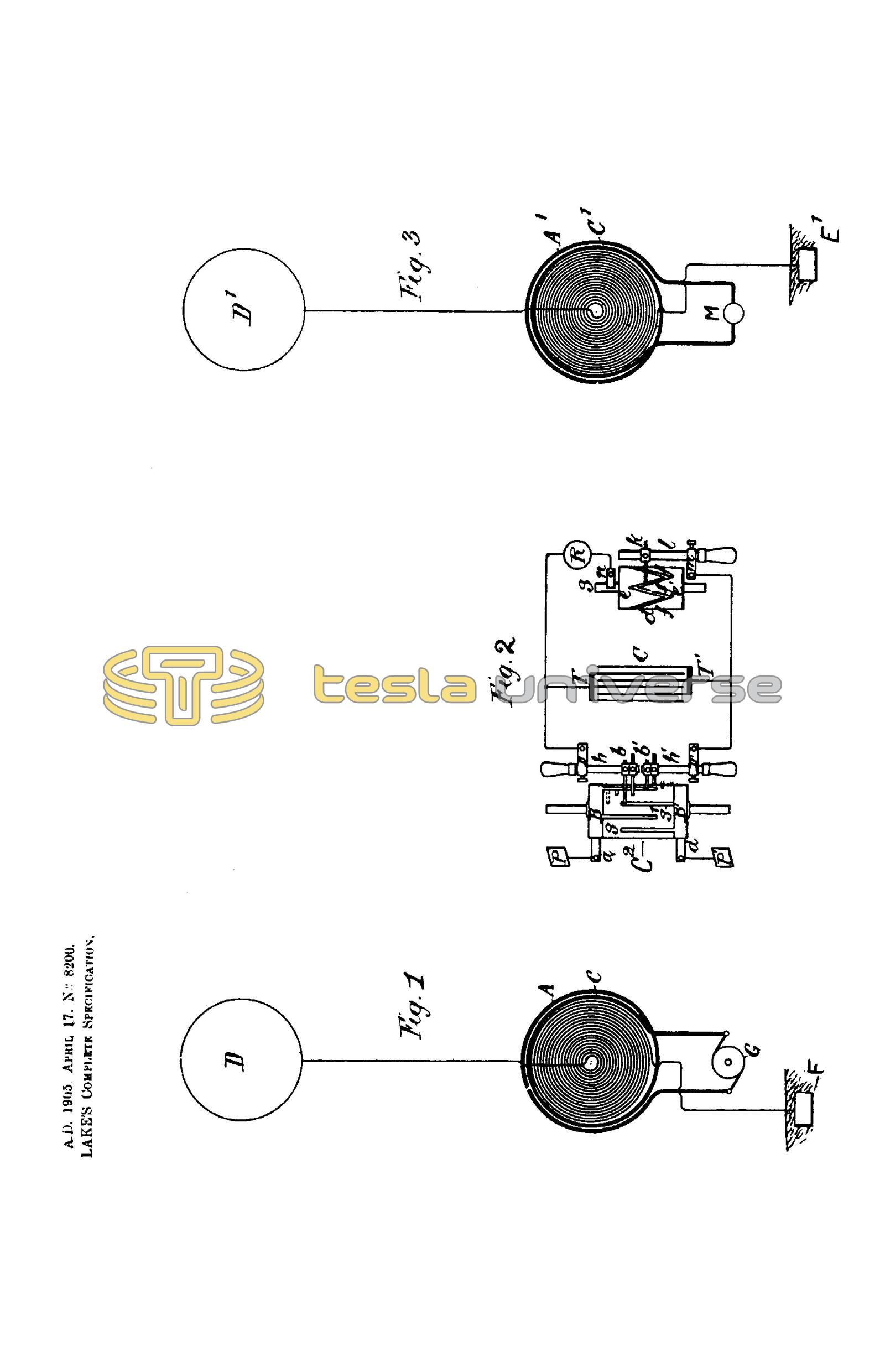
I shall typically illustrate the manner of applying my discovery by describing one of the specific uses of the same, namely, the transmission of intelligible signals or messages between distant points, and with this object reference is now made to the accompanying drawing, in which; -
Figure 1 represents diagrammatically the generator which produces stationary waves in the earth,
Figure 2 an apparatus, situated in a remote locality, for recording the effects of these waves, and
Figure 3 the usual arrangement of the circuits of my receiving transformer.
In Figure 1 A designates a primary coil forming part of a transformer and consisting generally of a few turns of a stout cable of inappreciable resistance, the ends of which are connected to the terminals of a source of powerful electrical oscillations, diagrammatically represented by G. This source is usually a condenser charged to a high potential, and discharged, in rapid succession through the primary, as in a type of transformer invented by me and now well known, having been described in my patents on apparatus of this kind, of which it will be sufficient to mention my British Patent No. 20,981 of 1896. But when it is desired to produce stationary waves of great lengths, an alternating dynamo of suitable construction may be used to energize the primary A.
C is a spirally wound secondary coil within the primary, having the end nearer the latter connected to the ground E, and the other to an elevated terminal D. The physical constants of coil C, determining its period of vibration, are so chosen and adjusted, that the secondary system E C D is in the closest possible resonance with the oscillations impressed upon it by the primary A. It is moreover, of the greatest importance, in order to still further enhance the rise of pressure and to increase the electrical movement in the secondary system, that its resistance be as small as practicable and its self-induction as large as possible under the conditions imposed. The ground should be made with great care, with the object of reducing its resistance.
Instead of being directly grounded, as indicated, the coil C may be joined, in series or otherwise, to the primary A, in which case the latter will be connected to the plate E. But be it that none, or a part, or all of the primary or exciting turns are included in the coil C, the total length of the conductor from the ground plate E to the elevated terminal should be equal to one quarter of the wave-length of the electrical disturbance in the system E C D, or else equal to that length multiplied by an odd number. This relation being observed, the terminal D will be made to coincide with the points of maximum pressure in the secondary or excited circuit, and the greatest flow of electricity will take place in the same. In order to magnify the electrical movement in the secondary as much as possible, it is essential that its inductive connection with the primary A should not be very intimate, as in ordinary transformers, but loose, so as to permit free oscillation. That is to say, their mutual induction should be small. The spiral form of coil C secures this advantage, while the turns near the primary A are subjected to a strong inductive action and develop a high initial electromotive force.
These adjustments and relations being carefully completed, and other constructive features indicated rigorously observed, the electrical movement produced in the secondary system by the inductive action of the primary A will be enormously magnified, the increase being directly proportionate to the inductance and frequency, and inversely to the resistance of the secondary system. I have found it practicable to produce in this manner an electrical movement thousands of times greater than the initial, that is, the one impressed upon the secondary by the primary A, and I have thus reached activities or rates of flow of electrical energy in the system E C D, measured, by many tens of thousands of horse-power. Such immense movements of electricity give rise to a variety of novel and striking phenomena, among which are those already described. The powerful electrical oscillations in the system E C D, being communicated to the ground, cause corresponding vibrations to be propagated to distant parts of the globe, whence they are reflected and, by interference with the outgoing vibrations, produce stationary waves, the crests and hollows of which lie in parallel circles, relatively to which the ground plate E may be considered to be the pole. Stated otherwise, the terrestrial conductor is thrown into resonance with the oscillations impressed upon it just like a wire. More than this, a number of facts ascertained by me clearly show, that the movement of electricity through it follows certain laws with nearly mathematical rigor. For the present it will be sufficient to state, that the earth behaves like a perfectly smooth or polished conductor of inappreciable resistance, with capacity and self-induction uniformly distributed along the axis of symmetry of wave propagation and transmitting slow electrical oscillations without sensible distortion and attenuation. Besides the above, three requirements seem to be essential to the establishment of the resonating condition.
- The earth's diameter passing through the pole should be an odd multiple of the quarter wave-length, that is, of the ratio between the velocity of light and four times the frequency of the currents.
- It is necessary to employ oscillations, in which the rate of radiation of energy into space in the form of Hertzian or electromagnetic waves is very small. To give an idea I would say, that the frequency should be smaller than twenty thousand per second, though shorter waves might be practicable. The lowest frequency would appear to be six per second, in which case there will be but one node, at or near the ground plate, and, paradoxical as it may seem, the effect will increase with the distance and will be greatest in a region diametrically opposite the transmitter. With oscillations still slower the earth, strictly speaking, will not resonate, but simply act as a capacity, and the variation of potential will be more or less uniform over its entire surface.
- The most essential requirement is, however, that irrespective of frequency, the wave or wave train should continue for a certain interval of time, which I have estimated to be not less than one twelfth - or probably 0.08484 - of a second, and which is taken in passing to, and returning from the region diametrically opposite the pole, over the earth's surface, with a mean velocity of about 471,240 kilometers per second.
The presence of the stationary waves may be detected in many ways. For instance, a circuit may be connected directly, or inductively, to the ground and to an elevated terminal, and tuned to respond more effectively to the oscillations. Another way is to connect a tuned circuit to the ground and to two points lying more or less in a meridian passing through the pole E, or generally stated, to any two points of a different potential.
In Fig. 2 I have shown a device for detecting the presence of the waves, such as I have used in a novel method of magnifying feeble effects, which I have described in my United States Patents Nos. 685,953 and 685,955 and my British Patent No. 11,293 of 1901. It consists of a cylinder C2 of insulating material which is moved at a uniform rate of speed, by clockwork or other suitable motive power, and is provided with two metal rings B B1, upon which bear brushes a and a1, connected respectively, to the terminal plates P and P1. From the rings B and B1 extend narrow metallic segments S and S1, which, by the rotation of the cylinder C2 are brought alternately into contact with double brushes b and b1, carried by, and in contact with, conducting holders h and h1, supported in metallic bearings D and D1, as shown. The latter are connected to the terminals T and T1 of a condenser C, and it should be understood that they are capable of angular displacement, as ordinary brush supports. The object of using two brushes, as b and b1, in each of the holders h and h1, is to vary at will the duration of the electric contact of the plates P and P1, with the terminals T and T1, to which is connected a receiving circuit including a receiver R, and a device performing the duty of closing the receiving circuit at predetermined intervals of time and discharging the stored energy through the receiver. In the present case this device consists of a cylinder d made partly of conducting and partly of insulating material e and e1, respectively, which is rotated at the desired rate of speed by any suitable means. The conducting part e is in good electrical connection with the shaft S, and is provided with tapering segments f f f, upon which slide a brush k supported on a conducting rod l, capable of longitudinal adjustment in a metallic support m. Another brush n is arranged to bear upon the shaft S, and it will be seen that, whenever one of the segments f comes in contact with the brush k, the circuit including the receiver R is completed and the condenser discharged through the same. By an adjustment of the speed of rotation to the cylinder d and a displacement of the brush k along the cylinder the circuit may be made to open and close in as rapid succession, and remain open or closed during such intervals of time, as may be desired.
The plates P and P1, through which the electrical energy is conveyed to the brushes a and a1, may be at a considerable distance from each other in the ground, or one in the ground and the other in the air, preferably at some height. If but one plate is connected to the earth and the other maintained at an elevation, the location of the apparatus must be determined with reference to the position of the stationary waves established by the generator, the effect evidently being greatest in a maximum, and zero in a nodal region. On the other hand, if both plates be connected to earth, the points of connection must be selected with reference to the difference of potential, which it is desired to secure, the strongest effect being, of course, obtained when the plates are at a distance equal to half the wave-length.
In illustration of the operation of the system, let it be assumed that alternating electrical impulses from the generator are caused to produce stationary waves in the earth, as above described, and that the receiving apparatus is properly located with reference to the position of the nodal and ventral regions of the waves. The speed of rotation of the cylinder C2 is varied until it is made to turn in synchronism with the alternate impulses of the generator, and the position of the brushes b and b1 is adjusted by angular displacement, or otherwise, so that they are in contact with the segments S and S1 during the periods when the impulses are at, or near, the maximum of their intensity. These requirements being fulfilled, electrical charges of the same sign will be conveyed to each of the terminals of the condenser, and with each fresh impulse it will be charged to a higher potential. The speed of rotation of the cylinder d being adjustable at will, the energy of any number of separate impulses may thus be accumulated in potential form and discharged through the receiver R upon the brush k coming in contact with, one of the segments f. It will be understood, that the capacity of the condenser should be such as to allow the storing of a much greater amount of energy than is required for the ordinary operation of the receiver. Since by this amount a relatively great amount of energy, and in suitable form, may be made available for the operation of a receiver, the latter need not be very sensitive. But, when the impulses are very weak, or when it is desired to operate a receiver very rapidly, any of the well-known sensitive devices, capable of responding to very feeble influences, may be used in the manner indicated or in other ways.
Under the conditions described it is evident that during the continuance of the stationary waves, the receiver will be acted upon by current impulses more or less intense, according to its location with reference to the maxima and minima of said waves, but upon interrupting or reducing the flow of the current the stationary waves will disappear or diminish in intensity. Hence a great variety of effects may be produced in a receiver according to the mode, in which the waves are controlled. It is practicable, however, to shift the nodal and ventral regions of the waves at will from the sending station, as by varying the length of the waves under observance of the above requirements. In this manner the regions of maximum and minimum effect may be made to coincide with any receiving station or stations. By impressing upon the earth two or more oscillations of different wave-length a resultant "stationary" wave may be made to travel slowly over the globe, and thus a great variety of useful effects may be produced. Evidently, the course of a vessel may be easily determined without the use of a compass, as by a circuit connected to the earth at two points, for the effect exerted upon the circuit will be greatest when the plates P P1 are lying on a meridian passing through ground plate E, and will be nil when the plates are located at a parallel circle. If the nodal and ventral regions are maintained in fixed positions the speed of a vessel carrying a receiving apparatus may be exactly computed from observations of the maxima and minima regions successively traversed. This will be understood when it is stated, that the projections of all the nodes and loops on the earth's diameter passing through the pole, or axis of symmetry of the wave-movement, are all equal. Hence in any region at the surface the wave length can be ascertained from simple rules of geometry. Conversely, knowing the wave-length, the distance from the source can be readily calculated. In like ways the distance of one point from another, the latitude and longitude, the hour, etc., may be determined from the observation of such stationary waves. If several such generators of stationary waves - preferably of different lengths - were installed in judiciously selected localities, the entire globe could be sub-divided in definite zones of electric activity and such and other important data could be at once obtained by simple calculation or readings from suitably graduated instruments.
The specific plan of producing the stationary waves, herein described, might be departed from. For example, the circuit which impresses the powerful oscillations upon the earth might be connected to the latter at two points.
In collecting the energy of these disturbances in any terrestrial region at a distance from their source, for any purpose, and, more especially, in appreciable amounts, the most economical results will be generally secured by the employment of my synchronized receiving transformer. This invention forming part of my system of transmission of energy through the natural media, has been fully explained in the patents first cited here, but for the better understanding of the present description it is diagrammatically illustrated in Fig. 3. Its most essential part is a circuit E1 C1 D1 which is connected, arranged and adjusted similarly to the transmitting circuit E C D and which is inductively linked with a secondary circuit A1. The latter, it scarcely need be stated, may be wound with any desired number of turns, such as will be best suited for the operation of the device designated by M. The receiving transformer is closely attuned to the oscillations of the transmitting circuit so that, irrespective of the length of the conductor E1 C1 A1, the points of maximum potential coincide with the elevated terminal D1, under which conditions the greatest amount of wave energy may be collected and rendered available in the secondary circuit A1 for useful purposes.
To complete this description, it may be stated that when it is desired to operate, independently, a great many receiving devices, by such stationary waves of different lengths, the principles which I have set forth in my British Patent 14,579 (1901) and in my United States Patents Nos. 723,188 and 725,605 (1903) may be resorted to for rendering the signals or quantities of energy intended for any particular receiver or receivers non-interfering and non-interferable.
In the above, I have briefly outlined my discovery and indicated only a few uses of the same, but it will be readily seen, that it is of transcending importance for the advancement of many arts and industries, new and old, and capable of innumerable valuable applications.
Having now particularly described and ascertained the nature of this invention and in what manner the same is to be performed, as communicated to me by my foreign correspondent, I declare that what I claim is:-
- The improvement in the art of transmitting electrical energy to a distance which consists in establishing stationary electrical waves in the earth, as set forth.
- A system in accordance with Claim 1 which consists in establishing in the natural conducting media, stationary electrical waves of predetermined length and operating thereby one or more receiving devices remote from the source of energy and properly located with respect to the position of such waves as herein set forth.
- The improvement in the art of transmitting electrical energy, which consists in producing in the earth stationary electrical waves of different lengths, varying their lengths, and causing thereby a resultant wave or effect to travel with the desired velocity over the earth, as above described.
- The method of producing effects at a distance, which consists in impressing upon the terrestrial globe stationary electrical waves, varying their characteristics and relations, and causing thereby corresponding effects in distant receivers, as above described.
- The improvement in the art of transmitting and distributing electrical energy, which consists in producing in the terrestrial globe intersecting trains of stationary electrical waves, establishing thereby regions of definite electrical activities, and collecting the energy, as above set forth.
- The method of producing electrical effects increasing with the distance which consists in impressing upon the earth electrical oscillations of a frequency of about six per second and of such character as to give rise to a stationary electrical wave, as set forth.
- The method of producing great electrical movements in the terrestrial globe, which consists in rendering it resonant by impressing upon it electrical waves of definite length and duration, as above specified.
- In the system as hereinbefore described for the transmission of electrical energy, generating apparatus adapted for producing a resonant condition in the terrestrial globe, as above specified.
- In the system as hereinbefore described for the transmission of electrical energy, a transformer adapted for the production of great electrical movements in the terrestrial globe, as above specified.
- In the system as hereinbefore described for the transmission of electrical energy, a source of primary electrical oscillations such as a condenser circuit and a secondary circuit inductively linked with the same and adapted for throwing the terrestrial globe into resonance, as above specified.
Dated this 17th day of April, 190
Haseltine, Lake & Co.,
7 & 8 Southampton Buildings, London, W.C.
Agents for the Applicant.