Nikola Tesla Patents
Nikola Tesla German Patent 143453 - Method and Device for Secure Transmission by Means of Electrical Impulses
Patent No. 143 453
Class 21.
Nikola Tesla in New York. (V. St. A.).
Method and device for the secure transmission of a message from a specific recipient by means of electrical impulses or vibrations of various types.
Patented in the German Empire on July 23, 1901. Issued August 12, 1903.
We already know methods and devices for generating and transmitting electrical impulses or vibrations through the air, earth or water to receiving devices and for triggering the latter for signaling or the control of other devices, which can be of any type and independent.
In these methods, the receiving devices have been tuned to the transmitters in order to make them even more sensitive to the pulses generated by the latter and to withdraw them as far as possible from the effects of pulses from external sources. However, this arrangement allows only limited secrecy of the pulses to be transmitted because it is very difficult to build any significant number of devices for such methods which respond exclusively to pulses or vibrations of a certain type.
The present invention relates to a method for allowing a large number of transmitting and receiving stations to work simultaneously, separately and exclusively, without exposing the characters or messages to any disturbance, interruption or influence from outside. The method is based on the application of one, two or more electrical pulses or vibrations with different wavelengths generating transmitting device and a receiving device set up a long way away with two or more departments that respond separately to these pulses or vibrations and a receiver (relay or the like.), The only comes into operation when these departments work together at the same time. Any desired working device can then be triggered by the receiver, e.g. a telegraph device, a semaphore arm, a clockwork, an automatically moving ship, etc.
It is true that it is not new to use ether waves of different wavelengths and the same level of vibration; Jégou already pointed this out in the Comptes Rendus (volume 131, page 882). However, the purpose for which the use of such waves has been suggested is quite different.
Generating electrical impulses or vibrations of various types is just as little new. It has also already been proposed (see American patent specification 663400) to have such vibrations picked up at the receiving point by an equal number of receivers, each of which only responds to a specific one of these vibrations, and a specific signaling device only when both receiving devices respond at the same time comes into action. According to the cited patent, vibrations of different directions of vibration, respectively. Level of vibration used. In contrast, the present invention is a method and a device for transmitting messages by means of electrical waves of different wavelengths, and this method is not only characterized by its simplicity, but also by the reliability of its effect.
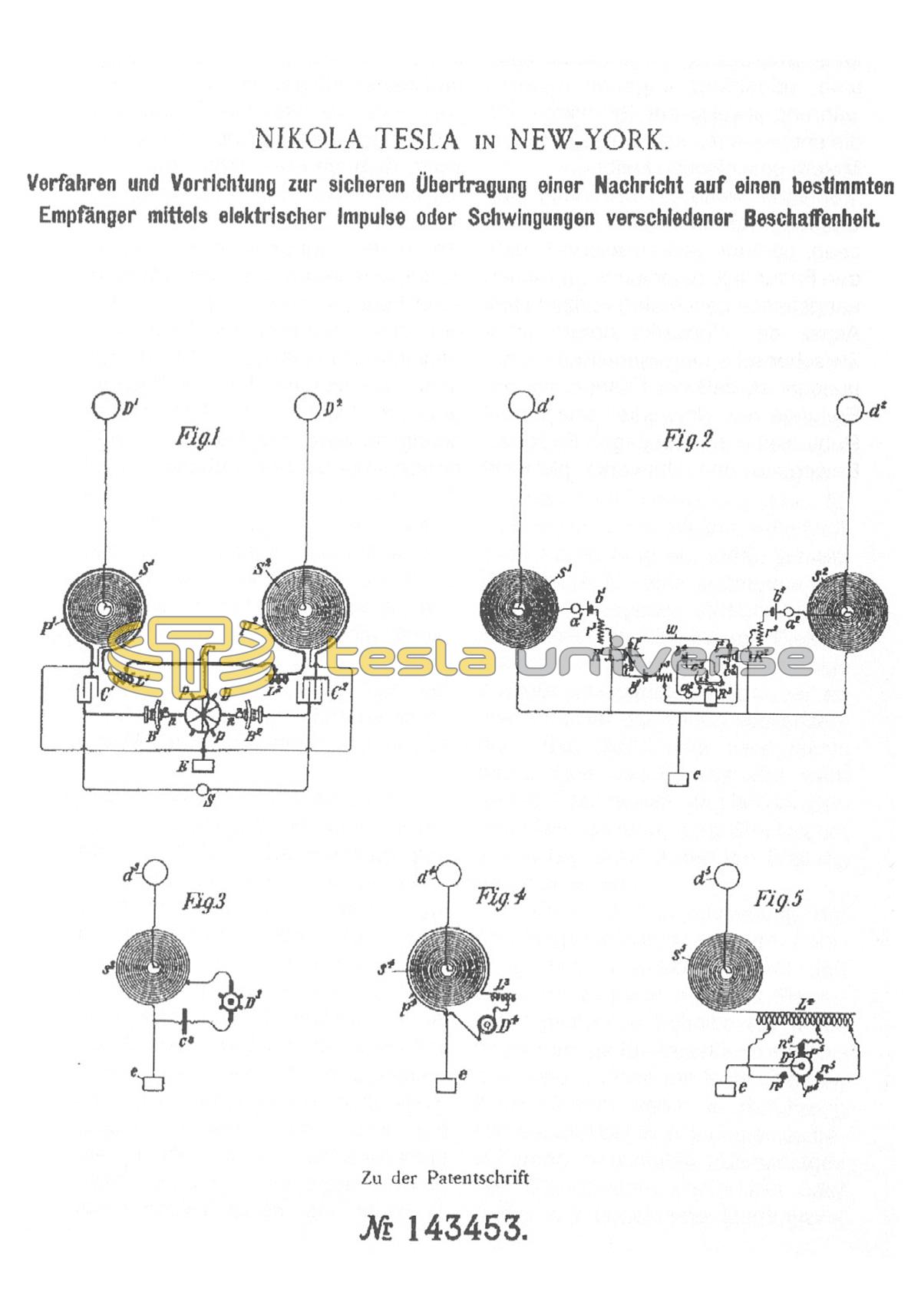
1 and 2 in the accompanying drawing schematically illustrate the devices and circuits used on the transmitting station and the receiving station, respectively. 3, 4 and 5 relate to other embodiments which can be used for the transmitter according to the present invention.
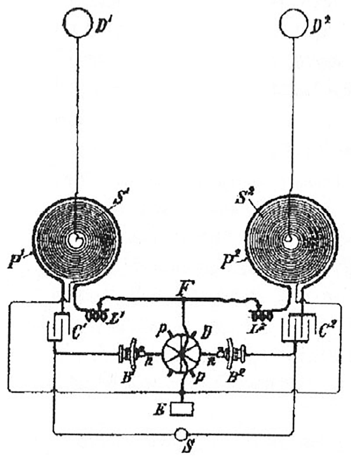
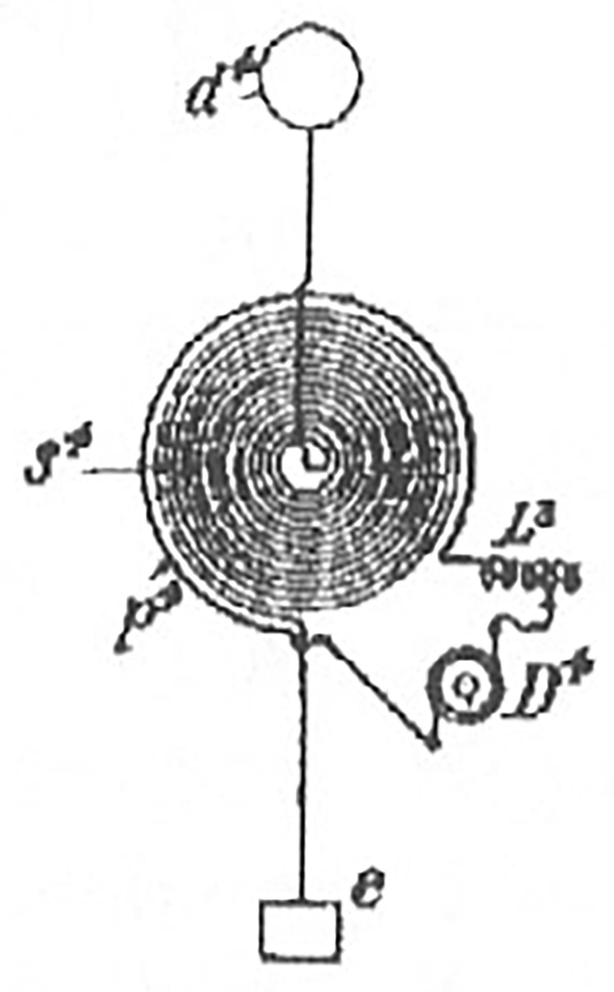
In Fig. 1, two spirally wound coils or conductors S1 S2 are shown, which at their inner ends with an air conductor and high end plates D1 or D2, and are connected to an earth plate E at their outer ends. The two coils or conductors respectively. Vibration systems D1 S1 E and D2 S2 E are excited with different, suitably selected vibration periods and their wire length must be dimensioned in such a way that tension bulges occur in the end plates D1 D2. The oscillation periods must also be chosen in such a way that the oscillations which excite one oscillation system have no effect on the other oscillation system and vice versa. The best results are obtained when the number of vibrations is related to one another like two small prime numbers. In addition, the vibration systems D1 S1 E and D2 S2 E must have low damping so that they do not fade away so quickly, but rather emit wave sequences that continue for as long as possible. Furthermore, the wavelengths used should not be chosen too small, so that they approximate the wavelengths of Hertz's waves, because waves of such a small wavelength turn out to be too weak due to the rapid radiation of the energy into the room. The two vibration systems D1 S1 E and D2 S2 E should rather vibrate in their fundamental tone or at least in a low overtone, because then the possibility of influencing from external disturbing vibrations is lowest. Electrical vibrations can be imparted to the two vibration systems in any way, preferably in such a way that they are excited by primary conductors P1 and P2 arranged in their vicinity. Adjustable inductive resistors L1 L2 are expediently switched into the primary oscillation systems, mainly to regulate the type of primary oscillations. In the drawing, the primary conductors P1 and P2 surround the pulses S1 and S2 and are connected to one another in series through the resistors L1 and L2, conductors F, capacitors C1 and C2, brush holders B1 and B2 and the toothed disc D. The toothed disc D is connected to the conductor F, if desired also to the earth plate E, as illustrated. In this way, two independent primary oscillation systems are formed. The capacitors C1 and C2 have such a capacitance, and the resistors L1 and L2 are switched on in such a way that each primary oscillation system is almost in resonance with its secondary system. Care must be taken that each secondary oscillation system D1 S1 E and D2 S2 E oscillates in its fundamental tone, otherwise the device will not work satisfactorily. If the capacities of the coils S1 and S2 are relatively small, the correct coordination results when the product of the capacitance and self-induction for each primary oscillation system is approximately four times the corresponding product for the associated secondary oscillation system. The brush holders B1 and B2 can be adjusted independently of one another at an angle and, if necessary, laterally, so that any sequence or any phase difference between the discharges occurring in the two primary oscillation systems can be achieved. The capacitors C1 and C2 are charged by any energy source S, expediently from a high potential. If the toothed disk D is set in rotation, its teeth or arms p p come one after the other into the closest vicinity of the conductive rods or brushes n n, or they may touch them, and the capacitors are thereby discharged in rapid succession by their associated oscillation systems. As a result, the two secondary oscillation systems D1 S1 E and D2 S2 E are set in oscillation, each in its own way for a certain period of time after each discharge. The two pulses or vibrations of different wavelengths are communicated to the earth through the earth plate E and reach the receiving station (Fig. 2). The latter is equipped with two similar oscillation systems e s1 d1 and e s2 d2 arranged in the same way as the oscillation systems of the transmitting station and coordinated with the same, so that each of them is exclusively based on one of the two vibrations of different length generated in the transmitting station appeals to. The same principles apply to the receiving station as to the sending station. It must be ensured that the coordination is present when all devices are switched off and are in the correct position, because every change here would more or less influence and change the vibrations. At the beginning and the end of the receiving coils s1 and s2, circuits are connected, each with a device a1 and a sensitive to the electrical vibrations. a2, a battery b1, respectively. b2, an adjustable resistor r1 respectively. r2 and a sensitive relay R1 respectively. R2 included in series connection, as Fig. 2 illustrates. The type of connection and the arrangement of the various devices is largely secondary and can be varied in many ways. The devices a1 a2 sensitive to electrical vibrations can be of any known type. For example, they can each consist of two electrodes separated by a very thin layer of air or dielectric, which are brought to such a high potential difference by a battery or other energy source that the breakdown limit is almost reached; at the slightest disturbance, the dielectric will break down. The original sensitive state can be restored after each discharge by opening the battery power for a moment or in another way. The relays R1 R2 have armature l1 l2, which are connected to each other by a wire w and when they are attracted by contact with the contacts c1 and c2 close a circuit that contains a battery b3, an adjustable resistor r3 and a relay R3 serving as a receiver. It can thus be seen that the relay R3 can only come into operation when both contacts c1 and c2 come into contact with their armatures.
The transmission of vibration sequences of different lengths from the transmitting station (corresponding to the dots and dashes of the Morse code) can be effected in any way, for example by opening and closing the circuit of the energy source S, so that each time it closes two electrical vibrations of different wavelengths at the same time or in be sent out in rapid succession at will. The two receiving vibration systems of the receiving station, which respond individually to the vibrations generated by the corresponding vibration systems of the transmitting station, excite the relays R1 and R2 through the sensitive devices a1 and a2, whose armatures close their circuit through the contacts c1 and c2 and so as activate relay R3 serving the receiver. The latter attracts its armature, which by contacting the contact c3 closes the circuit of the battery b4 and thereby activates a working device a3. If, however, an oscillation sequence of a certain wavelength sent out by an unauthorized party only excited oscillations in one of the two circuits, relay R3 could of course not be activated either. In this way, for example, a message transmission can be effected with increased security against foreign interference, and consequently the confidentiality of the message can also be ensured. The receiving station illustrated in Fig. 2 is unable to send a message to the sending station. However, if both stations are to be able to both send and receive messages, they must be set up in the same way. Any arrangement, which need not be shown here in detail, can then be made in order to be able to use the device on each station both as a transmitter and as a receiver.
The end plates D1 D2 of the transmitting device and those d1 d2 of the receiving device are shown in the drawing as being isolated from one another; however, while advantageous, it is not entirely necessary. The two plates can be interconnected, or there can only be a single end plate D1, respectively. d1 can be used on every station.
The triggering of a receiver, such as R3, can also be made dependent on several transmitter vibration systems instead of two transmitter vibration systems, as described above, so that any degree of security and secrecy of the message against external devices can be achieved in this way.
The devices illustrated in Figs. 1 and 2 also make it possible to achieve different effects by adjusting the sequence or the phase difference of the discharges in the primary oscillation systems P1 and P2. For example, the action of the relays R1 R2 can be regulated either by changing the weight of the armature l1 l2 or the strength of the battery b1 b2 or by adjusting the resistors r1 r2 or in some other way, so that when the discharges in the primary oscillation systems P1 and P2 the transmitting station have a certain phase difference, the armature l1 l2 close their circuits at the same time through the contacts c1 c2 and so switch on the relay R3, but their services fail if the sequence or phase difference is changed. With these or similar means, increased security against external vibrations can be achieved.
Instead of closing and opening the circuit of the current source S in the manner indicated above for the purpose of generating the Morse code, it can be expedient to arbitrarily change the wavelength in each transmission oscillation system in any known way, for example by adjusting the inductive resistances in the primary oscillation systems, so that the transmitter works intermittently, but the receiver only responds when the waves are of the correct length. With regard to the devices illustrated in Fig. 2, it should also be noted that certain effects can be achieved by connecting the contacts c1 and c2 in parallel instead of connecting them in series as shown. In this case too, the relay R3 must be set up or adjusted in such a way that it only comes into operation when both contacts are closed.
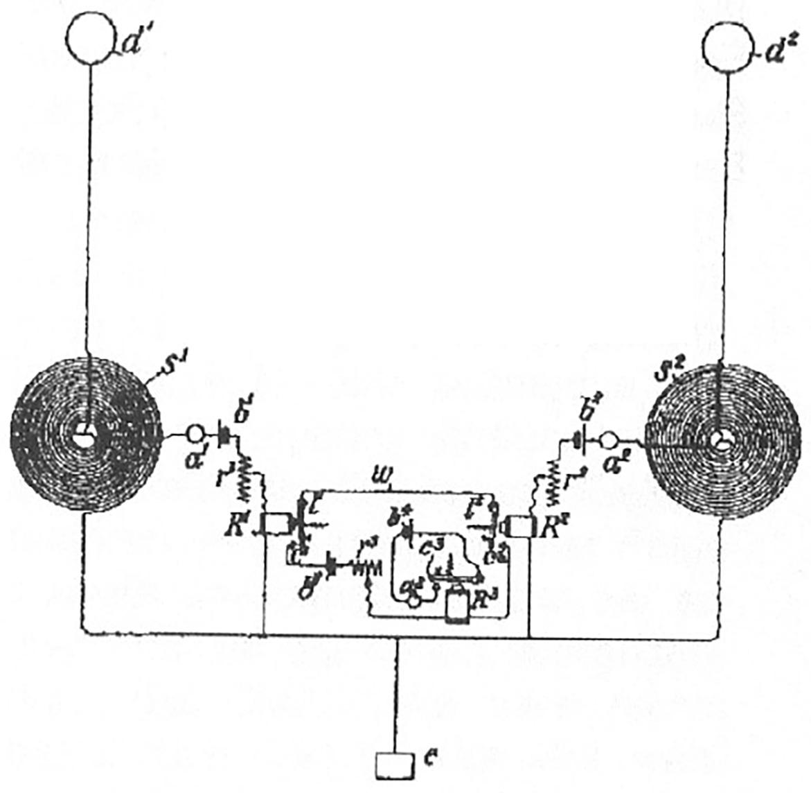
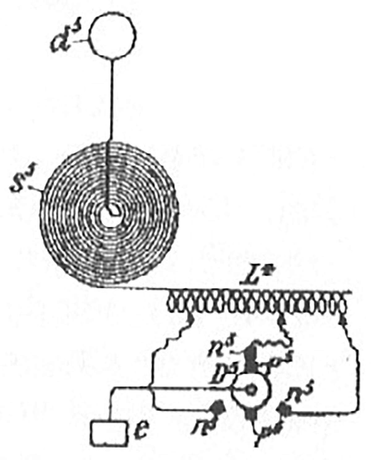
It is not necessary to use transmission devices with two or more separate vibration systems, such as S1 and S2, since a sequence of vibrations of different wavelengths can also be generated by a device with a single vibration system. Some devices of this type are shown in Figs. 3, 4 and 5, for example. 3 shows a transmitting device e s2 d2 in which part of the coil s3 is switched off or short-circuited via an adjustable capacitor C3 in certain periods of time by a rotating disk D3, which can be set up similarly to that shown in Fig. 1 will; As a result, the oscillation of the transmission device e s3 d3 is changed at suitable times, so that two pulses or oscillations of different wavelengths are transmitted in rapid succession. A similar effect is produced in the oscillation system e s4 d4 illustrated in Fig. 4 by temporarily occurring short-circuiting of a secondary winding p4 containing an induction coil L3 by means of a rotating disk D4 with insulating and conductive segments or in some other way. The device e s5 d5 shown in Fig. 5 emits three vibrations of different wavelengths; This is achieved in such a way that a changing number of turns of an induction coil L4 is connected in series with the oscillating system through a rotating disc D5 with two projections p5 p5 and three brushes n5 protruding at 120° from one another. In each of these three cases, the receiving station can use two respectively. Three circuits, similar to that in Fig. 2, whereby the various vibrations emanating from the transmitter must of course follow one another so quickly that they trigger the relays R1 and R2 or the like like simultaneously occurring vibrations. It is also not necessary to use two or more circuits s1 and s2 on the receiving station, but simple circuits such as those shown in Figs. 3, 4 and 5 can also be used. In this case, the corresponding slices, such as D3, D4 and D5, must run synchronously and in the same phase on the sending station and the receiving station.
Of course, as already noted above, a larger number of oscillations of different wavelengths can be used instead of two; this offers the possibility of triggering a single device from a practically unlimited number; Each device is given a special identifier so that it is completely protected against unauthorized use or interference. The same can therefore be called with complete security without having to fear confusion with countless devices.
Claims:
1. A method for the secure transmission of a message to a certain recipient by means of electrical impulses or vibrations of various types, characterized in that a number of types of impulses or vibrations of different wavelengths are generated and transmitted on the transmitting station and that the same number of vibration systems are used at the receiving station that individually only respond to impulses or vibrations of a certain wavelength and only trigger a receiver when they work together.
2. A transmission device for carrying out the method identified under 1, in which a number of pulses or vibrations of different wavelengths are generated by closing and opening a number of differently tuned vibration systems in rapid succession or by rapidly changing the circuitry of one or more vibration systems.