Nikola Tesla Patents
Nikola Tesla German Patent 47012 - Circuit of a Transformer and the Associated Electricity Generator
Patent No. 47 012
Class 21: Electrical Apparatus.
Nikola Tesla in New York (V. ST. A.).
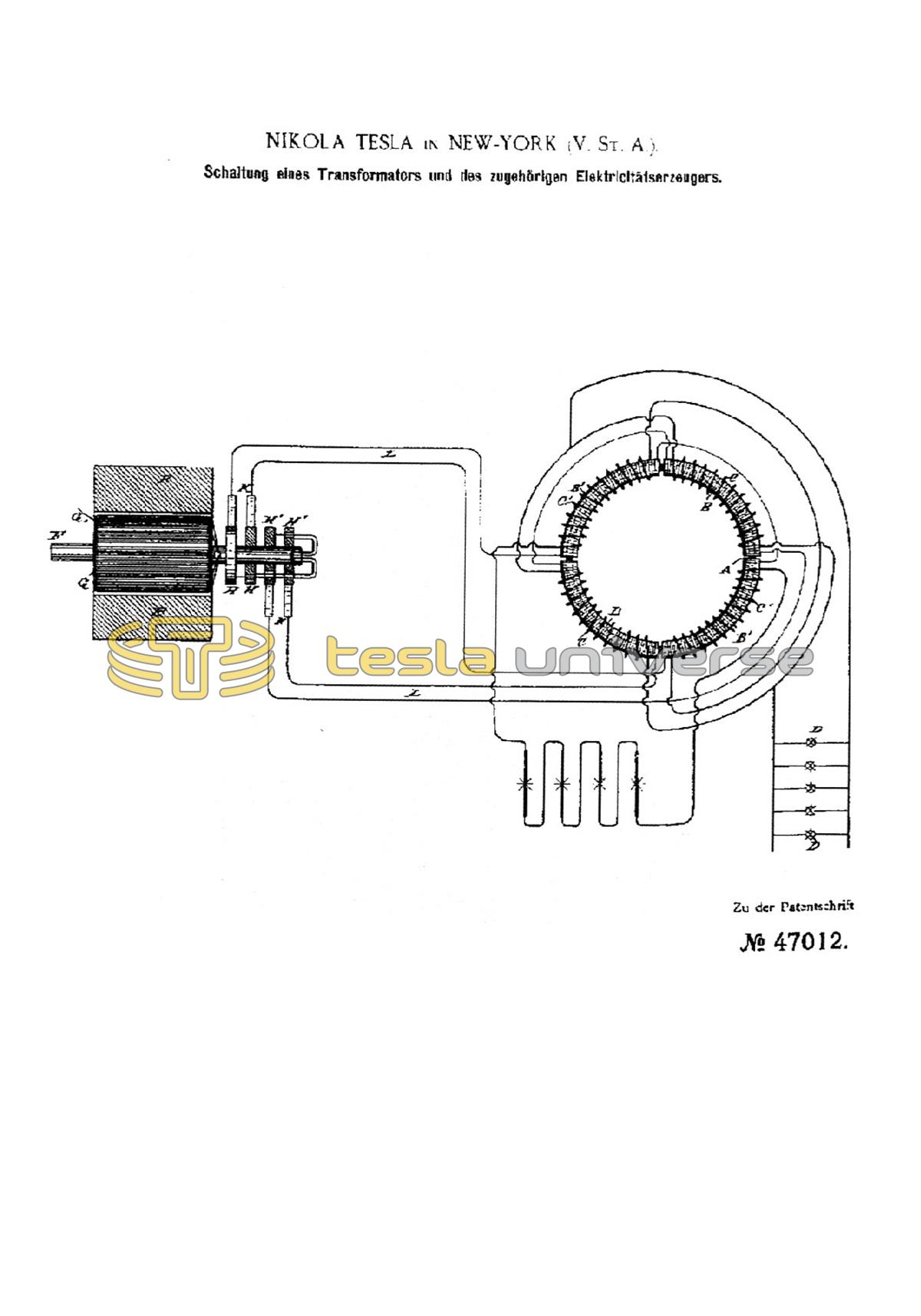
Circuit of a transformer and the associated electricity generator.
Patented in the German Empire on May 1, 1888. Issued May 10, 1889.
The present invention relates to those systems of electrical redistribution in which a current from a single source in a main or transmission circuit is caused by means of appropriate induction rollers to induce one or more currents in one or more special working circuits.
The main purposes of the invention are the same as previously achieved by using the aforementioned systems, that is, to share the current from a single source, thereby independently controlling and operating a number of lamps, motors and other consumption points, from the same power source, and in some cases to reduce a current of high potential in the main circuit to one of greater quantity and lower potential in the consumer circuit or circuits.
The nature of these facilities is well known. A magneto-electric machine for alternating current is used as the power source; the electricity generated in this way is passed through a transmission circuit to one or more points at which the transformers are set up. These in turn consist of induction machines of various types; In some cases, one has used common embodiments of induction rollers, one role of which was arranged in the transmission circuit, the other in a consumption circuit, and the roles were switched differently according to the work to be performed in the consumption circuit, i.e. if the work to be performed was a current of higher potential than that required in the transmission circuit, the secondary or induced role was of greater length and greater resistance than the primary, while conversely, when a current of greater quantity and lower potential was required, the longer role took the place of the primary.
In place of these devices, various embodiments of dynamo-electric induction machines including combined motors and power generators have been proposed.
Without listing the objections to be raised against these systems individually, it should suffice to state that the theory or the operating principle of these devices has evidently been so little recognized that their proper construction and application have been associated with difficulties and great costs until recently.
The risk of being damaged and burned out is very close for transformers and the means previously used to eliminate this risk and other disadvantages have regularly reduced the efficiency.
The method used in the present device consists in moving the line or points of greatest effect in an induction field progressively and continuously over the turns of a coil or conductor which is within the influence of this field and which is part of a secondary or working circuit forms or is included in the latter.
The practice of this invention requires a number of induction rolls and induced rolls, N S, which are wound onto a core such as that used in the Gramme's dynamo machine. The two sets of coils are wound on this core side by side or on top of one another or in any other conventional arrangement to bring them into the most effective relationship with one another and with the core.
The inductive or primary rollers wound on the core are divided into pairs or sets and electrically connected so that while the rollers of one pair or set work together to excite the magnetic poles of the core at two specific diametrically opposed points, the coils of the other pair or set (only two seats in total are assumed here as an example) strive to excite the poles at a distance of 90° from those points.
In connection with this induction device, an alternating current generator is used with coils or sets of coils corresponding to those of the transformer or induction device, and by means of suitable wires the respective coils of the generator and the transformer are connected to form independent circuits. It follows from this that the various electrical changes in the generator are accompanied by corresponding magnetic changes in the transformer, i.e. in other words: that with the rotation of the generator coils the points of greatest magnetic intensity in the transformer are progressively shifted. This principle of operation can be variously modified and adapted to the operation of electromagnetic motors, and the various conditions under which such adaptation takes place will easily lead to the necessary changes in the present system.
A is the closed core, which can have a ring shape or some other similar design and, in order to increase the effect, is made of thin strips, plates or wires of soft iron, which are insulated from one another as much as possible. This core is wrapped in any known manner, for example with four spools B B B1 B1, which are the primary rolls and consist of long, thin wires, over which shorter spools C C C1 C1 of coarser wire, which form the induced or secondary rolls, are wound . The construction of this or any other equivalent embodiment of a transformer can be further carried out by enclosing these coils in iron and, for example, wrapping one or more layers of insulated iron wire around them.
The device is provided with corresponding pole terminals with which the ends of the coils are connected. The diametrically opposed coils B B and B1 B1 are respectively. connected in series and the four pole ends are held in place by the pole clamps. The induced coils are connected together in some way, for example the coils C C can be connected in parallel if, for example, when operating a group of incandescent lamps, the amount of current must be taken into account, while C1 C1 can be connected in series in a circuit including arc lamps or the like.
In this system, the power generator is adapted to the transformer in the manner shown. In the present case, it consists, for example, of a pair of permanent or electromagnets E E, between which a cylindrical armature core, wound with the coils G G1, sits on a shaft F. The pole ends of these coils are respectively. connected to four insulated or collecting rings H H H1 H1, and the four wires L of the line circuit connect the slide springs K, which bear against these rings, to the transformer.
If one looks at the results of this connection, one finds that at a certain point in time the coil G is in its neutral position and generates little or no current, while the other coil G1 is in a position in which it expresses its maximum effect . Assuming now that coil G is electrically connected to coils B B of the transformer and coil G1 to coils B1 B1, the poles of ring A will only be excited in the position shown by the current in coils B1 B1. But since the armature of the power generator continues to rotate, the coil G soon generates more and the coil G1 less current, until G has finally reached its maximum power and G1 has reached its neutral position.
The apparent consequence is a displacement of the poles of the ring A by a distance corresponding to the quarter of the circumference. The movement of the generator coils during the next quarter turn brings coil G1 into a field of opposite polarity and generates a current of opposite direction and increasing strength, while coil G goes from its maximum power position to its neutral position and a current of diminishing strength In in the same direction as before and causes a further shift of the poles over the second quarter of the ring away. The second half of the revolution will, as can be seen, cause the same mode of action to be repeated.
By shifting the poles of the ring A, a strong dynamic and inducing effect is exerted on the coils C C1.
In addition to the currents produced by dynamomagnetic induction in the secondary roll, other currents are produced in the same coils as a result of any change in the intensity of the poles in ring A. This should be avoided by keeping the intensity of the poles constant, whatever the purpose must exercise care when designing and dimensioning the generator, distributing the coils of wire on ring A, and weighing their performance. If this is done, the currents are generated solely by dynamomagnetic induction and the same success is achieved as if the poles were shifted by a commutator with a large number of segments.
Claim:
In transformers, the division of the primary coils into groups that are independent of one another and that are connected to the corresponding armature coils of an electricity generator, which are also divided into groups that are independent of one another, and which are alternately switched into the circuit, generating an induction current by shifting the poles.