Nikola Tesla Patents
Nikola Tesla German Patent 47885 - Connection of the Wire Spools in Electricity Generators with Those of Motors
Patent No. 47,885
Class 21: Electrical apparatus.
Nikola Tesla in New York (V. ST. A.).
Connection of the wire spools in electricity generators with those of motors.
Patented in the German Empire on May 1, 1888. Issued July 17, 1889.
The practical solution to the problem of electrical conversion and transmission of mechanical force contains certain requirements which the apparatus and systems used up to now have not been able to meet.
Such a solution primarily requires a constant speed of the motor under all circumstances, but then it also appears a need to achieve greater savings than before in the conversion, to produce a cheaper, more reliable and simpler apparatus, so that by the same avoid all the dangers and disadvantages that arise from the use of currents of high voltage, such as those required for beneficial transmission.
The present invention comprises a new method and apparatus for effecting transmission of power through electrical switching.
In the practice of the present invention, use is made of a motor having two or more independent excitation circuits through which alternating currents are sent, as described below, causing a progressive shift in magnetism or lines of force which, in accordance with well-known theories, causes the motor to operate.
It will be seen that an appropriate progressive displacement or movement of the lines of force can be harnessed to induce movement or rotation of any element of the motor, the armature of the magnetic field and that when currents conducted through the various circuits of the motor are in the appropriate direction , no commutator is required for the motor. So in order to avoid all the common commutator devices in the system, the motor circuits are directly connected to those of a suitable source for generating alternating currents.
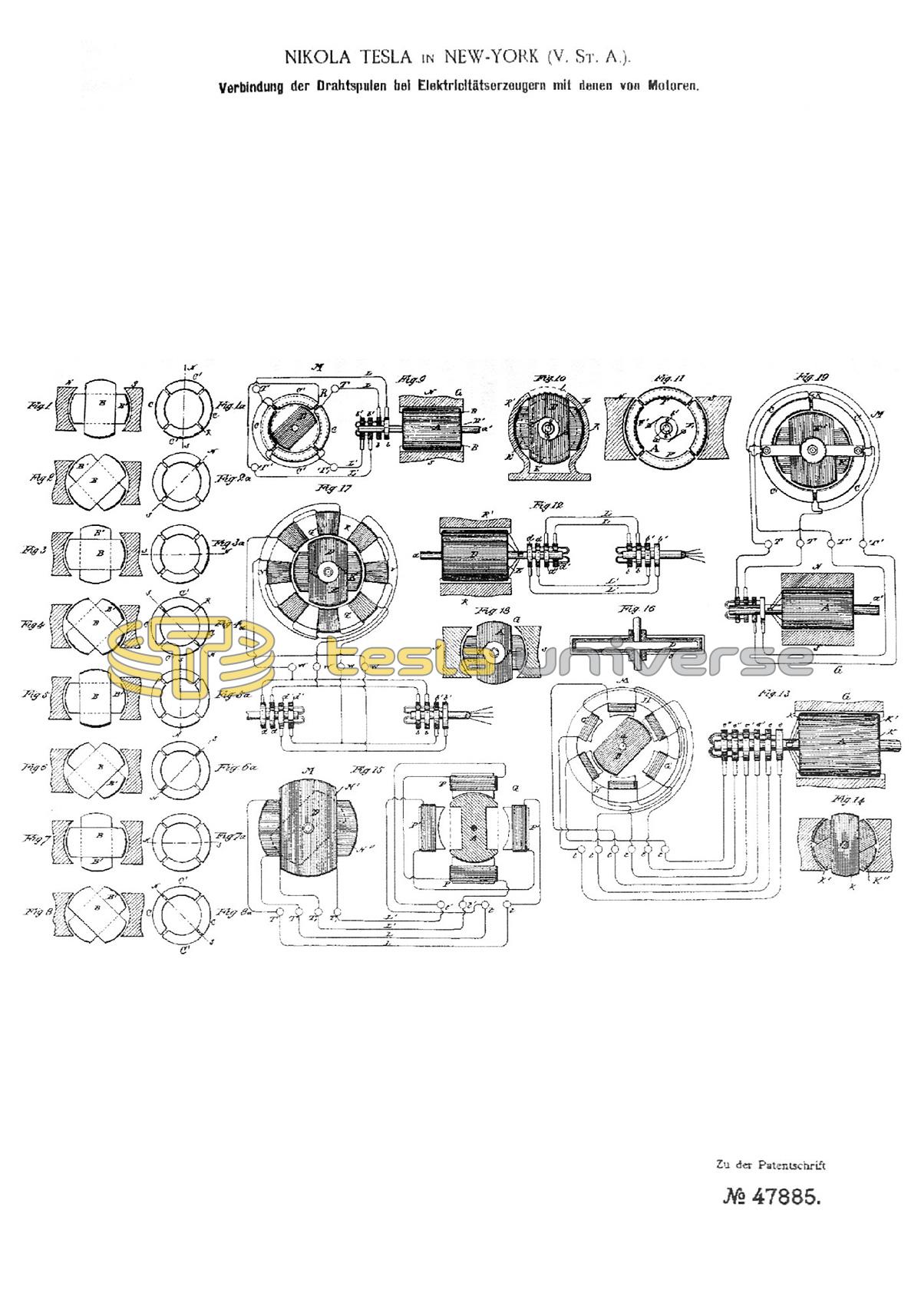
Fig. 1 to 8 and 1a to 8a are designs which illustrate the basic idea of the mode of operation of the present invention. The remaining figures are views of the apparatus in various embodiments, by means of which the invention can be put into practice, and which in their order will be described.
Fig. 9 is a schematic diagram showing a motor, a generator and the connecting circuits in accordance with the invention.
M is the motor and G is the generator driving it. The motor comprises a ring R, best composed of thin insulated iron rings or ring plates so that it is as sensitive as possible to changes in its magnetic state; the same is surrounded by four coils C C C1 C1, which consist of insulated wire and are arranged symmetrically. The diametrically opposed coils are connected so that they cooperate in pairs to produce free poles on diametrically opposed parts of the ring. The remaining four free ends are connected to the clamping screws T T T1 T1, as indicated.
Close to the ring, and preferably inside it, is keyed to a shaft on a shaft which is usually circular in shape, magnetic disk D, which has two recessed segments, as shown, and which rotates freely in ring R.
The generator G is of the usual type and in the drawing has magnetic fields N S and a cylindrical armature core A around which the two coils B B1 are wound; the free ends of each of these coils are passed through the shaft a1 and BEZW. connected to insulated contact rings b b b1 b1.
A slide spring is placed against each ring and forms a pole terminal through which the current is conducted to and from the ring; these pole terminals are connected to the pole terminals TT T1 T1 of the motor by the wires L L1 as shown, whereby two complete circuits are formed, one of which, for example, the coils B of the generator and C1 C1 of the motor, the other the remaining ones Includes coils B1 and CC of the generator and the motor.
It is now superfluous to explain the mode of operation of this system, at what end of the drafts of FIGS. 1 to 8 and 1a to 8a for the purpose of illustrating the various changes which the coils of the generator have to undergo during operation and the corresponding changes that follow magnetic changes generated in the motor.
As can be seen, the rotation of the armature of the generator between the field magnets N S causes alternating currents in the coils B B1, the intensity and direction of which are dependent on the known laws. In the position of the coils indicated in FIG. 1, the current in coil B is practically zero, while coil B1 develops its strongest current at the same time; by means of the devices shown in FIG. 9, the circuit including this coil can also include, for example, the coils C C of the motor, FIG. 1a. The consequence of this would be that, with the aid of the appropriate connections, a magnetization of the ring R would take place, the poles being on the line N-S.
If the same order of connections between coil B and coils C1 C1 is observed, the latter, when a current flows through them, tends to excite the poles at right angles to the line N-S of FIG. 1a. It follows, therefore, that when the generator coils have made an eighth of a turn, currents flow through both pairs of coils C and C1, which counteract each other insofar as the position of the poles is taken into account. The position of the poles is therefore determined by the effect achieved by the magnetizing forces of the coils, i.e. it will advance along the ring to a position which corresponds to an eighth of a turn of the generator armature.
In Fig. 3, the generator armature has advanced a quarter turn. At the point indicated, the current is strongest in coil B, while it is zero in B1 because the latter coil is in its neutral position. The poles of the ring R are consequently shifted in Fig. 3a into a position which deviates by 90 ° from that shown at the beginning. The conditions that exist for each successive eighth of a revolution are illustrated in the same way in the other figures. Brief reference to these figures will suffice to understand their meaning. 4 and 4a illustrate the position after the generator anchor has made a three-eighth turn. Here both coils generate the current, but the coil B1, which has now entered the opposite magnetic field, generates a current in the opposite direction, which has the opposite magnetizing effect. The sending poles will therefore be on the N-S line.
In Fig. 5 and 5a half a revolution is completed with a corresponding movement of the pole line of the motor. At this point, the coil B is in its neutral position, while the coil B1 develops its highest current output, the current having the same direction as in Fig 4.
In Fig. 6 the armature has completed a five-eighth turn. In this position the coil B1 develops a less powerful current, but it has the same direction as last. On the other hand, coil B having entered a field of opposite polarity develops a current of opposite direction. The resulting poles will therefore lie on the line N-S of Fig. 6a, i.e. in other words: the poles of the ring have been shifted along the latter by five eighths of its circumference.
7 and 7a illustrate in the same way the changes of the ring and generator after three quarters of a turn and Fig. 8 and 8a that after seven eighths of a turn of the generator anchor. These figures are easy to understand after the foregoing.
After completion of a complete revolution, the state that was present at the beginning occurs again and the same mode of action is repeated during the next and each subsequent revolution; it follows that each revolution of the generator armature causes a corresponding shift in the poles or lines of force around the ring.
This effect is used to bring about the rotation of a body or an anchor in various ways. If, for example, the principle described above is applied to the apparatus shown in Fig. 9 points of greatest attraction follow.
The disk D shown in Fig. 9 is cut away on its opposite sides, but this is not essential for its mode of operation, since, as also indicated by dotted lines, a circular disk would also be obtained in rotation. This phenomenon is likely to be ascribed to a certain persistence or resistance, which is applied in the metal to the rapid displacement of the lines of force through the same, which results in a constant tangential pull on the disk which causes it to rotate. This seems to be confirmed by the fact that a round steel disk is rotated more efficiently than a soft iron disk because the former is believed to have greater resistance to the displacement of the magnetic lines.
In order to explain other embodiments of the apparatus which enable the practice of the present invention, reference is now made to the remaining figures of the drawings.
Fig. 10 shows an engine partly in elevation and partly in section. Fig. 12 shows the same in the head view with the magnetic field in section and a layout of the connections. Fig. 11 is an end or side view of the generator, also with the magnetic field in section. This embodiment of the motor can be used in place of that described.
D is a cylindrical or drum-shaped armature core which, for obvious reasons, should be cut open as far as possible in order to prevent the circulation of induction currents within it. The core is wrapped lengthways with two coils E E1, whose ends respectively are connected to insulated contact rings d d d1 d1, which sit on the shaft a carrying the armature.
The armature is rotatably arranged in an iron housing R, which forms the magnetic field or another element of the motor. This housing is best provided with a slot or an opening I, but can also, as indicated by dotted lines, be contiguous, and in this case is preferably made of steel. It also appears desirable that this housing be cut open in a manner similar to the armature and for the same reasons.
The generator for operating this engine may be that shown in Fig. 11. It consists of a ring armature A, surrounded by the four coils F F F1 F1, of which the diametrically opposite ones are connected in series, so that four free ends N remain, which are connected to the insulated contact rings b b b1 b1. This ring is arranged on a shaft a1 between the poles N S.
The contact rings of each pair of generator coils are connected to those of the motor or by means of slide springs and the two pairs of conductors L L L1 L1, as shown in the design in Fig. 12.
A comparison of the previous figures shows that the rotation of the generator ring in the coils F F1 generates currents which, after being transferred to the motor coils, give the armature core of the motor magnetic poles which are constantly shifted around the core. This effect causes the motor armature to rotate due to the force of attraction between the housing R and the poles of the armature; but insofar as the coils in this case move in relation to the housing or the magnetic field, the movement of the coils takes place in the opposite direction to the progressive movement of the poles.
Other arrangements of the coils of both the generator and the motor are also possible, and a larger number of circuits can be used, as can be seen from the next two figures.
Fig. 13 shows in outline an engine and generator connected and arranged in accordance with the present invention. Fig. 14 is an end view of the magnetic field generator in section.
The field of the motor M is produced by six magnetic poles G1 G1, which sit on a ring or frame H. These magnets or poles are wound with insulated coils, of which the diametrically opposed pairs are connected to one another so that opposite poles are created in each pair. This results in six free ends which are connected to the pole terminals t.
The armature, which is rotatably arranged between the poles, is a cylinder sitting on the shaft a or a disk D made of wrought iron. Two segments of this disk are cut away as drawn.
In this case, the generator for this motor has an armature A wound with three coils K K' K" at intervals of 60°. The ends of these coils are respectively, with insulated contact rings e e e' e' e" e" connected, which are connected to those of the motor in the appropriate order by means of a collector brush or slide springs and six wires that form independent circuits. The changes in the strength and direction of the current sent through these circuits and running through the motor coils cause a steadily progressive shift in the attractive forces with which the pole G1 act on the armature D and accordingly keep the armature rotating rapidly. The application of this principle to systems which contain side-by-side connected circuits can be easily understood from the foregoing apparatus.
Of Fig. 15 and 16, the former shows an illustration of a modified arrangement of the invention in design, while Fig. 16 shows a cross-section of the engine.
In this case, a disc D made of magnetic metal, which is best cut out on opposite edges, as indicated by dotted lines, is arranged freely rotatable within two stationary coils N' N" which are at right angles to one another. The coils are best wound on a frame O made of insulating material and their ends connected to the binding posts T T T1 T1.
The generator G belongs to the class of machines for alternating current. The one drawn here consists of a rotating permanent or electromagnet A and four independent stationary magnets P P1 wrapped with coils, the diametrically opposite coils being connected in series and attached at their ends to the pole terminals t t t1 t1. The currents are routed from these pole terminals to the pole terminals T T T1 T1 of the motor, as illustrated in the drawing.
The operation is essentially the same as in the previous cases, in that currents passing through the coils of the motor have the effect of rotating the disk D. This way of practicing the invention offers the advantage that the sliding contacts in the system can be dispensed with.
In the above-described embodiments of the motor, only one of the elements, the armature or the field magnet, is provided with exciting coils. It is therefore still superfluous to show how both elements can be wound with coils, to which end reference is made to Fig. 17 and 18. Fig. 17 is an end sectional view of a magnetic field. In Fig. 17 the field magnet of the motor consists of a ring R, which is best formed from thin insulated iron sheets with eight pole pieces G1 and corresponding recesses with four pairs of coils V wound into them. The diametrically opposite coil pairs are connected in series and the free ends are attached to four pole terminals W; with regard to the establishment of the connections, the same rules apply here as above.
An armature D provided with two coils E E1 at right angles to one another is rotatably arranged within the field magnet R: the ends of the armature coils are connected to two pairs of contact rings d d d1 d1.
The generator for this motor can be of any suitable type to generate currents of the desired type. In the present case it consists of a magnetic field N S and an armature A with two coils lying at right angles to one another, the ends of which are connected to four contact rings b b b1 b1 carried by their shaft.
The circuit connections are made between the rings on the generator shaft and those on the motor shaft by slip springs and wires as described earlier. In order to properly excite the field magnet of the motor, however, the connections with the armature coils are made by wires leading to them in such a way that during the displacement of the points of greatest attraction or greatest tightness of the magnetic lines of force on the armature in one direction, those on the electromagnet are made to advance in the opposite direction. In the rest, the mode of action is the same as that described in the previous cases.
This arrangement results in an increased speed of rotation.
For example, in Fig. 17, the pole ends of each set of field coils are connected to the wires of the armature coils in such a way that the field coils maintain opposite poles from the poles of the armature.
In the drawings, the field coils are shunted to the armature, but they can also be connected in series or in independent circuits.
Fig. 19 is a layout similar to Fig. 9 and illustrates a modification of the engine. In this figure the various parts are the same as in Fig. 9, except that the armature core of the motor, which is a cylinder or a disk, is wound with two coils at right angles to each other. The two coils form independent closed circuits.
When a motor constructed in this way is running freely, the rotation of the armature takes place simultaneously with the rotation of the poles in the field, and under these circumstances very little current is noticeable in the coils C1 C, but at a reduced speed the currents in the coil become so amplified that the turning effect is increased in the same proportion.
This principle of construction allows for many modified arrangements, most of which result automatically from the constructions described; for example, the armature or the induced coils, or those in which the currents arise by induction, can be fixed and the alternating currents from the generator can be conducted through the rotating inducing or field coils by means of suitable sliding contacts. It will also be seen that the induced rollers can be movable and the magnetic parts of the motor can be fixed.
A characteristic feature of motors constructed and operated in accordance with this principle is the inherent capacity of almost instantaneous reversal as a result of the turning of one of the exciting currents from the generator.
This becomes understandable from a consideration of the working conditions. Assuming that the armature rotates in a certain direction following the movement of the different poles and that the direction of displacement is then reversed, which can happen by reversing the connection of one of the two exciting circuits, if one takes into account that the in The force developed by a dynamo-electric machine is almost exactly proportional to the cube of the speed, it is evident that at such a moment an extraordinary force is used to reverse the direction of the motor.
Instead of the field magnets illustrated in the drawing, soft iron field magnets excited by a continuous current can be used for the motors.
This proposal offers great advantages, but it is characteristic that if in a motor so operated the field magnet is strongly excited by its coil and the circuits are closed by the armature coils (assuming a certain speed for the generator), the motor will not is concerned, however, that if the magnetic field is only slightly excited or generally in such a state that the magnetic influence of the armature has the over-weight, the motor begins to move and, with sufficient current, reaches its normal or maximum speed. For this reason, it is desirable to keep the circuit of the magnetic field open, or to allow little current to pass through it, while the engine is starting up and until near or all of its normal speed is reached.
Another peculiarity of this motor is that its direction of rotation is not reversed by reversing the direction of the current passing through the field coils, since the direction of rotation does not depend on the polarity of the field but on the direction in which the poles of the armature are shifted. To reverse the motor, the connections of each of the energizing circuits must be reversed.
When the fields of both the generator and the motor are strongly excited, starting the generator causes movement of the motor and increases the movement of the latter at the same time as the generator.
Motors constructed and operated according to this principle maintain the same speed in all cases within their normal working limits, and if the speed of the motor should be inhibited by a sudden overload, the speed of the generator is also reduced at the same time, if its motor power is not is too big. These properties appear to be very useful under certain circumstances in this particular embodiment of the motor.
Having thus described the invention and one of its various forms of application, attention is directed to certain characteristics which the invention presents in its application.
Consideration of the motor shown in Fig. 9 shows that since the disc D tends to constantly follow the points of greatest attraction and the latter are shifted once around the ring for each revolution of the generator armature, the movements of the Disc take place at the same time as those of anchor A. This characteristic can be found in all other embodiments in which one revolution of the generator armature causes the poles of the motor to be shifted by 360°.
In the particular modification shown in Fig. 5 or in other forms of construction based on the same principles, the number of alternating pulses resulting from one revolution of the generator armature is twice that of the previous cases, and the polarities of the motor with one revolution of the generator armature become moved around in a circle twice.
The same effect is achieved by the arrangement of Fig. 17, where the poles of both elements are shifted in opposite directions.
If one looks again at the apparatus of Fig. 9, which is to be regarded as a model for the invention, it follows that, since the attractive effect exerted on the disk D is greatest when the disk is in its corresponding position relative to that on the ring R emerging poles is located; i.e. if their ends or poles immediately follow those of the ring, the speed of the motor is in reality a constant under all circumstances within the normal working limits.
The speed can never exceed the arbitrary limit determined by the generator, and furthermore, at least within certain limits, the motor speed is independent of the current intensity.
It is not new to make a motor rotate by intermittently shifting the poles of one of its elements. This has been done by passing the current from a battery or other source of direct or continuous current through independent excitation coils on one of the elements and then using suitable mechanical means to turn that current so that it passed through the coils in alternating opposite directions . In such cases, however, the potential of the exciting current remains the same and only the direction of the current changes. In accordance with the present invention, on the other hand, purely alternating currents are used, and the invention consists in the manner of operating an apparatus for utilizing such currents.
The difference between the two procedures is: By generating an alternating current, each pulse of which causes the potential to rise and fall, the states of the generator in the motor are precisely reproduced and the poles are advanced continuously and not intermittently.
In addition, the practical difficulty of interrupting or turning a current of any considerable magnitude is so great that none of the devices known heretofore has been able to effect the transmission of force by reversing a continuous or direct current in the manner described.
As far as the method of influencing an element of the motor is concerned, the present invention is based on the use of an alternating current in contrast to a reversed current or a current which is continuous and rectified and from coil to coil with the aid of a commutator, commutator or circuit breaker is moved. With regard to that part of the invention which consists in the simultaneous influencing of both elements of the motor, the use of both alternating and reversed currents is within the scope of the inventive idea, although the use of the latter currents is not given any particular practical importance.
Claim:
A motor whose coils are divided into several separate groups, which are connected to the coils of the electricity generator, which are also divided into separate groups, so that as many independent circuits are formed as there are groups which are connected in such a way that the movement of the motor armature is caused by the displacement of the poles in the motor.