Nikola Tesla Patents
Nikola Tesla U.S. Patent 1,113,716 - Fountain
NIKOLA TESLA, OF NEW YORK, N. Y.
TESLA PATENT 1,113,716 FOUNTAIN.
| 1,113,716. | Specification of Letters Patent. | Patented Oct. 13, 1914. |
Application filed October 28, 1913. Serial No. 797,718.
To all whom it may concern:
Be it known that I, NIKOLA TESLA, a citizen of the United States, residing at New York, borough of Manhattan, county and State of New York, have invented certain new and useful Improvements in Fountains, of which the following is a full, clear, and exact description.
It has been customary heretofore in fountains and aquarian displays, to project spouts, jets, or sprays of water from suitable fixtures, chiefly for decorative and beautifying purposes. Invariably, the quantity of the issuing fluid was small and the pleasing impression on the eye was solely the result of the more or less artistic arrangement of the streamlets and ornaments employed. The present invention is a departure from such practice in that it relies principally on the fascinating spectacle of a large mass of fluid in motion and the display of seemingly great power. Incidentally, it permits the realization of beautiful and striking views through illumination and the disposition of voluminous cascades which, moreover, may be applied to useful purposes in ways not practicable with the old and familiar devices. These objects are accomplished by the displacement of a great volume of fluid with a relatively small expenditure of energy in the production and maintenance of a veritable waterfall as distinguished from a mere spout, jet or spray.
The underlying idea of the invention can be carried out by apparatus of widely varied design, but in the present instance the simplest forms, of which I am aware, are shown as embodiments of the principle involved.
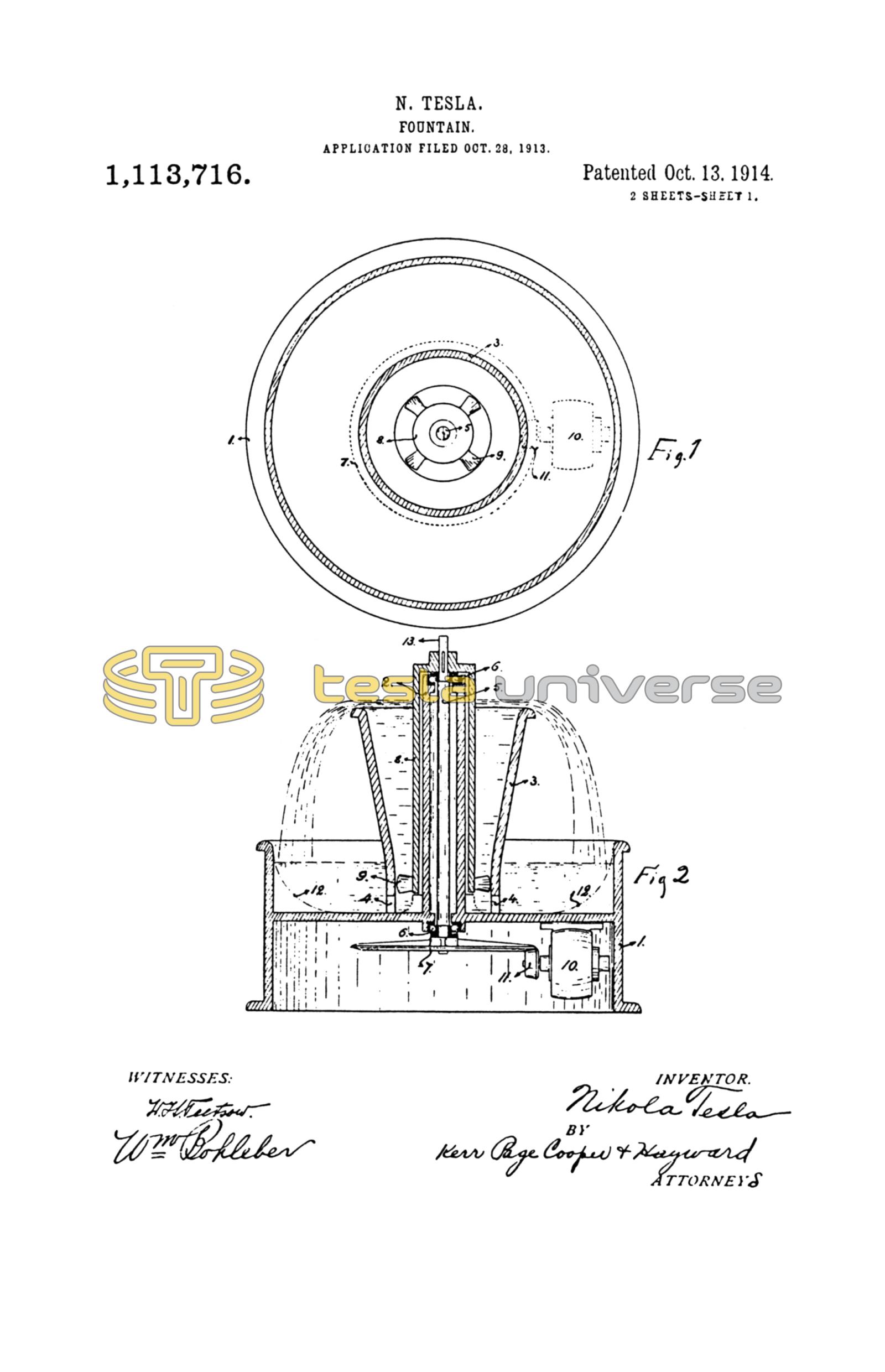
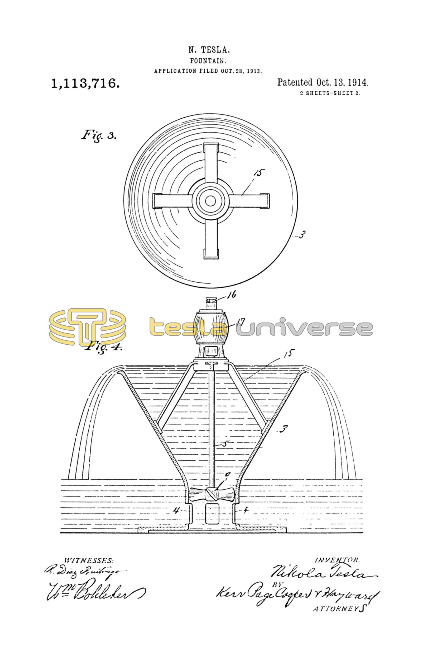
In the accompanying drawing, Figure 1 is a top plan and Fig. 2 a vertical central sectional view of an appliance which I have devised for the purpose. Fig. 3 and Fig. 4 illustrate corresponding views of a similar device of much simpler construction.
Referring to the first, 1 represents a receptacle of any suitable material, as metal, glass, porcelain, marble, cement or other compound, with a central hub 2 and a conical conduit 3, flared out at the top and provided with openings 4 at the bottom. In the hub 2 is inserted a shaft 5 rotatably supported on ball bearings 6 and carrying at its lower end a friction pulley or gear wheel 7. To the upper end of the shaft is fastened a casting 8, preferably of some non-corrosive alloy, with blades 9 constituting a screw which is shown in this instance as the best known propelling device; but it will be understood that other means may be employed. A motor 10 is suitably mounted so as to transmit through wheel 11, by friction or otherwise, power to the pulley or wheel 7. Openings 4 may be covered with removable strainers and receptacles 1 may be provided with convenient connections, respectively, for cleaning and renewing the liquid. It is thought unnecessary to show these attachments in the drawing.
The operation will be readily understood. Receptacle 1 being filled to the proper level with water or other fluid, and the power turned on, the propeller blades 9 are set in rotation and the fluid, drawn through the openings 4, is lifted to the horizontal flared out top of conduit 3 until it overflows in the form of a circular cascade.
In order to prevent the wetting of the bearings of shaft 5, the central hub 2 of receptacle 1 is made to project above conduit 3. The latter is funnel shaped for reasons of economy, and also for the purpose of reducing the speed and securing a smooth and even overflow. As the lift is inconsiderable, little power is needed to keep in motion a great volume of water and the impression produced on the observer is very striking. With the view of still further economizing energy, the bottom of receptacle 1 may be shaped as indicated by the dotted lines 12, in Fig. 2 so as to increase the velocity at the intake of the propeller.
To convey an idea of the results obtainable with a small apparatus, properly designed, it may be stated that by applying only 1/25 of a horse-power to the shaft and assuming a lift of eighteen inches, more than one hundred gallons per minute may be propelled, the depth of the fluid passing over the flared top of conduit 3, one foot in diameter, being nearly one-half inch. As the circulation is extremely rapid the total quantity of liquid required is comparatively small. About one tenth of that delivered per minute will be, generally, sufficient. Such a cascade presents a singularly attractive appearance and this feature may be still further enhanced by artistic grouping of plants or other objects around it, in which case the whole contrivance may be hidden from view. Particularly beautiful displays, however, are obtainable by illumination which may be carried out in many ways. To heighten the effect, a colored, opalescent or phosphorescent fluid may be employed. Sterilizing, aromatic or radio-active liquids may also he used, when so desired. The usual fountains are objectionable in many places on account of the facility they afford for the breeding of insects. The apparatus described not only makes this impossible but is a very efficient trap. Unlike the old devices in which only a very small volume of water is set in motion, such a waterfall is highly effective in cooling the surrounding atmosphere. To still improve this action the free end 13 of the rotating shaft may be utilized to carry any kind of fan. The water may, of course, be artificially cooled.
The device described may be modified in many ways and also considerably simplified. For example, the propeller may be fixed directly to the shaft of the motor and the latter supported conveniently from above when many of the parts illustrated in Fig. 1 and Fig. 2 may be dispensed with. In fact, receptacle 1 itself may be replaced by an independent tank or basin so that the entire apparatus will only consist of a funnel shaped conduit, motor and propeller as a unit. Such a construction is shown in Fig. 3 and Fig. 4 in which 3 is a conical vessel provided with intake openings 4 and resting on a substantial base. A motor 14, carrying on a strong shaft 5 a propeller 9, is fixed to supports 15 which extend from the inner side of conduit 3 and may be integral with the same. Obviously, to insure perfect working the weight of the moving parts and axial reaction of the propeller should be taken up or balanced as by a thrust bearing 16, or other means.
Apparatus of this description is especially intended for use in open basins or reservoirs in which it may be placed and put in action at short notice. When it is desired to produce large and permanent waterfalls the conduit 3 may be formed by masonry of appropriate architectural design.
The invention has an unlimited field of use in private dwellings, hotels, theaters, concert halls, hospitals, aquaria and, particularly, in squares, gardens and parks in which it may be carried out on a larger scale so as to afford a magnificent spectacle far more captivating and stimulating to the public than the insignificant displays now in use.
I am well aware that artificial water falls have heretofore been exhibited and that fountains in which the same water is circulated are old and well known. But in all such cases independent pumps of small volumetric capacity were used to raise the water to an appreciable height which involved the expenditure of considerable energy, while the spectacle offered to the eye was uninteresting. In no instance, to my knowledge, has a great mass of fluid been propelled by the use of only such power as is required to lift it from its normal level through a relatively short space to that from which it overflows and descends as a cascade, nor have devices especially adapted for the purpose been employed.
What I claim is:
1. An artificial fountain consisting of an unobstructed conduit having an elevated overflow and adapted to be set in a body of water, and a propelling device for maintaining a rapid circulation of the water through the conduit.
2. An artificial fountain comprising in combination an unobstructed conduit having an elevated overflow and adapted to be set in a body of fluid, a propeller within the conduit for maintaining a rapid circulation of the fluid through the same, and a motor for driving the propeller.
3. The artificial fountain herein described, comprising in combination a receptacle, a central hollow conduit with an elevated overflow placed herein, a propeller within the conduit, and a motor for driving the propeller, so as to maintain a rapid circulation of fluid through the conduit.
4. The artificial fountain herein described, comprising in combination, a receptacle, a conduit with elevated overflow set therein, a central hub extending up through the conduit, a rotary shaft extending therethrough, and a propeller carried by the shaft for maintaining a rapid circulation of fluid through the conduit.
5. An artificial fountain comprising in combination with an unobstructed passage from the normal to the elevated fluid levels, of a propeller for maintaining a rapid circulation of the fluid through such passage and producing thereby a cascade with the expenditure of little energy.
6. An artificial fountain comprising a funnel shaped conduit adapted to be set in a body of fluid, and having openings near the lower end, and a propeller supported within the conduit and adapted when in operation to maintain a rapid circulation of water through the same.
In testimony whereof I affix my signature in the presence of two subscribing witnesses.
NIKOLA TESLA.
M. LAWSON DYAR,
WM. BOHLEBER.