Nikola Tesla Patents
Nikola Tesla U.S. Patent 350,954 - Regulator for Dynamo-Electric Machines
NIKOLA TESLA, OF SMILJAN LIKA, AUSTRIA-HUNGARY, ASSIGNOR TO THE TESLA ELECTRIC LIGHT AND MANUFACTURING COMPANY, OF RAHWAY, NEW JERSEY.
REGULATOR FOR DYNAMO-ELECTRIC MACHINES.
SPECIFICATION forming part of Letters Patent No. 350,954 dated October 19, 1886.
Application filed January 14, 1886. Serial No. 188,539. (No model.)
To all whom it may concern:
Be it known that I, NIKOLA TESLA, of Smiljan Lika, border country of Austria-Hungary, have invented an Improvement in Dynamo-Electric Machines, of which the following is a specification.
In another applications I have shown the commutator of a dynamo-machine with the main brushes connected in an electric circuit, and one or more auxiliary brushes serving to shunt a part or the whole of the field-coils, the regulation of the current being effected by shifting the respective brushes automatically upon the commutator in proportion to the varying resistances of the circuit.
My present invention relates to the mechanical devices which I employ to effect the shifting of the brushes.
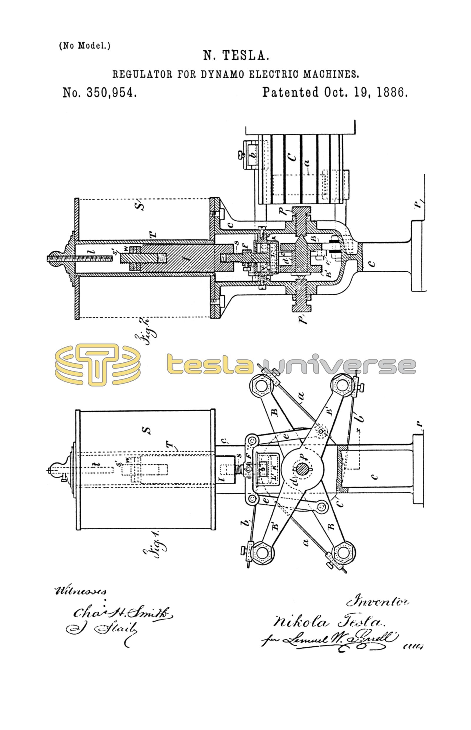
My invention is clearly shown in the accompanying drawings, in which Figure 1 is an elevation of the regulator with the frame partly in section; and Fig. 2 is a section at the line x x, Fig. 1.
C is the commutator; B and B', the brush-holders, B carrying the main brushes a a' and B' the auxiliary or shunt brushes b b. The axis of the brush-holder B is supported by two pivot-screws, p p. The other brush-holder, B', has a sleeve, d, and is movable around the axis of the brush-holder B. In this way both brush-holders can turn very freely, the friction of the parts being reduced to a minimum. Over the brush-holders is mounted the solenoid S, which rests upon a forked column, c. This column also affords a support for the pivots p p, and is fastened upon a solid bracket or projection, P, which extends from the base of the machine, and is preferably cast in one piece with the same. The brush-holders B B' are connected by means of the links e e and the cross-piece F to the iron core I, which slides freely in the tube T of the solenoid. The iron core I has a screw, s, by means of which it can be raised and adjusted in its position relatively to the solenoid, so that the pull exerted upon it by the solenoid is practically uniform through the whole length of motion which is required to effect the regulation. In order to effect the adjustment with a greater precision the core I is provided with a small iron screw, s'. The core being first brought very nearly in the required position relatively to the solenoid by means of the screw s, the small screw s' is then adjusted until the magnetic attraction upon the core is the same when the core is in any position. A convenient stop, t, serves to limit the upward movement of the iron core.
To check somewhat the movement of the core I, a dash-pot, K, is used. The piston L of the dash-pot is provided with a valve, V, which opens by a downward pressure and allows an easy downward movement of the iron core I, but closes and checks the movement of the core when the same is pulled up under the action of the solenoid.
To balance the opposing forces, the weight of the moving parts, and the pull exerted by the solenoid upon the iron core, the weights W W may be used. The adjustment is such that when the solenoid is traversed by the normal current it is just strong enough to balance the downward pull of the parts.
The electrical circuit-connections are substantially the same, as indicated in my former applications, the solenoid being in series with the circuit when the translating devices are in series and in a shunt when the devices are in multiple arc.
The operation of the devices is as follows:
When upon a decrease of the resistance of the circuit or some other reason the current is increased, the solenoid S gains in strength and pulls up the iron core I, thus shifting the main brushes in the direction of rotation and the auxiliary brushes in the opposite way. This diminishes the strength of the current until the opposing forces are balanced and the solenoid is traversed by the normal current; but if from any cause the current in the circuit is diminished, then the weight of the moving parts overcomes the pull of the solenoid, the iron core I descends, thus shifting the brushes the opposite way and increasing the current to the normal strength. The dash-pot connected to the iron core I may be of ordinary construction; but I prefer, especially in machines for arc light, to provide the piston of the dash-pot with a valve, as indicated in the drawings. This valve permits a comparatively easy downward movement of the iron core, but checks its movement when it is drawn up by the solenoid. Such an arrangement has the advantage that a great number of lights may be put on without diminishing the light-power of the lamps in the circuit, as the brushes assume at once the proper position. When lights are cut out, the dash-pot acts to retard the movement; but if the current is considerably increased the solenoid gets abnormally strong and the brushes are shifted instantly.
The regulator being properly adjusted, lights or other devices may be put on or out with scarcely any perceptible difference.
It is obvious that instead of the dash-pot any other retarding device may be used.
I claim as my invention—
1. The combination, with the main and auxiliary brushes, of two brush-holders, an axis fastened to one of the brush-holders, supporting screws for the same, a support for the other brush-holder surrounding the axis, a solenoid, a core for the same, and links connecting the core to the respective brush-holders, substantially as set forth.
2. The combination, with the brushes, brush-holders, and the axis upon which the brush-holders swing, of a solenoid and core, connections from the same to the brush-holders, and an adjusting screw to limit the movements of the core, substantially as set forth.
3. The combination, with the brush-holders and their axes, of a solenoid and core, and a connection from the core to the brush-holders, and an iron screw at the inner end of the core to adjust the action of the magnetism on the core, substantially as set forth.
4. The combination, with the brushes, the brush-holders and their axes, of a solenoid and core, and connections to move the brush-holders, and a dash-pot provided with a valve, substantially as described, to diminish the speed of the movement of the core in one direction more than the other, substantially as set forth.
5. The combination, with the brushes, the brush-holders and their axes, of a solenoid and core, and connections to move the brush-holders, and a dash-pot to diminish the speed of the movement of the core, substantially as set forth.
6. The combination, with the brush-holders and the solenoid and core, of links connecting to the holders, and a screw to adjust the position of the core in relation to the solenoid, substantially as set forth.
Signed by me this 12th day of January, A.D. 1886.
NIKOLA TESLA.
GEO. T. PINCKNEY,
WILLIAM G. MOTT.