Nikola Tesla Patents
Nikola Tesla U.S. Patent 416,191 - Electro-Magnetic Motor
NIKOLA TESLA, OF NEW YORK, N. Y., ASSIGNOR TO THE TESLA ELECTRIC COMPANY, OF SAME PLACE.
ELECTRO-MAGNETIC MOTOR.
SPECIFICATION forming part of Letters Patent No. 416,191, dated December 3, 1889.
Application filed May 20, 1889. Serial No. 311,413. (No model.)
To all whom it may concern:
Be it known that I, NIKOLA TESLA, a subject of the Emperor of Austria, from Smiljan, Lika, border country of Austria-Hungary, residing at New York, in the county and State of New York, have invented certain new and useful Improvements in Electro-Magnetic Motors, of which the following is a specification, reference being had to the drawings accompanying and forming a part of the same.
This invention pertains to that class of electro-magnetic motors invented by me in which two or more independent energizing-circuits are employed, and through which alternating currents differing in phase are passed to produce the operation or rotation of the motor.
One of the general ways which I have followed in carrying out this invention is to produce practically independent currents differing primarily in phase and pass these through the motor-circuits. Another way is to produce a single alternating current, to divide it between the motor-circuits, and to effect artificially a lag in one of the said circuits or branches, as by giving to the circuits different self-inductive capacity, and in other ways. In the former case, in which the necessary difference of phase in primarily effected in the generation of currents, I have, in some instances, passed the currents through the energizing-coils of both elements of the motor—the field and armature; but I have made the discovery that a new and useful result is or may be obtained by doing this under the conditions hereinafter specified in the case of motors in which the lag, as above stated, is artificially secured. In this my present invention resides.
In illustration of the nature of this invention I shall refer to the accompanying drawings, in which—
Figures 1 to 6, inclusive, are diagrams of different ways in which the invention is or may be carried out; and Fig. 7, a side view of a form of motor which I have used for this purpose.
The diagrams in detail will be described separately.
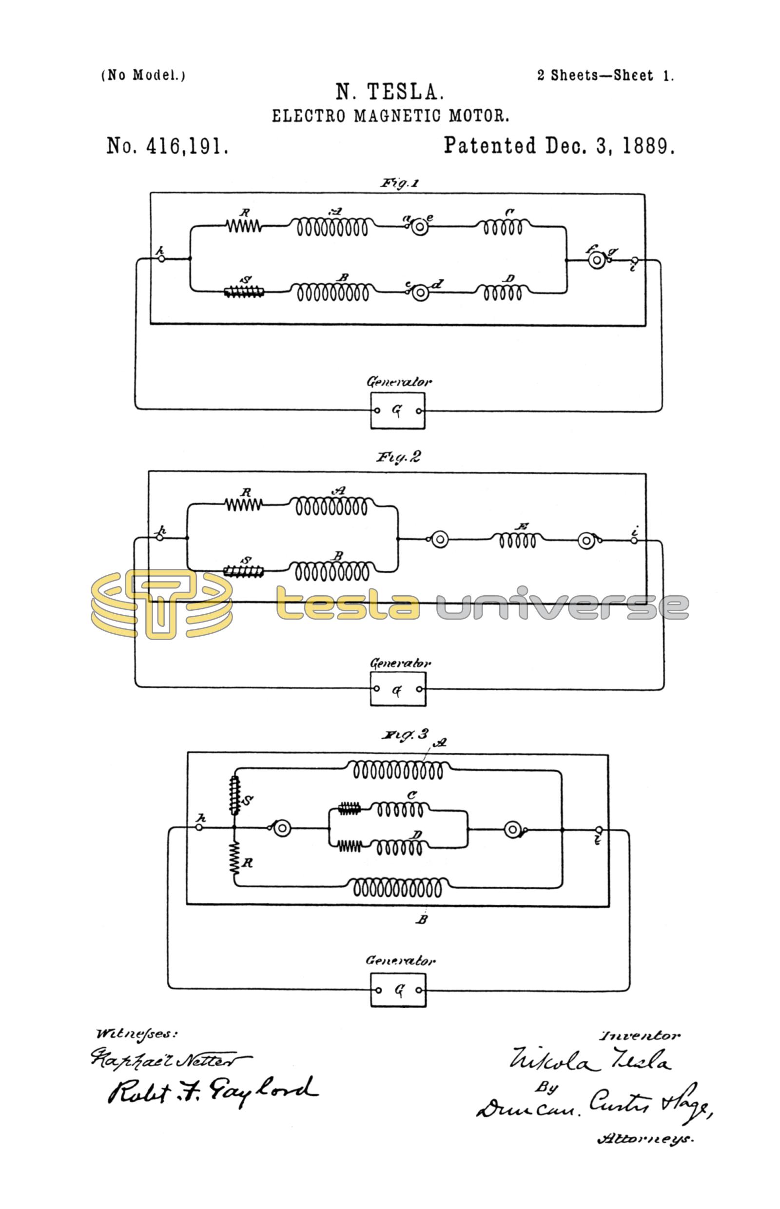
A B in Fig. 1 indicate the two energizing-circuits of a motor, and C D two circuits on the armature. Circuit or coil A is connected in series with circuit or coil C, and the two circuits B D are similarly connected. Between coils A and C is a contact-ring e, forming one terminal of the latter, and a brush a, forming one terminal of the former. A ring d and brush c similarly connect coils B and D. The opposite terminals of the field-coils connect to one binding-post h of the motor, and those of the armature-coils are similarly connected to the opposite binding-post i through a contact-ring f and brush g. Thus each motor-circuit while in derivation to the other includes one armature and one field-coil. These circuits are of different self-induction, and may be made so in various ways. For the sake of clearness I have shown in one of these circuits an artificial resistance R and in the other a self-induction coil S. When an alternating current is passed through this motor it divides between its two energizing-circuits. The higher self-induction of one circuit produces a greater retardation or lag in the current therein than in the other. The difference of phase between the two currents effects the rotation or shifting of the points of maximum magnetic effect that secures the rotation of the armature. In certain respects this plan of including both armature and field coils in circuit is a marked improvement. Such a motor has a good torque at starting; yet it has also considerable tendency to synchronism, owing to the fact that when properly constructed the maximum magnetic effects in both armature and field coincide—a condition which in the usual construction of these motors with closed armature-coils is not readily attained. The motor thus constructed exhibits, too, a better regulation of current from no load to load, and there is less difference between the apparent and real energy expended in running it. The true synchronous speed of this form of motor is that of the generator when both are alike—that is to say, if the number of the coils on the armature and on the field is x, the motor will run normally at the same speed as a generator driving it if the number of field-magnets or poles of the same be also x.
Fig. 2 shows a somewhat modified arrangement of circuits. There is in this case but one armature-coil E, the winding of which maintains effects corresponding to the resultant poles produced by the two field-circuits.
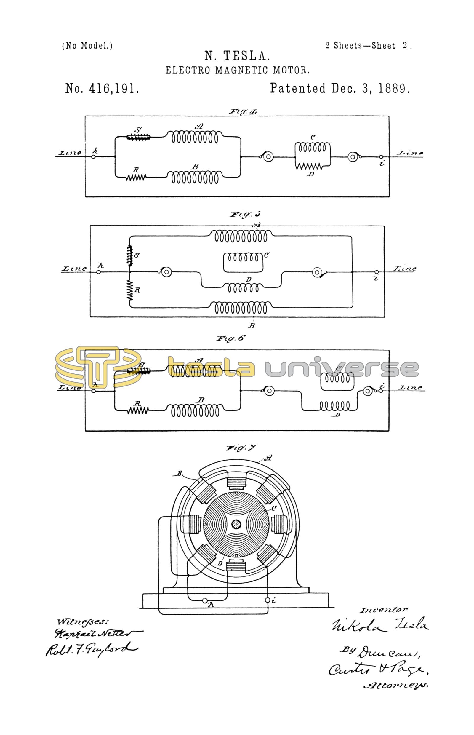
Fig. 3 represents a disposition in which both armature and field are wound with two sets of coils, all in multiple arc to the line or main circuit. The armature-coils are wound to correspond with the field-coils with respect to their self-induction. A modification of this plan is shown in Fig. 4—that is to say, the two field-coils and two armature-coils are in derivation to themselves and in series with one another. The armature-coils in this case, as in the previous figure, are wound for different self-induction to correspond with the field-coils.
Another modification is shown in Fig. 5. In this case only one armature-coil, as D, is included in the line-circuit, while the other, as C, is short-circuited.
In such a disposition as that shown in Fig. 2, or where only one armature-coil is employed, the torque on the start is somewhat reduced, while the tendency to synchronism is somewhat increased. In such a disposition, as shown in Fig. 5, the opposite conditions would exist. In both instances, however, there is the advantage of dispensing with one contact-ring.
In Fig. 5 the two field-coils and the armature-coil D are in multiple arc. In Fig. 6 this disposition is modified, coil D being shown in series with the two field-coils.
Fig. 7 is an outline of the general form of motor in which I have embodied this improvement. The circuit-connections between the armature and field coils are made, as indicated in the previous figures, through brushes and rings, which are not shown.
In the above description I have made use of the terms "armature" and "field;" but it will be understood that these are in this case convertible terms, for what is true of the field is equally so of the armature, except that one is stationary, the other capable of rotation.
I do not claim in this application the method or means of operating a double-circuit motor by making its circuits of different self-induction or in any way retarding the phases of current in one circuit more than in another, having made these features subject of other applications; but
What I claim is—
1. In an alternating-current motor, the combination, with field-circuits of different self-inductive capacity, of corresponding armature-circuits electrically connected therewith, as set forth.
2. In an alternating-current motor, the combination, with independent field-coils of different self-induction, of independent armature-coils, one or more in circuit with the field-coils and the others short-circuited, as set forth.
NIKOLA TESLA.
ROBT. F. GAYLORD,
FRANK E. HARTLEY.