Nikola Tesla Patents
Nikola Tesla U.S. Patent 577,670 - Apparatus for Producing Electric Currents of High Frequency
NIKOLA TESLA, OF NEW YORK, N. Y.
APPARATUS FOR PRODUCING ELECTRIC CURRENTS OF HIGH FREQUENCY.
SPECIFICATION forming part of Letters Patent No. 577,670, dated February 23, 1897.
Application filed September 3, 1896. Serial No. 604,723. (No model.)
To all whom it may concern:
Be it known that I, NIKOLA TESLA, a citizen of the United States, residing at New York, in the county and State of New York, have invented certain new and useful Improvements in Apparatus for Producing Electric Currents of High Frequency, of which the following is a specification, reference being had to the drawings accompanying and forming a part of the same.
The apparatus for converting electric currents of ordinary character into those of high frequency, which I have heretofore shown and described in applications for Letters Patent, has usually comprised a condenser and a circuit-controller operated by a suitable motive device and acting to alternately charge the condenser from a suitable source of supply and discharge it through a circuit of such character as to render the discharge one of very high frequency. For many purposes it has been found advantageous to construct the circuit-controller with insulating and conducting segments of equal length, so that the condenser is connected with its discharge-circuit during one-half of the time only. It follows from this that the working circuit, or that in which the high-frequency currents are developed in form for practical application, receives such currents during only one-half the time.
For certain purposes it is desirable for economical operation that there should be no cessation of the flow of such currents, and my present improvements have been devised with the object of increasing the output of a given apparatus by providing means by which, without material additions to or complication of such apparatus, high-frequency currents may be produced thereby continuously or without periods of rest.
Broadly stated, the improvement consists in the combination of two condensers with a circuit-controller of such character and so operated by a single motive device as to charge and discharge said condensers alternately, whereby one will be discharging while the other is being charged, and conversely.
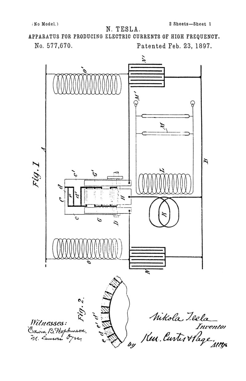
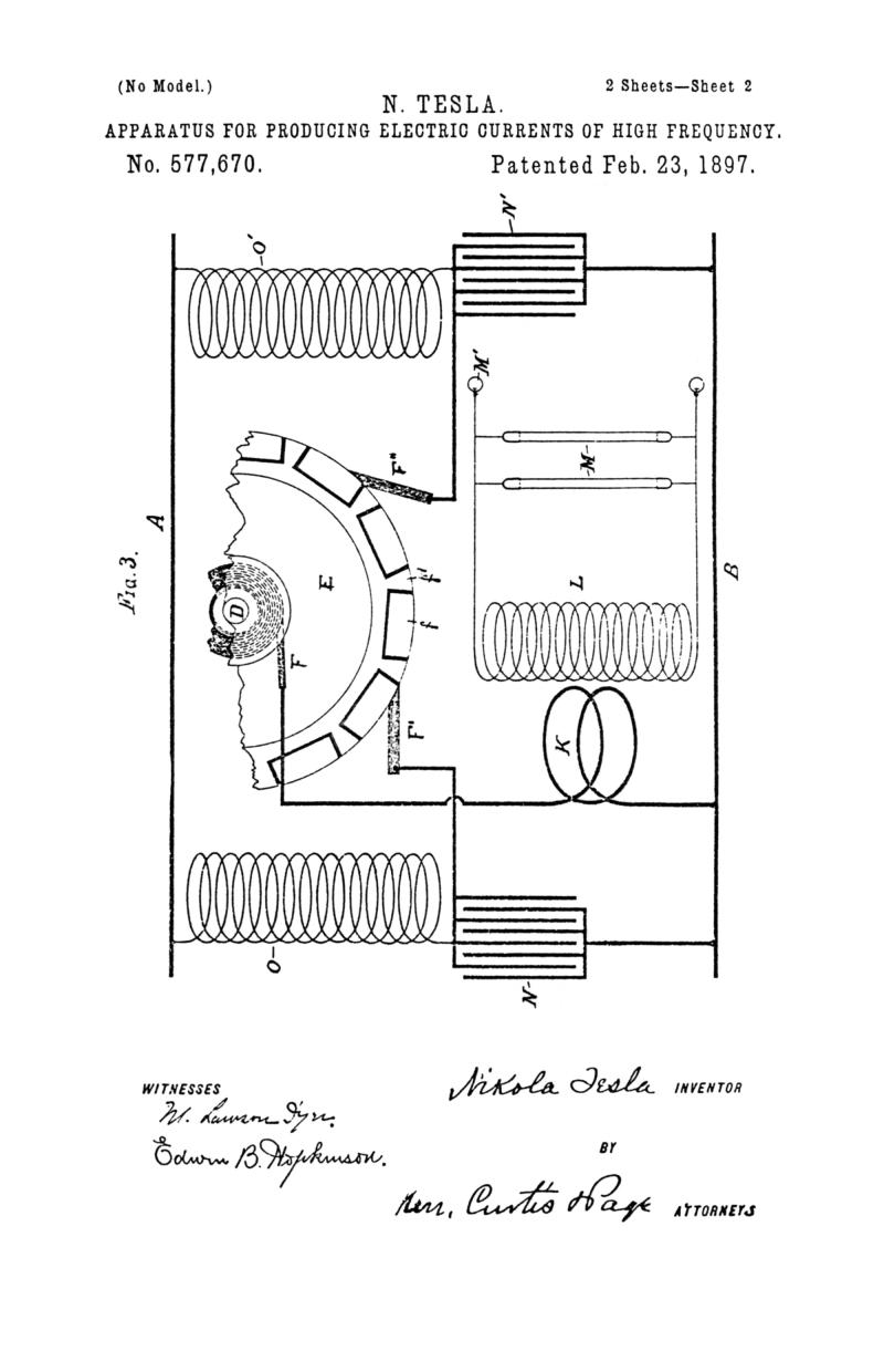
In the drawings hereto annexed, Figure 1 is a diagrammatic illustration of the arrangement and circuit connections of the invention. Fig. 2 is a sectional view of a part of the commutator employed; and Fig. 3 is a diagram similar to that of Fig. 1, illustrative of a modified embodiment of the invention.
Let A B designate the two conductors of any circuit from which the energy is derived that is to be converted into a current of high frequency.
C is a circuit controller or commutator, a portion only for convenience being shown in the figures. It is designed to be rotated by any suitable motive device, of which, however, the shaft D only is shown, and its plan of construction is as follows:
The letters c c' designate two metal heads or castings with projecting portions d d', which, when the two heads are brought together and secured to a hub or shaft, intermesh, as shown in the drawings.
The spaces between two adjacent projections or bars d d' are equal in arc to the width of one of said bars and are filled in with blocks e, preferably of metal, insulated from the other conducting portions of the device. By the interposition of mica or other suitable insulating material the two heads or castings c c' are insulated from each other. Upon the periphery of this commutator bear three brushes G G' H, the two former resting upon the continuous metallic portions of the two heads, respectively, the latter being in position to bear upon the projections d d' and blocks e alternately.
In order that the brushes may be capable of carrying any current which the operation of the apparatus may demand, they are made of large cross-section, the brush H being approximately equal in width to one of the projections or segments d d', or to the space between adjacent segments, so that in passing from one it comes into contact with the next.
The brush H is connected to the main B through a primary coil K of low self-induction in inductive relation to a secondary L, which constitutes the ultimate source of the current of high frequency which the apparatus is designed to develop and which feeds a circuit containing vacuum tubes M, single terminal lamps M', or other suitable devices. The brushes G G' are connected with the main B through condensers N N', respectively, and to the main A through self-induction or choking coils O O', these latter being used in order that the inductive discharge of the accumulated energy therein may be taken advantage of in charging the condensers.
The operation of the apparatus thus described is as follows: By the rotation of the commutator C the brush H is caused to pass over the projections d, closing the circuits through the primary K and the two condensers alternately. These two circuits are so adjusted as to have the same capacity, self-induction, and resistance. When said brush is in electrical connection with any projection d' from the part c' the circuit is closed between mains A and B through coil O', brush G', brush H, and coil K. Energy is therefore accumulated in the coil O'. At the same time the condenser N' is short-circuited through the brush G', brush H, and coil K, and discharges through this circuit the energy stored in it, the discharge being in the form of a series of impulses which induce in the secondary L corresponding impulses of high potential. When brush H breaks the circuit through coil O', the high-potential discharge or "kick" from the latter rushes into and recharges the condenser N', but as soon as the brush H has passed over the intervening block e and reached the next segment d it closes the circuit through coil O and short-circuits the condenser N, so that high-frequency currents from either one or the other of the two condensers are flowing through the primary K practically without interruption. Thus without increasing the size or power of the motive device or complicating in any material degree the commutator these devices are made to perform double duty and the output of the apparatus as a whole greatly increased. In Fig. 3 I have illustrated a modified form of commutator for this apparatus, which comprises a disk E, of metal, but insulated from its shaft. The periphery of this disk is divided into conducting and insulated segments by the insertion therein of insulated metal blocks f. The circumferential width of these blocks is three times that of the conducting segments f'. A brush F bears upon a continuous metallic portion of the disk or upon a continuous ring in electrical connection with the segments f' and is connected with one terminal of the primary K. Brushes F' F'' bear upon the periphery of the disk E and are connected to the main B through the two condensers, respectively. These brushes are capable of angular adjustment, so that they may be set to bear upon the disk at any two desired points.
From the explanation of the operation already given it is evident that when the two brushes F' F'' are set so that one leaves a segment f' at the instant that the other comes in contact with a segment f' the effect in charging and discharging the condensers is the same as in the previous instance. The capability of varying the relations of the brushes, however, which this form possesses has the advantage of permitting not only an alternate charging and discharge of the condensers, but their simultaneous charging and discharge in multiple arc, whereby the frequency of the current of discharge is reduced.
It is also evident that all phase differences in the charging and discharging of the condensers may in like manner be secured and the frequency varied within wide limits. Of course the same motor and circuit-controller might be made to charge more than two condensers in succession and to discharge them in the same order.
What I claim is—
1. The combination with a source of electric energy, of a plurality of condensers and a discharge-circuit therefore, a motive device and a circuit-controller operated hereby and adapted to direct the energy of the source into the condensers and connect them with the discharge-circuit successively and in alternation, as set forth.
2. The combination with a source of electric energy, of a motive device, two condensers, a circuit-controller adapted to direct the energy of the source alternately into the said condensers, and a discharge-circuit through which, by the operation of said circuit-controller one condenser discharges while the other is being charged, as set forth.
NIKOLA TESLA.
M. LAWSON DYER,
DRURY W. COOPER.

