Plans
Electronic Tornado - Plasma Display Power Supply
A universal power source for an Eye-of-the-Storm-like display, and other unusual plasma and neon lighting devices.
You no longer need to go to a local discotheque to see the latest in unusual lighting effects. Whether it's an Eye-of-the-Storm-like display, a Devil's Furnace, or travelling-wave neon lamps, you can now buy them for your own home at the larger department stores and high-tech boutiques. Only problem is, they usually cost big bucks - in the neighborhood of $200; but you can certainly build them for much less if you have the special kind of power supply that's needed. And that's where our universal plasma power supply comes in: it can drive all three kinds of displays - you simply connect the desired display device to the universal plasma power source.
Fire in Your Hand
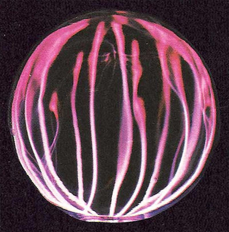
For those of you unfamiliar with discotheque lighting, we'll take time out to explain. An Eye-of-the-Storm-type plasma device is a glass bulb that surrounds a small golf-ball-size core. When powered, red and blue streamers resembling flashes of lightning emanate from the ball to the globe. If you move your fingers over the globe the streamers follow your fingers and appear to burst and mushroom at your fingertips.
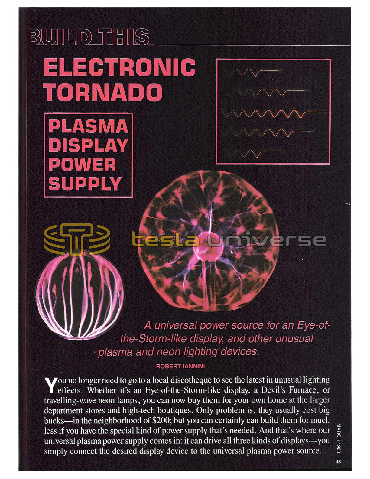
A Devil's Furnace is also a globe but there is no central ball. Streamers of flame-tipped lightning flow upward from the base and follow the curvature of the globe. As you move your hand or fingers over the globe the Devil's Flame follows them and "explode" against the bulb.
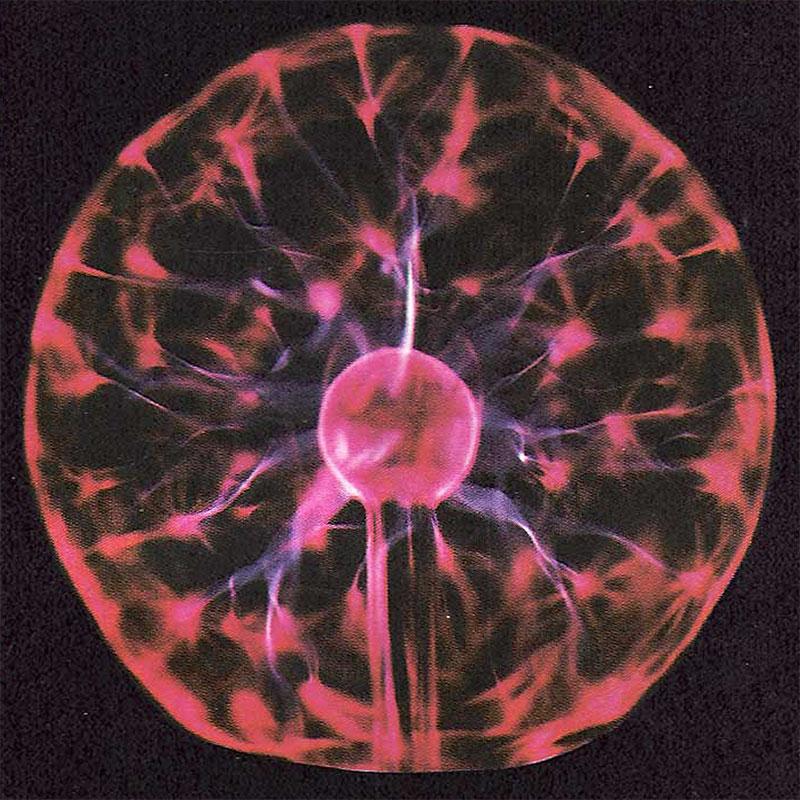
A travelling-wave or tracing neon lamp is a lighting device that illuminates slowly from end to end, then extinguishes, then repeats the cycle. The time it takes for total illumination of the tube and the repetition rate are determined by the characteristics of the power source.
Since the power source for a travelling-wave neon lamp is the most complex, that's the one we'll describe - so that you get the option of using all three devices. The circuit that determines the speed of end-to-end illumination determines the brightness range of the plasma globes, while the repetition-rate circuit for the neon tube can be easily bypassed for fulltime plasma-tube display.
The Usual Power
The usual way to power neon and cold-cathode gas discharge tubes is to use a high-voltage, current-limited transformer operating at 60 Hz that is connected to both ends of the tube; an approach that only allows the full discharge length to be simultaneously energized. Sequential energizing of the display is therefore impossible, and any display motion must be simulated by using individually-segmented discharge tubes, each having a connection to an individual source of power. Timing and power-control circuits determine the distribution of power to the individual segments of the tube.
In our universal power supply, instead of 60 Hz, we substitute high-frequency energy of approximately 20 kHz as the power source, which makes it possible to excite and reenergize the tube's gas via a connection to only one end of the tube. That is made possible by the capacitance between the ionized gas and the surroundings, which produces a low enough reactive impedance so the high-frequency energy can cause plasma ignition.
Since ignition depends on the capacitance of one end of the tube to its surroundings, it allows the ignited plasma display to travel along the tube, creating a defined bright and dark band. The degree or type of travel-effect can be a pre-programmable event that determines where the plasma ignition will start, causes the ignition to travel steadily to the end of the tube, and then repeats the electrical effect; thereby creating the visual effect of handwriting or tracing
Varying voltage levels such as those from the output of a radio or audio amplifier can also be used to vary the tracing effect or the plasma-lighting discharge-effect in step with the sound amplitude. That creates bizarre and dazzling special effects.
How It Works
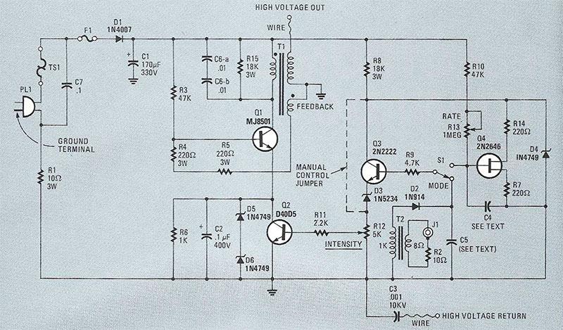
Refer to Fig. 1. The 117 volts from the AC powerline passes through thermal safety switch TS1 (which is mounted on the device's heat sink), is rectified by diode D1, and filtered by capacitor C1. Resistor R1 limits the surge current of D1 and C1. Fuse F1 is a slo-blo type that allows C1 to charge, yet opens (at 1 amp) if a catastrophic fault exists in the circuit. Thermal switch TS1 turns the device off when the temperature of Q1 exceeds 200°F. (It is necessary when operating the unit in a high-powered mode, or may be required to comply with local electrical codes.) The rectified voltage across C1 is approximately 160-volts DC.
Transistor Q1 is connected as a Hartley-type oscillator. It is biased into conduction when base current is first applied through R3. Feedback to Q1's base is obtained by a tertiary feedback winding on T1 that is in-phase with T1's primary winding. The positive feedback is what causes Q1 to oscillate. Base current is limited by resistors R4 and R5.
The resonant frequency of T1 is such that the circuit oscillates at a frequency of approximately 20-25 kHz. A resonating capacitor, C6, tunes the primary of T1 to a smooth, soft waveform, while R15 provides the load impedance that is sometimes necessary when the supply powers very small display tubes and globes.
Since the power supply uses a ground circuit that is common to the AC powerline, capacitor C3 is provided to prevent a hazardous condition should polarized line-cord plug PL1 be defeated.
The gain of Q1 determines the output voltage. The gain is controlled by the conductance of transistor Q2, which is determined by the bias applied to Q2's base through the intensity control, R12. Diode D3 prevents any offset voltage that may occur at the beginning of the turn-on cycle from turning on Q2. Capacitor C2 bypasses any high-frequency signal that might be developed across Q2, while Zener diodes D5 and D6 limit Q2's instantaneous collector-emitter voltage to 48 volts.
The control signal applied to Q2's base - which determines the instantaneous system-output voltage - is determined by the ramp voltage produced by unijunction-transistor oscillator Q4. The period of the ramp is determined by capacitor C4 and the setting of the rate control, R13. The value of C4 should be in the range of 220-1000 uF. A mid-value of 500 uF is suggested as an initial value. Although 500 uF probably will work out best for most applications, you can experiment to determine the exact value for the kind of display that you prefer.
The ramp voltage is applied through the mode switch, S1, to emitter-follower Q3, which serves as a buffer-amplifier whose relatively high input impedance isolates C4 from variable resistor R12. The voltage produced by Q3 across R12 corresponds to the ramp voltage, thereby providing a relatively linear change in Q1's power output.
Proper biasing of Q2 by R12 is the point of conduction just as the ramp voltage starts to increase. That provides a minimum or zero tube or globe display that steadily increases as the ramp waveform builds. If R12 is adjusted for a "hold off" bias so Q2's conduction does not start until the ramp is well underway, the overall period of the output voltage, and therefore the display, is reduced.
Parts List
Resistors
R1 - 10 ohms, 3 watts
R2 - 10 ohms, ¼ watt
R3, R10 - 47,000 ohms, 1 watt
R4, R5 - 200 ohm, 3 watt, wirewound
R6 - 1000 ohms, 1 watt
R7, R14 - ¼ watt
R8, R15 - 18,000 ohms, 3 watt, wire-wound
R9 - 4700 ohms, ¼ watt
R11 - 2200 ohms, ¼ watt
R12 - 5000-ohm trimmer potentiometer
R13 - 1-Megohm trimmer potentiometerCapacitors
C1 - 170 uF, 330 volts, electrolytic
C2, C7 - 0.1 uF, 400 volts, paper
C3 - .001 uF, 10 kV, ceramic
C4 - 220-1000 uF, 25 volts, electrolytic (see text)
C5 - 1 uF, 50 volts, electrolytic
C6-a, C6-b - 0.01 uF, 1 kV, polypropylene (see text)Semiconductors
Q1 - MJ8501, NPN high voltage transistor
Q2 - D40D5, NPN power transistor
Q3 - 2N2222, NPN transistor
Q4 - 2N2646, UJT transistor
D1 - 1N4007 rectifier diode
D2 - IN914 small-signal diode
D3 - 1N5234, Zener diode
D4-D6 - 1N4749, Zener diodeOther components
F1 - 1-amp, slo-blo fuse
J1 - Phono jack
PL1 - Polarized power plug
S1 - SPDT PC-mounting slide switch
TS1 - Thermal switch
T1 - Ferrite transformer (see text)
T2 - Miniature audio transformer, 8-ohm primary, 1000-ohm secondaryMiscellaneous: Printed circuit materials, insulating board, TO-3 mounting kit, 6-32 nylon screw and nut, mica washer, insulated alignment tool, wire, solder, sheet aluminum, cabinet, etc.
Note: The following parts are available from: Information Unlimited, PO Box 716, Amherst, NH 03031: An etched and drilled PC board ($5.50): Transformer T1 ($29.50): 0.01 uF, 1 kV, polypropylene capacitor ($2 each): A complete kit containing T1 and ail other components as well as the enclosure ($59.50). Add 5% of the total order for for postage and handling.
Plasma globes and custom neon tubes are available from Strattman Design, 791 Trement St. No. E517, Boston, MA 02118. Tel. 617-266-8821. Write or phone for specific information and prices.
Audio Control
An audio signal can be substituted for the ramp control voltage by setting S1 so that Q3's base connects through R9 to D2 rather than to C4. An audio signal, say from a transistor radio, that is applied to J1 will then provide the control signal for Q2, and the system's output voltage will more or less correspond to the amplitude of the audio signal.
Normally, resistor R2 isn't necessary unless the audio signal is so strong that it swamps the unit and produces an output that appears to be on most of the time. You only have to install R2 if R12 has little effect on the output when audio is used as the control signal.
As a general rule, the 1-uF capacitor specified for C5 in the Parts List will be satisfactory, but you can experiment with different values to get the plasma or neon display you prefer.
If you have no need for either automatic ramp control by Q4, or audio control via J1, then you can install the shorting jumper indicated in Fig. 1 by the dashed line connecting R8 to R12. With the jumper installed, the brightness of a plasma-bulb display, or the brightness and maximum length of a neon display is determined only by R12.
The Display
The plasma arc - the visual display - is created by the electric current flowing through the gas in the tube. In a plasma bulb, the gas can be argon, neon, krypton, or any combination thereof. The colors generated are determined by the specific kind and ratio of gasses. In a neon tube the gas is, of course, neon. When electric current is applied to the gas, the atoms become energized to a level where both electrons and positive-charged atoms are produced. They emit light spontaneously upon returning to their initial energy state. As the electric current is reduced, the display shortens because there is insufficient energy to cause further ionization. Increasing the ionization energy causes the end of the display in a neon tube to lengthen because there are a greater number of free charges. In simple quantitative terms, the number of charges produced in the tube is directly related to the input energy. A smaller-volume tube would theoretically produce a longer discharge for a given ionization energy and vice versa. (That explanation neglects the change in the dynamic impedance of the system due to a change in the volume of gas.)
Construction
Although we provide details for construction of the universal plasma power source prototype shown, keep in mind that a complete kit that includes the cabinet and all prefabricated metal parts is available from the source given in the Parts List, which is located on page 45.
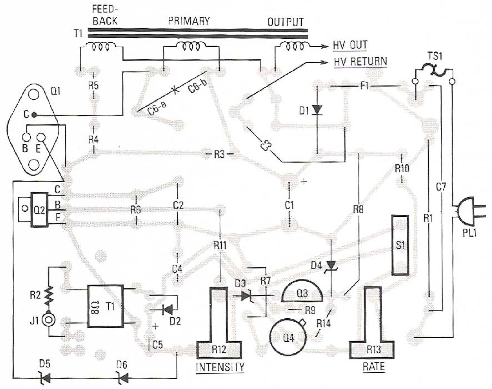
The first step is to make the PC board using the template shown in PC Service. Then, using Fig. 2 as a guide, install all board-mounted components. But note that the components are mounted somewhat differently than usual: except for D1, D3, D4, and R1, all components are mounted on end; that is, they stand vertically on the PC board. Although Fig. 2 shows diodes D5 and D6 external to the board, they actually span across the board. They are positioned about ¾-inch above the board and are located between T1 and C4.
Note that although the leads from Q2 are soldered to the PC board, during final assembly Q2 will be folded downwards so it can be heat-sinked to a metal frame. Be sure to leave sufficient lead length - about ½-inch - so the fold can be made without stressing the leads or the board.
In reality, C6-a and C6-b do not exist. There should be only one capacitor, C6, a 0.005-uF, 1-kV tubular capacitor connected across T1's primary winding. Unfortunately, that value isn't among the easiest to locate, so you can substitute the more easily obtained series-connected 0.01-uF, 1-kV capacitors, shown in Figs. 1 and 2 as C6-a and C6-b. They are both end mounted, and are connected together at the top after they are installed on the board. Finish up by using an RTV type adhesive such as G.E.'s Silicon II to cement a sheet of insulating material to the underside of the PC board.
When the PC board is completed, you can set it aside and move on to transformer T1.
A Feedback Coil
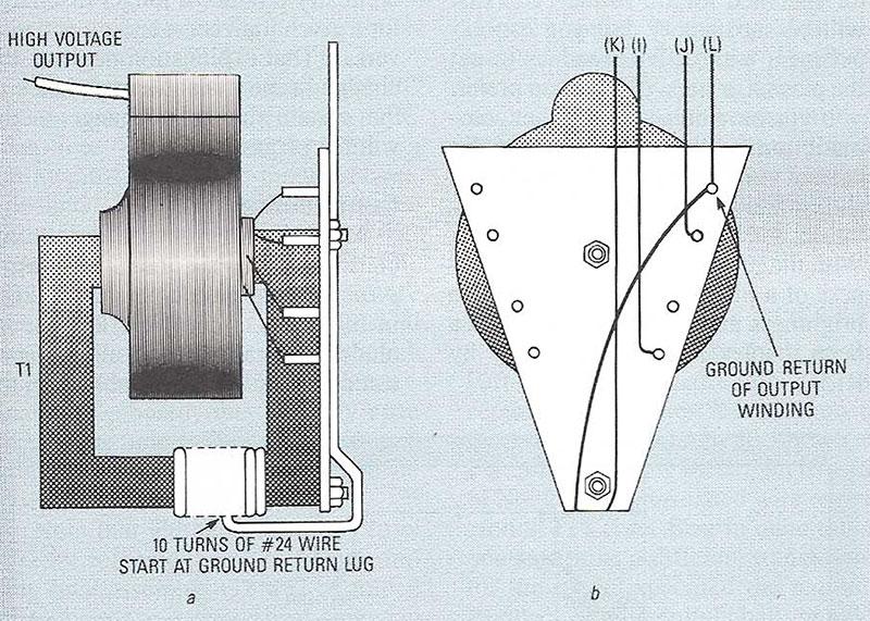
Although the T1 specified in the Parts List is supplied completely assembled, it requires the addition of feedback coil, which, as shown in Fig. 3-a, is nothing more than 10 turns of No. 24 solid, insulated wire wound around T1's core. Bear in mind that if you substitute a different transformer for the model specified the required feedback winding might have more or less turns. Also, a substitute transformer should have a primary inductance between 2 and 3 mH. If your T1 has pin connections that interfere with its installation, simply cut them short.
Figure 3-b shows letter-coding for the connections of the particular model T1 specified in the Parts List. The letters only serve as a reference when assembling the project; more on that later. (The letters are the same as those used for identification by the kit supplier given in the Parts List.)
Take note that since T1's terminals extend through its own support bracket, they must be insulated from the metal frame that is used as a chassis. The insulation can be a strip of epoxy PC material from which the copper foil has been etched. (The insulator is supplied in the complete kit of parts.)
The Frame
The metal frame chassis, which is called a mounting plate in the instructions packaged with the complete kit, also serves as the heat sink for Q1 and Q2, which is why thermal-switch TS1 is installed on the frame. If the frame gets excessively hot, TS1 opens and turns the power supply off. Since TS1 is self-resetting, it automatically restores power when the heat sink cools.
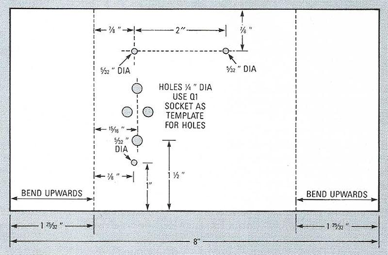
Figure 4 shows the measurements for a metal frame made from 1/16-inch aluminum. The indicated holes are for the mounting screws used for Q1, Q2, and T1. The precise layout of the diamond-pattern holes for Q1 will be determined by the particular kind of socket you use; but regardless of the kind or design of the socket, make Q1's holes ¼-inch, and deburr them with a knife or deburring tool before installing the socket.
Make certain you drill all holes before bending the side flanges upwards on the fold marks.
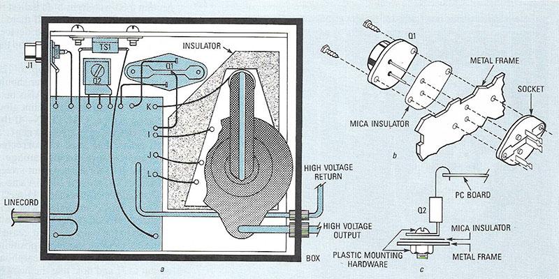
Figure 5 shows how the project is assembled. Figure 5-a shows that TS1 is secured to the metal frame with screws and nuts. If you have somehow made the frame a smidgen oversize so the mounting screws prevent the chassis from being installed in its cabinet, you can eliminate the screws and use epoxy glue to cement TS1 to the chassis. Its location is not precise, but it should be reasonably close to the top of the enclosure (away from Q2).
Figure 5-b shows how Q1 is installed on the metal frame using an insulating socket. However, note from Fig. 5-c that Q2 does not use a socket; it is insulated from the frame only by a mica insulator, so a Nylon screw and nut must be used as the mounting hardware.
Finally, use RTV adhesive to cement the PC board to the metal frame. The board must be spaced off the frame because one end is lifted by Q2's mounting; use a stack of rubber grommets for the spacers.
The Enclosure
Although the project should not be installed in an enclosure until tested, prepare the enclosure so it is ready as soon as the tests are completed. For safety, the (4½-inch wide X 4¾-inch long X 2¾-inch high) enclosure must be made of plastic; 3/32-inch thick will be ideal. (An appropriate enclosure is supplied with the kit.)
Fabricate a cover from perforated aluminum that will snap onto the top of the cabinet, but be certain to drill access holes for R12, R13, and S1 before bending the sides of the cover. Also, if you plan on using a plasma globe, assemble a base large enough to support the globe, and place the power supply within the base box.
Do not pre-size a plasma-globe base before you obtain the globe. Since plasma globes range in size from 7 to 22 inches, you must be certain the base has the proper dimensions to fully support the globe.
Checkout
Before applying power, very carefully check the insulation between the metal frame and the connections to Q1, Q2, and T1. Also, check for continuity between PL1's ground lug (the larger one) and the circuit's common (ground) point. Make certain the circuit ground is not connected to PL1's "hot" terminal.
Next, set R13 fully clockwise, R12 fully counterclockwise, and S1 so its handle points toward R10. Then connect T1's output lead to a neon tube, bank, or sign.
Plug the unit into a variable, current-metered AC supply, such as a metered variac. If that kind of equipment is unavailable we suggested connecting a 60-watt light-bulb ballast in series with the power cord. If there is a catastrophic failure in the device, the light bulb will turn on and drop the voltage at PL1 to a safe value.
Slowly turn the variac up to 120 volts and note that its ammeter should indicate only 50-60 mA. Also note that there should be only a faint glow in the neon tube. Caution - if the meter reads excessive current, a fault exists that must be corrected to prevent severe circuit damage.
Adjust R12 for a maximum sweep reading of 200 mA. At 200 mA a neon tube should energize out to 15 feet.
Adjust R13 counterclockwise and note that the neon sweep speed should increase to the point where it ceases.
Set S1 to its audio input position. Connect a transistor radio's earphone output to J1 and note that the neon or plasma display intensity should respond to the audio sound level.
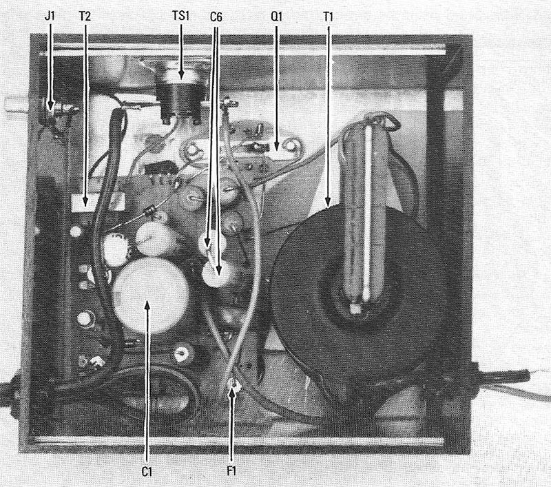
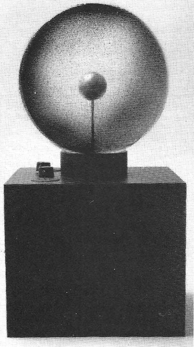
If everything checks out, install the unit in its enclosure, using strain relief clamps or devices where the line-cord, high-voltage, and high-voltage-return wires pass through the enclosure. Figures 6 and 7 show the completed prototype unit.
Special Instructions
Although the unit can power up to 30 feet of neon tubing, best results are obtained by connecting 10 - 15-foot sections in parallel because maximum sweep travel is usually limited to 15 feet.
The high-voltage-return wire is intended for connection to the end of larger neon displays. It is not necessary for single electrode-ended tubes such as used for visual audio enhancement. Do not ground the high-voltage return if unused; simply tie-wrap the wire and make sure there are no exposed strands.
Do not allow the power-supply unit to run without being connected to a display tube or globe.
Neon Displays
- Set R13 fully clockwise, R12 fully counterclockwise, and S1 to internal (so that Q3 is fed by Q4).
- Lay out the intended neon sign on a clear non-conductive bench. (Not necessary for pre-installed displays).
- Connect the high-voltage return (the ground wire) to the far end of display. Note that the wire is only used if the display does not completely ignite or is weak.
- Connect the high-voltage output (the black HV lead) to the beginning of the display. Caution: Always route that lead away from any conductive object. The lead must be short and direct.
- Set R13 fully clockwise (longest trace time). Set R12 fully counterclockwise (minimum display). Set S1 to its internal position.
- Connect the device to a polarized power outlet and adjust R12 for a full-length neon display. (It will take several trace periods to obtain the correct setting.)
- Adjust R13 for the desired speed of the trace time. Note that a point on the control will cause the system to shut down. Maximum speed occurs right after that point.
- Allow the unit to cycle for about an hour. Remove power and check the temperature of power transistor Q1. It should only be warm to the touch. If it is running hot, it may be necessary to decrease the setting of R12.
The length of the display that can be operated will vary considerably. The kind of gas, the diameter of the glass tubing, and stray capacitance can greatly effect operation. It might be necessary to experiment when energizing larger displays.
Modulation Effect
Set S1 to its audio position and feed in a signal from the 8 ohm output of a radio or a stereo. Adjust the radio's volume for a display that seems to track the intensity of the sound.
Special Note
The output energy of this device is 25 kHz at approximately 10,000 volts. For safe operation, adequate insulation of the output lead is mandatory for safe operation. Silicon or teflon insulation having a rating of at least 25 kV is recommended. Route the output lead so it isn't near any conductive objects, and splices should be sealed in high voltage putty or silicon rubber.