Plans
The Square Tesla Coil
Nikola Tesla, considered by some to be the greatest inventor of the electrical age, is today best remembered for his fascinating power-transmission experiments, using his famous Tesla Coil. In his original experiment, he was able to transmit electrical energy without wires to light incandescent lamps located over 25 miles way.
Today, most similar circuits — like the Tesla Coil described in this article — are used for educational and experimental purposes. Unlike many of the modern versions, our circuit feeds AC to a power transformer capable of outputting about 3-kV AC at 20 milliamps. The output of the transformer is sent to a primary coil, and is magnetically coupled to a secondary coil with a top capacitance. And if the primary coil is properly tuned, a spectacular high-frequency, high-voltage output is produced at the secondary coil.
Circuit Description. Figure 1 shows the schematic diagram of the Tesla Coil circuit. The circuit consists of little more than a few coils, a step-up power transformer, and a capacitor. Power from an AC wall socket is fed to transformer T1 (a small neon-sign transformer) which steps the voltage up to about 3000-volts AC.
The stepped-up output of T1 is fed through L1 and L2 across C1, causing it to charge until enough power is stored in the unit to produce an arc across the spark gap. The spark gap — which momentarily connects C1 and L3 in parallel — determines the amount of current transferred between C1 and L3.
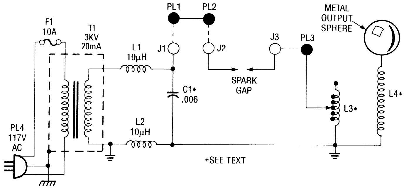
The arcing across the spark gap sends a series of high voltage pulses through L3, giving a sort of oscillating effect. The energy fed through L3 is transferred to L4 via the magnetic coupling between the two coils. (Because of the turns ratio that exists between L3 and L4, an even higher voltage is produced across L4.) Coil L4 steps up the voltage, which collects on the top-capacitance sphere where it causes an avalanche breakdown of the surrounding air, giving off a luminous discharge.
In order to get maximum output from the Tesla Coil, certain conditions must be met. First of all, the primary and secondary resonant frequencies must be made equal by tuning the primary coil, L3. That's accomplished by tapping L3 at points along the coil with a clip lead.
In addition, the setting of the spark gap greatly effects the output of the Tesla Coil. Our Tesla Coil is designed to use either a stationary spark gap or an optional rotary spark gap; both of which must be adjusted for maximum output. (We'll discuss the rotary spark gap a little later.)
If L3 and L4 are coupled too close, coil efficiency is reduced; over-coupling prevents the circuit from resonating at maximum efficiency. That also causes a breakdown between L3 and L4, which can produce arcing between the two coils, By increasing the coupling between L3 and L4, the amount of energy increases in L4 until a "critical coupling" is reached.
In addition, the Q of the coils is very important (the Q of a coil is equal to its inductive reactance divided by its resistance). The lower the Q, the higher the efficiency of the coil. The primary coil was made from a few turns of aluminum grounding wire (so its resistance is very low). The secondary has many more turns of fine magnet wire, which by its very nature exhibits a higher resistance than does the wire used in the primary coil (L3).
Rotary Spark Gap. The rotary spark gap is a simple add-on circuit for the Tesla Coil, consisting of a variable DC power supply and a small, 5000 rpm, DC motor. The circuit allows you to vary the output of the Tesla Coil by adjusting the rotating speed of the motor. A rotary gap is far more efficient than the stationary gap because the stationary gap could cut out, requiring that the gap be readjusted.
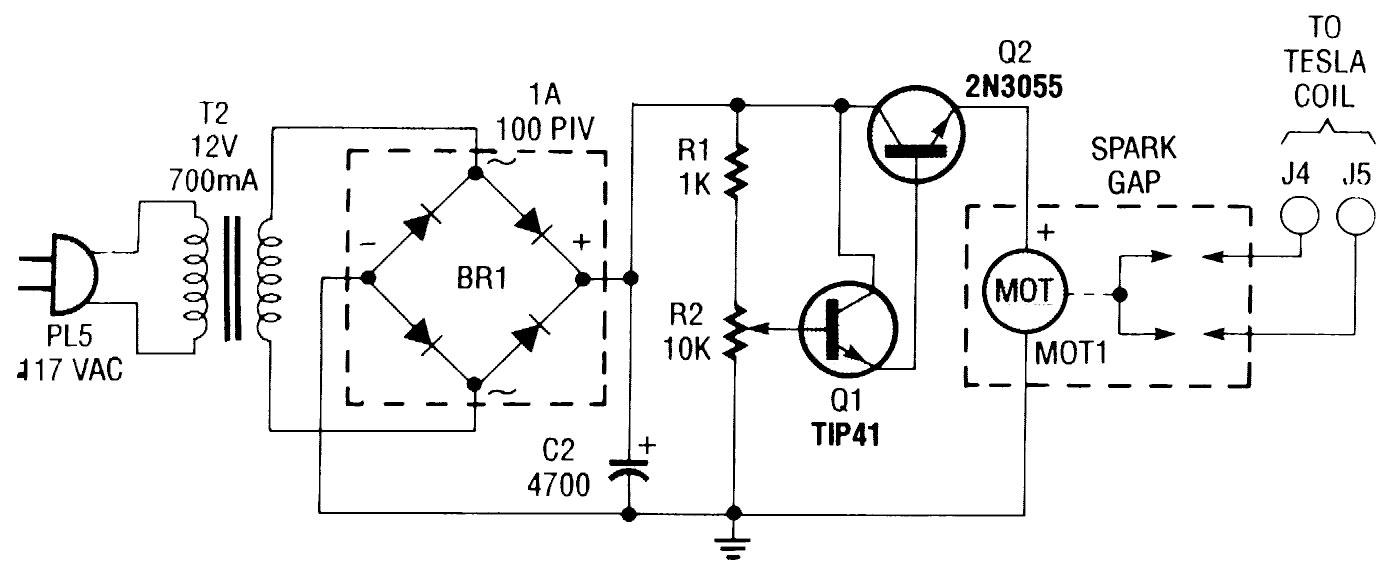
Figure 2 shows the schematic diagram of the rotary spark gap, which is assembled as a separate unit. The circuit is made up of a 12-volt power transformer, a bridge rectifier, a 4700-uF capacitor, and a 12-volt DC motor. Power is delivered to the circuit via a 117-volt AC line cord, and fed to transformer T2 (a 12-volt, 700-mA unit), which provides a 12-volt AC output. The output of the transformer is fed to BR1 (a 1-amp, 100-PIV, full-wave bridge rectifier), which converts the AC input to provide 12-volts DC for the operation of the motor.
The output of the rectifier is fed to the base of transistor Q1, which along with Q2 forms a Darlington pair. The output of Q1, which controls the bias presented to the base of Q2, is controlled by potentiometer R2. Potentiometer R2 is used to adjust the base bias on Q1, thereby varying the current through Q2, which in turn varies the rotating speed of the motor.
The rotary spark gap has a stationary post (two screws) mounted on a small square of perfboard, which face a rotor (another perfboard square on which four screws are mounted and electrically connected together with bus wire). The stationary posts and the rotor posts are positioned as close as possible. The movement of the rotor makes and breaks the gap giving maximum impulse power, and will not cut out if the stationary and rotor posts are set properly.
The rotary spark gap is connected to the Tesla Coil through separate wires and banana jacks (J4 and J5). When the circuit is powered up, the current that normally travels through the stationary spark gap on the Tesla Coil is rerouted through the rotary gap via J4 and returned to the Tesla Coil via J5. To make the connections plug PL1 into J1, PL2 into J4, and PL3 — which in Fig. 1 is used to connect the output of the stationary spark gap to L3 — into J5.
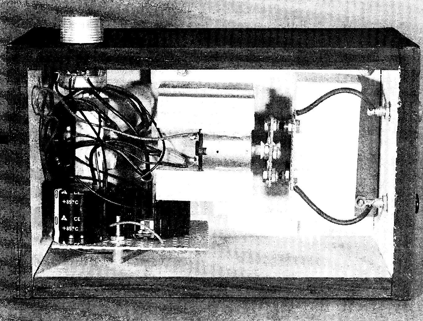
Construction. The author's prototype of the Tesla Coil was built into a large plastic enclosure; because of the high voltages involved, it is imperative that you avoid metal enclosures. Because the circuit consists of very few parts, its components can easily be hard-wired together within the housing, using Fig 1 as a guide. There is nothing particularly critical about the layout of the circuit. Just be sure to maintain adequate spacing between the individual components.
PARTS LIST FOR THE TESLA COIL
- L1, L2 — 10-uH, AC-line filter choke
- L3 — 6 turns, #10 aluminum grounding wire, see text
- L4 — 348 turns, #24 magnet wire, see text
- T1 — 3-kV, 20-mA, neon-sign transformer
- C1 — .006-uF. 5000-WVDC ceramic capacitor (see text)
- F1 — 10-amp fuse
- J1-J3 — Banana jack
- PL1-PL3 — Banana plug
- PL4 — 3-conductor AC power plug with line cord
- Metal output sphere, plastic or wooden enclosure, "L" brackets, wire, solder, wood, hardware, etc.
PARTS LIST FOR THE ROTARY SPARK GAP
- Q1 — TIP41 NPN silicon power transistor
- Q2 — 2N3055 NPN silicon power transistor
- BR1 — 1-amp. 100-PIV, full-wave bridge rectifier
- MOT1 — 12-volt, 5000-rpm, DC motor
- T2 — 12-volt, 700-mA. step-down power transformer
- R1 — 1000-ohm, 1/4-watt, 5% resistor
- R2 — 10,000-ohm potentiometer
- J4, J5 — Banana jack
- PL5 — 2-conductor AC power plug with line cord
- Perfboard materials, plastic or wooden enclosure, wood, wire, solder, hardware, etc.
Note: A 3-kV, 20-mA, neon-sign transformer (T1) is available as part number 720-391 from N. Glantz & Son. 18-218 57th St., Brooklyn NY 11220, Tel. 800-522-5120. The 12-volt DC motor for the optional rotary spark gap (MOT1) is available from H&R Corp., 401 E. Erie Ave. Philadelphia. PA 19134, Tel. 800-848-8001. Contact those companies directly for pricing, shipping and handling charges, etc.
Plans for making your own high-voltage capacitors. such as the one required for CI, are available for $3.50 postpaid from Alegro Electronic Systems, 3 Mine Mountain Road, Cornwall Bridge, CT 06754; ask for item number UHVC400.
Start by drilling holes in the enclosure to pass wires through and for the panel-mounted components. In the author's prototype, three sides of the enclosure were outfitted with appropriate sized holes. A 1/8-inch hole was drill in one side of the enclosure, through which a ground wire connects to L3.
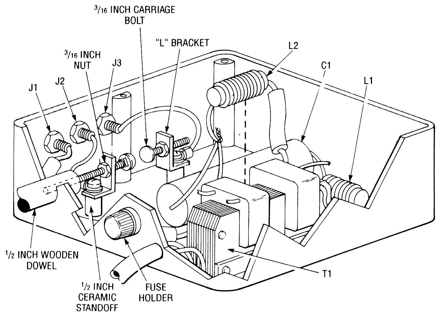
On another side of the enclosure, holes were drilled to accommodate a dowel rod (which is part of the stationary spark gap), a fuse holder, and the power cord. On the third side, three holes were drilled for banana jacks. It will also be necessary to drill holes in the bottom of the enclosure suitable for T1's mounting hardware.
Begin assembly by mounting the power transformer on the bottom of the enclosure. Next connect a 10-uH AC filter choke in series with each of T1's secondary leads, and then connect the free ends of each coil across C1 (see Fig. 1).
Note: In the author's prototype, C1 is really two .012-uF, 2500-volt AC capacitors that were wired in series to create C1 (giving the capacitor an effective rating of .006 uF at 5-kV AC). If you use the same scheme, keep the connecting leads between the capacitors as short as possible. After connecting the capacitors together, cover the gap between the two units with non-conductive tape, and connect the jerry-rigged unit in the circuit as shown.
Stationary Spark Gap. The stationary gap can be made from two 3/16-inch carriage bolts (see Fig. 3). One bolt is stationary and the other one is adjustable so that it can be used to vary the spark gap. A 1/2-inch wooden dowel is attached to the bolt that is to be adjustable, allowing adjustments to the gap to be made from outside the project's enclosure.
The wooden dowel is very important; one does not want to adjust the gap by touching metal (or any other conductive device), since the gap is adjusted with the Tesla Coil in operation.
The bolts that form the spark gap are supported by two "L" brackets mounted to spacers so that they face each other (see Fig. 3). The stationary post of the spark gap is connected to J3, and the movable bolt is connected to J2.
Primary Coil. The original primary coil (L3) was made from 6 turns of #16 aluminum grounding wire in a pancake style winding. However, to give the unit a somewhat unusual look, the original (more-or-Iess round) primary coil was replaced with a square version made from heavier #10 aluminum grounding wire. The Coil was formed on four 6-position, twin-turnscrew type barrier blocks, which were mounted on four blocks of wood.
The wood blocks (with barrier blocks attached) were mounted to the top of the enclosure near the edges, and bus wire was then connected to the barrier blocks to form the coil. Note: The wires do not have to be fed through the barrier strips because of the twin-turnscrew arrangement, The wire can be cut to the proper size and screwed into the terminal strip to form the primary coil.
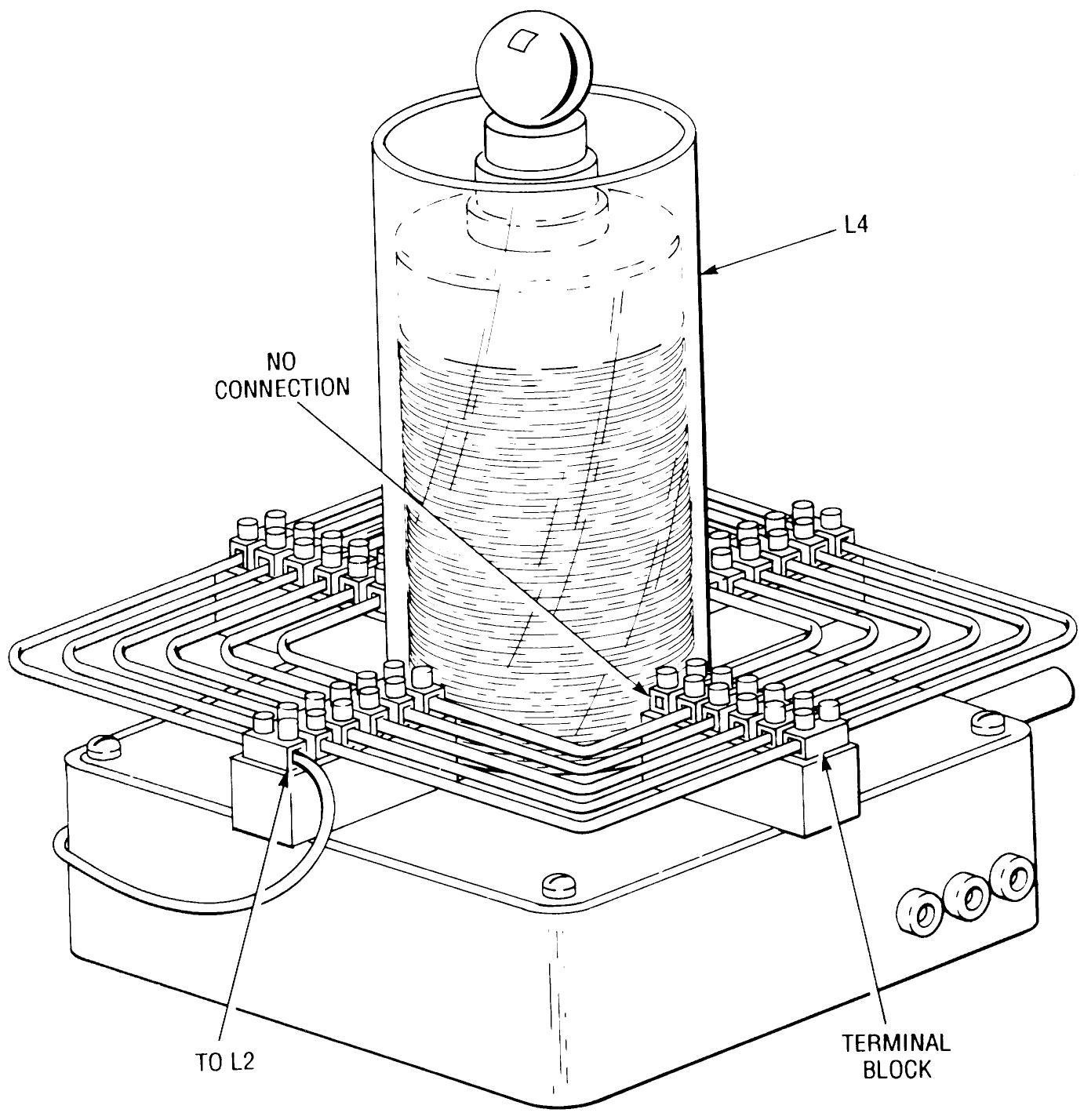
The inner dimensions of L3 should be about 6-inches square. When making the coil be careful that you do not form wire loops, instead of the continuous coil illustrated in Fig. 4. When you are finished with the coil, there should be one unoccupied screw terminal at the center and another at the outer rim of the coil. The unoccupied terminal at the outer rim of L3 is connected to ground via a wire that's brought out through a hole in the enclosure. The unoccupied terminal at the center of the coil is left floating.
The Secondary Coil. To fabricate the secondary coil (L4), the author wound about 348 turns of #24 magnet wire onto an 8 1/2-inch length of 3 1/2-inch diameter PVC tubing. That works out to be about 48 turns per inch, covering 7 1/4 inches on the PVC tubing.
The coil was wound by hand using a simple jig — which consists of little more than a stand for the wire and another for the coil form. When winding the secondary coil, try to keep the winding as even as possible without overlapping any turns.
After the coil has been wound, apply clear varnish or polystyrene (Q-DOPE) to hold the coil windings in place, and to help insulate the coil. Next drill a small hole in the center of the Tesla Coil enclosure lid, and thread the lower lead of L4 through the hole and connect it to the ground end of L3 (as shown in Fig. 1) and mount L4 in the center of L3 (see Fig. 4). The secondary coil is then secured in place with glue.
As an added measure of protection, you can also place clear plexiglass 4-inch OD (outside diameter) tubing over the secondary coil as a second layer of insulation. You might also seal the insulating tube and place mineral oil in it, thereby further increasing the tubing's insulating properties, but that's not necessary for this type of Tesla Coil.
The Output Sphere. The output sphere — a 1 1/4-inch steel ball on top of a plastic spacer — also serves as the top capacitance. An important point here is that the surface area represents the capacitance not the inner area of the ball. It matters not if you use a solid boll or a hollow ball; they will both work equally well as long as their surface areas are equal.
The size of the sphere effects the secondary's resonant frequency, so if you use a larger sphere, it will be necessary to retune the primary coil for maximum output. A bigger sphere collects more energy, causing it to give off a higher output. So experimenting with the top capacitance is highly recommended.
The Rotary Gap. The rotary spark gap is not necessary to the operation of the Tesla Coil. So, if you do not wish to build the optional rotary gap, skip this section.

The rotor of the rotary spark gap is made from a small perfboard square on which four #6 screws are mounted and electrically connected through bare bus wire. The stationary post consist of another perfboard square (of equal size), containing two #6 screws that are not tied together electrically. The screws of the stationary post are instead taken out to J4 and J5. Perfboard is specified because the holes in perfboard make it easy to align the screws on the rotor with those on the stationary post.
The first step in building the rotary gap is to build and mount the motor support. In the author's prototype (see Fig. 5), the motor mount was made from small blocks of wood assembled in a "U" shape. A wooden mount is also used to secure the stationary post in place.
The distance between the rotor screws and the stationary post screws must be as small as possible without touching in order for the unit to function properly. After mounting the motor mount in the enclosure, place the motor in the mount and secure it in position with epoxy.
Next assemble the motor controller circuitry on a piece of perfboard, using Fig. 2 as a guide. Note that T2, R2, J4, and J5 aren't mounted to the perfboard, but instead are mounted to the rotary-gap enclosure. Once the controller board is assembled check your work for wiring errors. If all checks out, solder wires to the appropriate points on the board for connection to the off-board components. Set the board to the side for now; it will be installed in a moment.
Mount the off-board components on some convenient spot on the enclosure. Mount R2 so that you'll have easy access to its wiper. Jacks J4 and J5 can be mounted in any desirable location. Before mounting T2, make sure that the transformer leads are long enough to connect to the perfboard assembly.
After mounting T2 in the enclosure, mount the perfboard assembly on the enclosure using standoffs, and then complete the wiring between the perfboard assembly and the off-board components. With that done, plug in the line cord and rotate the wiper of R2, making sure that as you do the motor speed increases and decreases. If the circuit does not operate as described, it will be necessary to recheck your work, correct any errors found, and try it again. If everything checks out, the rotary gap is complete.
Caution!!! The most important part of using the Tesla Coil is safety. Never tune (adjust the tap on L3) the Tesla Coil when power is applied to the circuit. Use a phenolic plastic box or a wooden box to house the Tesla Coil and the rotary gap — avoid metal enclosures like the plague. In addition, it is recommended that you use one hand only while working with high voltage, and wear rubber soled shoes to reduce the potential of shock hazard.
The power transformer, capacitor C1, and coils L3 and L4 must be properly grounded. You must use a 3-conductor AC power cord that is grounded (earth grounded) in the Tesla Coil itself. Do not touch the Tesla Coil while it's in operation. However if you want to show-off your creation, a fluorescent lamp may be placed near L4 to demonstrate the ionizing power of the Tesla Coil.
Only use properly rated components. Do not use an overrated power transformer. A 3-kV transformer with a 2-kV AC capacitor is out of the question. An overrated capacitor (for instance, a 6-kV AC unit) is fine in the circuit. Remember the capacitors are AC rated not DC rated.
The rotary gap will work well with this unit, but it may not work well with a larger unit. A larger unit will require that the rotary gap be redesigned. You must also protect your eyes: Do not stare at the stationary or rotary spark gaps; doing so can cause eye damage.
Operating the Tesla Coil. With the unit completely assembled, make sure that all the components are properly installed and oriented. If you are using the stationary gap, start with a gap distance of about a 1/4 inch and tune L3 at any point on the third turn from ground. At that point turn the power on; you should get an output at the sphere. Adjust the spark gap for maximum output.
Tune L3 for maximum output, by changing the position of the alligator clip with the power off. Tuning L3 and adjusting the spark gap greatly effects the output of the Tesla Coil. If you place a grounded wire near the output sphere, you should get 3- to 4-inch sparks.
If you are using a rotary gap, make sure that the screws on the rotor and the screws on the stationary post are as close as possible. Remember, the speed of the motor effects the output, so adjust the motor speed with the variable power supply.
There should be no arcing anywhere. All arcing must be corrected or you'll burn out the turns in the secondary. If L3 is too close to L4, arcing can occur. You may place a 4-inch OD plexiglass tubing over the secondary coil to help prevent arcing between L3 and L4.
Be aware that corona discharge (a bluish-purple ionization, of the air around the Tesla Coil) can cause breakdown along the secondary coil, and loss of power at the output of the sphere. Proper insulation of L4 will limit corona discharge. You may also notice an output at the top of the secondary coil coming out of the sides. That will take away from the output at the sphere, you could place several layers of tape (Turn off the power first!) around the upper-portion of L4, until the output from the sides of the Tesla Coil is reduced.
In operation, the Tesla Coil emits ozone gas, which in large quantities can be dangerous. So use the Tesla Coil in a well ventilated room, and do not operate it for periods of more than 3 to 5 minutes at a time.
In addition, the Tesla Coil emits a fair amount of Radio-Frequency Interference (RFI). Coils L1 and L2 help to limit the amount of high-voltage kickback introduced to the AC power line, and help to prevent the high voltage kickback from damaging the power transformer. Even with such precautions, RFI will still be generated at the spark gap and the output of the Tesla Coil. RFI will effect both AM radio and television reception. That's why you should not operate your Tesla Coil for more than a few minutes.
The Tesla Coil is an excellent introduction to high-voltage, high-frequency, and tuned circuits. And after building this one, you may wish to build a larger unit. The author does not recommend building a larger unit until you've learned enough about such circuits, and the safety precautions that must be followed when using them.