Plans
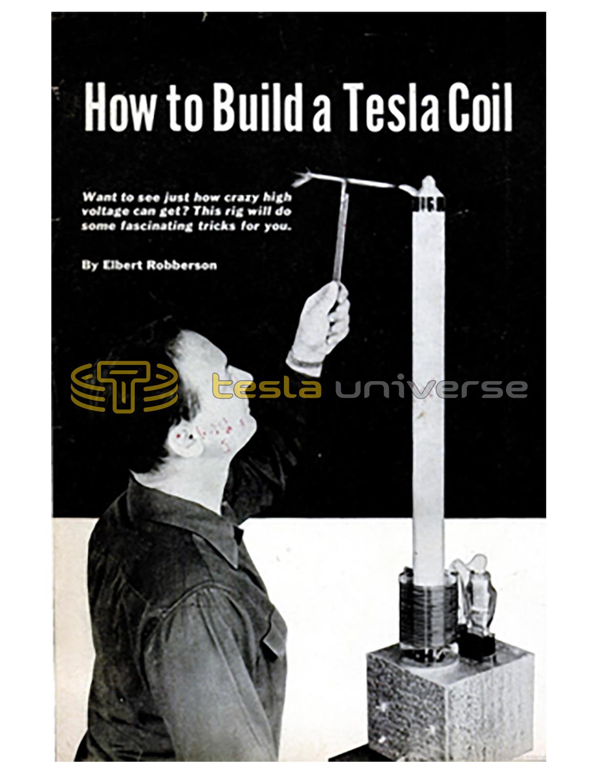
How to Build a Tesla Coil
Want to see just how crazy high voltage can get? This rig will do some fascinating tricks for you.
Have you ever let 50,000 volts jump through you?
Or seen electric flames climb a wire?
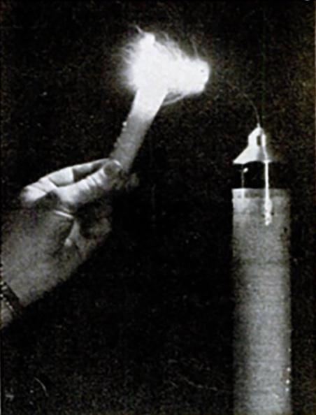
Or made a fluorescent lamp glow by holding it in your hands?
Or built an electric jet motor?
These stunts are a cinch if there is a Tesla coil in the house. One that you can build in a few evenings will do many of the tricks of a million-volt laboratory on a miniature scale.
Nikola Tesla invented the high-voltage, high-frequency transformer about the turn of the century with the idea of broadcasting electric power. It worked. From a 200-foot-high transmitter in Colorado Springs he lit lamps over a wide area without wires.
But since power was radiated in all directions, most of it was wasted. The Tesla coil went back to the laboratory.
With the age of electronics and nuclear research, cyclotrons, oscilloscopes and other inventions called for just the high-voltage radio frequencies Tesla's rig generated. The Tesla coil came off the shelf, put on working duds, and among other things took a job on television.
The Tesla coil works on the familiar transformer principle - an alternating current in one coil of wire induces a voltage in another coil insulated from but in magnetic coupling with it. A transformer can step voltage up or down. The kind used for toy trains or doorbells steps 115 volts from the house mains down to a safe 6 to 20 volts. The spark coil in a car - also a transformer - steps battery or generator voltage up to 20,000 or 30,000 so that it will jump the spark-plug gaps.
Voltage gets a big boost. The voltage change is in proportion to the ratio between. turns of the input (primary) and output (secondary) windings of the transformer. A Tesla coil has a primary of a few turns of heavy wire, and a secondary of many turns of fine wire.
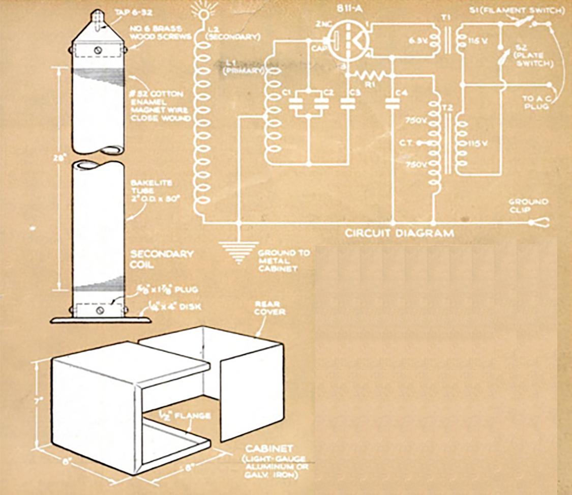
But what is fed into its primary isn't ordinary AC by a long shot. In the coil shown, for instance, household juice is first boosted to 1,500 volts by an ordinary radio plate-supply transformer. Then this is converted by a one-tube oscillator to a 475 kilocycle frequency (just off the long-wave end of your radio dial). That's what goes into the Tesla primary.
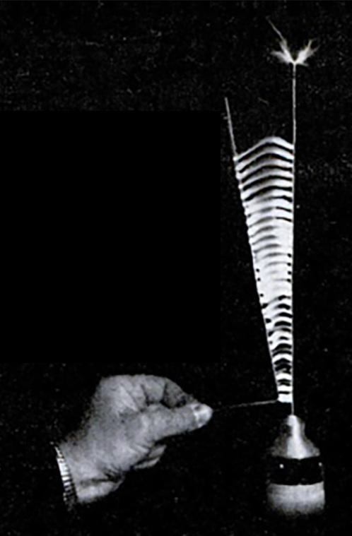
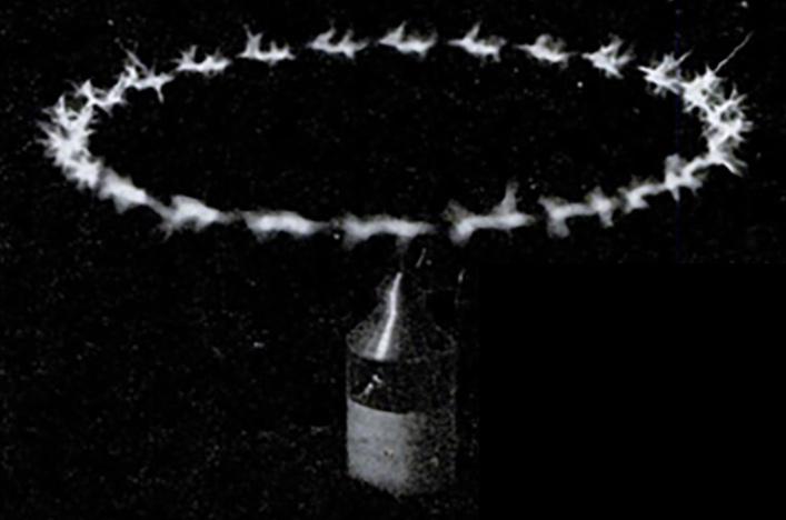
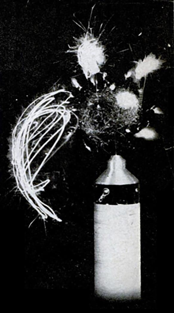
What appears on the secondary seems out of this world. You can't fence it in; it jumps off any edge or point as a fiery brush. Spectacular in appearance, this corona can create enough heat to melt metal and, if concentrated on a sharp point, generates an air blast strong enough to spin a light wheel or blow a candle flame.
It has two other weird properties-skin effect, and radiation. Household current strikes right through the human body. But Tesla currents oscillate (reverse themselves) so fast that they travel only on the surface of conductors. They go only skin deep; you don't feel a thing.
ELECTRICAL PARTS LIST
(refer to circuit diagram for symbols)L1: RF transformer primary (see text)
L2: RF transformer secondary (see text)
C1: 700 mmfd., 5,000-peak-volt mica capacitor, Sprague 2MC or equal
C2: same as C1
C3: 500 mmfd., 5,000-peak-volt ceramic or mica
C4: 5,000 mmfd., 5,000-peak-volt mica capacitor, Sprague 2MC or equal
R1: 2,500-ohm 20-watt wire-wound resistor
T1: 6.3-volt, 4-ampere, 2,500-volt insulated filament transformer, 115-volt primary, Stancor P-4019 or equal
T2: 750-0-750 volt 250 m.a. plate transformer, 115volt primary, Stancor PC-8034 or equal
S1, S2: SPST toggle switch
V1: 811-A vacuum tube
1 ceramie feed-through insulator, ICA # 2305 or equalHARDWARE LIST
½ lb. #32 cotton-enamel insulated magnet wire
50' #12 enameled copper wire
1 4-pin tube socket, Amphenol 49-RSS4
1 9/16" plate cap
1 alligator clip, ICA #884 or equal
25' #16 stranded hookup wire insulated for at least 2,000 volts
15' 2-conductor "zip" cord
1 2-pole line plug
30" length of Bakelite 1/16" wall tubing, 2" outside diameter, Insuline or equal
1 pc Plexiglas 5 1/2" by 14" by 1/8" thick
1 oz. cement for Plexiglas
1 pc 22-gauge galvanized steel or aluminum 24" by 24", or box about 7" by 8" by 8"
Miscellaneous: lugs, screws, nuts and sheet-metal screws, metallic household cement or cold autobody solder, plywood, 2" funnel
Such fast oscillations also radiate into space. They can be detected by a receiver tuned to their frequency, and will light neon or fluorescent lamps feet away. Some of these effects are shown in the photos.
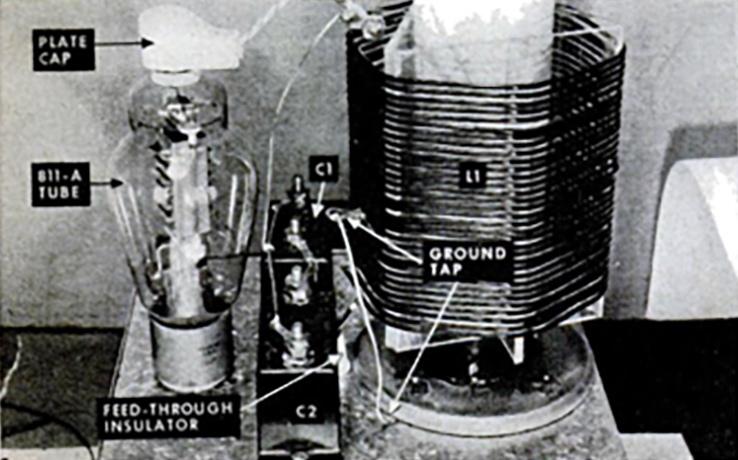
Ordinary bench tools are all you need to build the Tesla coil shown. The outfit consists of a homemade radio-frequency transformer, a vacuum-tube oscillator, and two ordinary radio power transformers for plate and filament supply. Parts are available from any amateur radio or experimenter's supply house, although the 30" length of Bakelite tubing may have to be ordered. You can save money by shopping for surplus or using scrap-box parts, but stick to the ratings and values given.
Safety is built in. Although Tesla current is harmless, the intermediate power supply can dish out a nasty jolt. Therefore the rig is designed so that exposed parts are either grounded or carry only radio frequency, which may cause a slight burn but cannot shock.
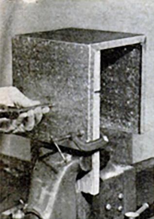
The transformers and other "hot" parts are mounted inside a sheet-metal box. You can make this from galvanized iron or sheet aluminum by bending it up as in the drawing, or use stock cabinet of similar size.
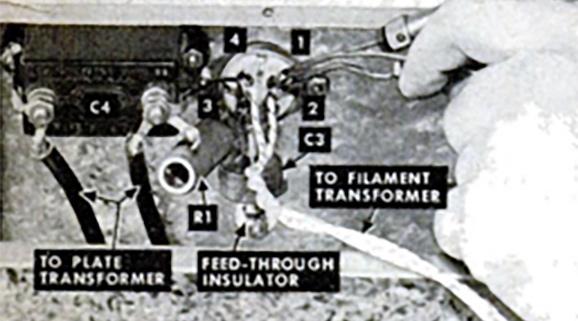
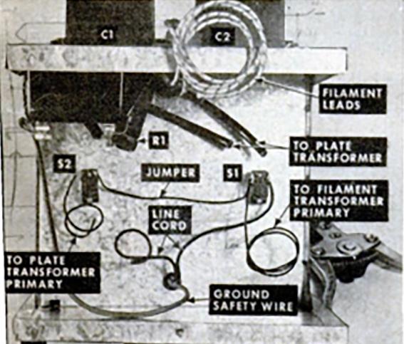
Because radio frequencies call for special handling. top-deck wiring should be No. 12 solid copper, well-soldered at connections, and kept as short as possible. Use lugs to connect wires to terminals. The inside wiring should be No. 16 gauge or heavier, with rubber or plastic-and-fabric insulation rated for at least 2,000 volts.
Brand names are given in the parts list as a help to identification. These happen to be the parts I used, but any make of equivalent quality will do.
The RF transformer. This is the heart of the Tesla coil and somewhat critical. Make no changes or substitutions if you can possibly avoid them. Since the primary coil is built up over the secondary, all operations should be in the sequence shown in the photos.
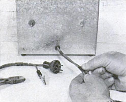
Firing up. First ground the power-cable clip, both as a safety measure and to minimize the possibility of radio interference, and plug in power cable. Insert the tube and connect its plate cap. Do not connect anything to the secondary coil terminal.
Turn on the filament switch. The tube should light. Holding a fluorescent lamp a few inches from the coil, turn on the plate switch. The lamp should glow. If it does not, turn the power off and check the wiring.
If the lamp glows, turn off the plate switch and stick a short piece of No. 12 wire into the hole in the terminal. When plate current is switched on, a crackling fistful of sparks should sprout from the end of the wire.
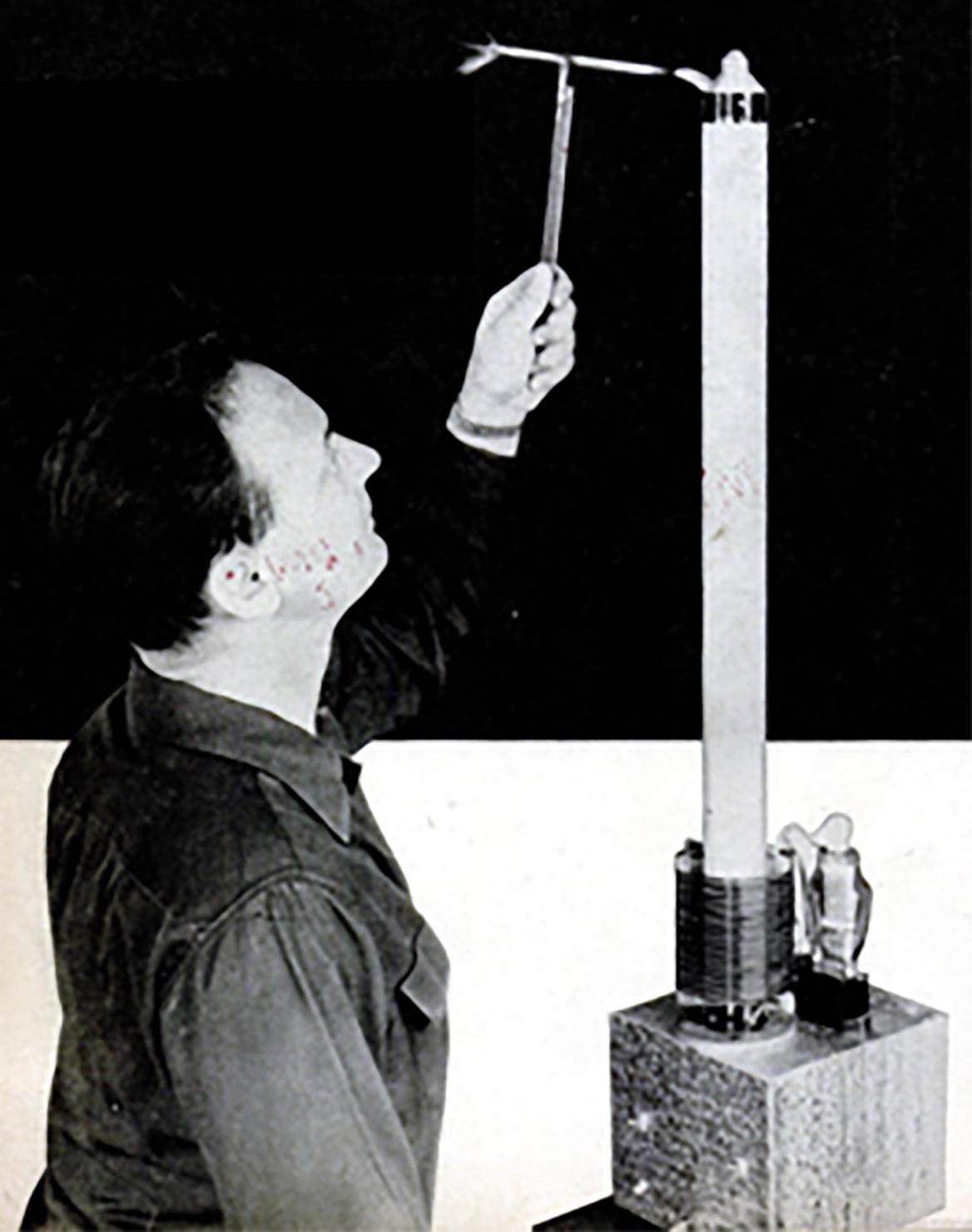
Metallic objects may be held directly in the hand and the sparks allowed to jump to the metal. Do not bring the hand itself close enough to the terminal to draw sparks; although there is no shock, they do cause small burns. Partially insulated objects should be held by a long plastic rod so that the potential will not jump through the insulation to your hand.
Trouble shooting. If the wiring is right and the tube is good but only a small spark appears, the secondary coil is probably off specifications. This means the circuits will be out of tune, and not oscillating properly. Rather than trying to doctor the coil, you can tune the circuits by juggling the value of capacitor C1, which with C2 controls oscillator frequency.
Try a value of 50 mmfd. larger or smaller than the 700 mmfd. specified for C1, and check coil action again. Odd values for C1 may be built up by paralleling several small capacitors, but they must all be of the same voltage rating. Continue altering C1 until the healthiest corona is obtained.
The plate of the tube may glow dull red. This is normal and no cause for alarm. But if prolonged operation brings the plate up to an orange or yellow glow, the plate switch should immediately be turned off and the tube allowed to cool, with the filament left on. If the tube tends to overheat constantly, change the grid resistor to one of 5,000 ohms.
Keep off the air waves. Since the Tesla coil shown is sharply tuned to a frequency off the broadcast band, it should cause less interference on radio and television than an arc welder, electric shaver or other sparking device.
However, harmonics or stray frequencies may cause a buzz at certain points on the dial of a radio placed only a few feet away. Moving the radio or the coil a short distance may clear this up.
Connect only small objects to the high-voltage terminals. Avoid large plates or long wires, as these radiate excessively, and may cause radio interference, besides stealing power from the corona effects. Be sure you always ground the power clip before switching on the unit.