Plans
The Tesla High Frequency Transformer
A unique demonstration of electrical resonance for the experienced hobbyist.
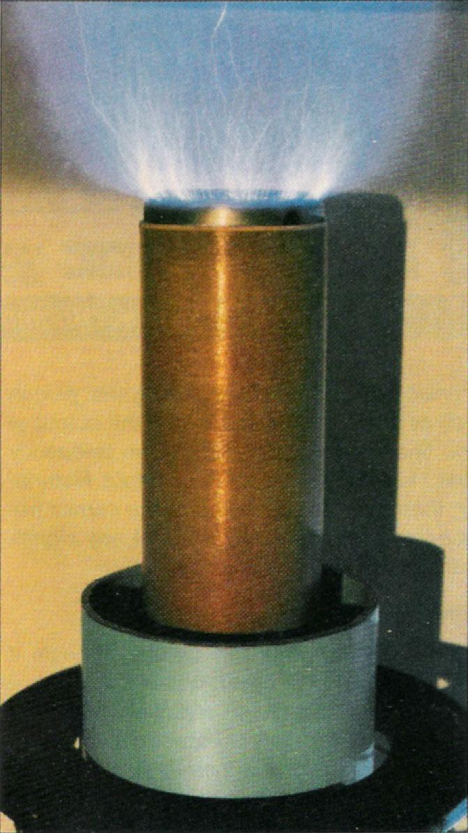
The spark-excited Tesla high-frequency transformer provides a display that leaves most first-time observers wide-eyed and speechless. Although it won't find too much use in the hamshack, it provides such an awesome demonstration of electrical resonance that one would make an ideal ham club project. The working of a transformer offers a unique visual aid for teaching a new ham candidate resonant circuit theory as he observes a crackling eighteen-inch spark discharge itself into the air.
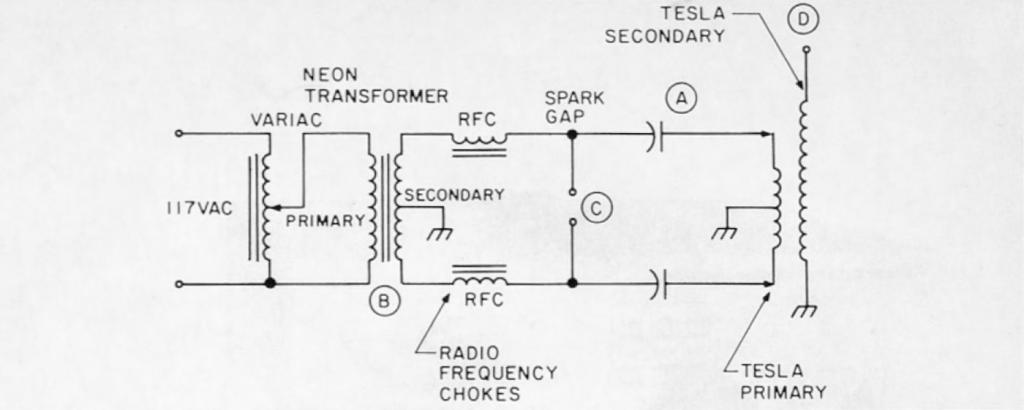
Just to refresh your memory, a Tesla is a unit of magnetic flux. My first coil was built around a commercially available neon sign transformer. These units are usually rated around 30 to 120 mA and come in various voltages. A 7500 to 15000 volt unit is perfect for a 30-inch coil and will produce a corona anywhere from 12 to 20 inches in length. These transformers can usually be found at scrap metal yards or pulled from discarded furnaces. Mine was a surplus unit given to me by a local ham. Referring to Figure 1, the Tesla's secondary may be considered a transmission line of 1/4 wavelength. As the capacitors (A) are charged by the neon transformer's secondary (B) their voltage breaks down the spark gap (C) causing the capacitors to discharge through the Tesla's primary in an oscillatory fashion. The Tesla secondary is made resonant with the primary so that the excited primary causes the secondary to oscillate in resonance. This in turn generates a high voltage with sufficient magnitude to cause a corona spark discharge at the secondary's top electrode (D).
Construction
After you have acquired the transformer, begin work on the Tesla secondary. Locate a 30-inch length of PVC (or similar material) sewer pipe about 6 inches in diameter. This material must have good dielectric properties. Beware of materials that could melt or carbonize due to arcing. The pipe should then be taken to a shop or fellow amateur who is equipped with a lathe since the tube must now be trued and threaded its full length with 20 shallow threads per inch. These grooves will serve to hold the secondary winding which is wound with one continuous length of #26 or #28 cotton or enameled wire. Ideally, this winding would be applied while the tube is still on the lathe, while the operator feeds the wire from a spool onto the grooves. In my case, I rigged up a small motor with a reduction gear to rotate the tube while I applied the winding. This was necessary since my tube was turned on a lathe out of town.
After the winding is completed the entire coil is given 3 or 4 coats of shellac and allowed to dry between coats. This prevents arcing between adjacent windings. A 6-inch gong from an electric bell or, as in my case, an aluminum ashtray, make a good top electrode. Drill a small hole in one end of the secondary and pass the last few inches of the winding through the hole to the inside of the tube, where it is soldered to the underside of the top electrode. The electrode is then glued with silicone seal to the top of the secondary's form. The Tesla secondary is now complete.
The Tesla primary consists of approximately 8 turns of #6 gauge copper ground wire which is commonly available at most hardware stores. About40 feet will be needed for our purposes. This wire is wound onto a wooden form, the construction of which I will now describe.
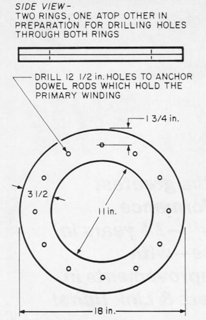
Begin construction by cutting two identical wooden rings from a 1/4 sheet of 3/4 inch plywood. The outside diameter of these rings measures 18 inches, while the inside diameter measures 11 inches — thus the width of any given part of the ring is 3 1/2 inches. I cut my rings with a common hand sabre saw. When both rings are completed, place one atop the other and temporarily screw them together in alignment.
Next, mark and drill twelve 1/2 inch holes through both rings at 1 3/4 inch centers from the outer ring edge. These holes are equally spaced around the rings (see Figure 2). Now cut twelve 1-foot lengths of 1/2 inch diameter wooden dowel. When this job is finished, insert the 12 lengths into the holes previously drilled into one of the rings. You will now have one ring forming the base of a cage with 12 rods sticking up into the air. Now place the second ring on top of the form and gently tap the top ring into place with a mallet. White wood glue should be used on all dowel ends. You should now have a kind of round wooden cage on which you will wind the primary coil. When the woodworking is complete, give the entire assembly 2 or 3 coats of shellac, allowing each coat to dry before applying the next. Now take the length of #6 copper wire and wind onto the wooden form about 8 or 9 turns spaced about 1 inch between windings.
If the windings are applied tightly, the coil will stay put without any coaxing; however. if loosely applied, you will probably need to tape the windings into place with electrical tape. I don't really recommend the latter procedure. I anchored each end of the primary with plastic tie-wraps. Alligator clips will be used later to apply power to the primary because they are easy to adjust when tuning the Tesla transformer. With the completion of the primary, you are now 90% home!
Circuit Details
Depending on the rating of the transformer you use to furnish the power, you will need to do a little figuring in order to find the required capacity value. First. divide the transformer's secondary voltage by the power rating. For example, my transformer secondary was rated at 7500 volts @ 30 mA, thus E/I implies an impedance of 250,000 Ohms. You will need to plug this value into the following formula to find the capacitor's value:
C = 1 / 2 pi x F x R
Where C equals capacity in farads
F equals Frequency (60 Hz)
R equals impedance (from the former calculation)
My circuit required a capacity of .01 uF. Because neon transformers have a center tap on the secondary grounded to the case, a symmetrical primary circuit balanced to ground is required. Consequently, two .02 uF capacitors connected in series must be used to get the .01 uF value.
Capacitors must be of the high voltage type — either mica or oil-filled surplus types may be used. The operating voltage on my oil-filled types were rated at 8000 volts. You can make capacitors from glass plates covered on both sides with tinfoil. However, in some applications the heat generated may crack the glass and blow the capacitors along with the transformer. Alternatively, double sided copper clad circuit board with the outer edges etched away to prevent arcing might be another possibility. Although I have not personally gone this route, I would be more than happy to hear from anyone who has tried this method.
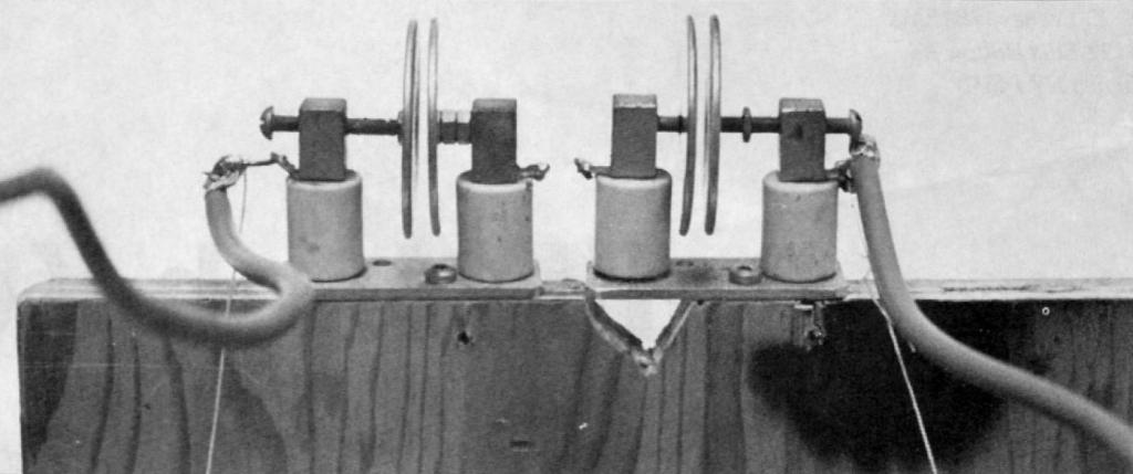
To keep damaging high frequency currents out of the neon transformer's secondary, where they could break down the insulation on the windings, pi wound radio frequency chokes must be used. These can also be made by winding small, empty wire spools slipped onto a spare piece of wooden dowel. Refer to the circuit diagram for placement of these chokes. A spark gap can be made from 4 parallel copper plates about 2 inches in diameter. I used two adjustable capacitors from an old transmitter. The capacitors consisted of two round metal disks which could be adjusted for spacing. I used two of these capacitors in series to form my spark gap. It functions very well. A method of adjusting the gap size is required to trim the frequency during tuning up of the Tesla coil.
Hooking It All Up
After you have completed both primary and secondary and acquired all other parts, start hooking the Tesla coil together. Find a spot where the coil will not be disturbed — my Tesla coil is permanently installed in my basement, away from the probing hands of my two year old daughter. A few words of warning are in order here: The voltage you are about to work with here is very dangerous. Be extremely careful. A neon sign transformer with a secondary rated at 15,000 volts at 120 mA could easily provide a fatal shock.
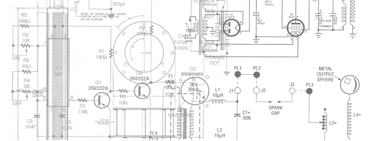
Place the primary on some non-conducting material. My coil sits on top of a table covered with formica. Next, place the secondary in the center of the primary. The bottom end of the secondary and the midpoint of the primary are connected together. This point is also connected to the case of the neon sign transformer. Connect the two radio frequency chokes to each side of the neon transformer's secondary, the other end of the chokes connect to the spark gap. The capacitors are then connected in series with the Tesla's primary and spark gap. Check the diagram for clarity on this point.
A variac must be used to slowly bring up the power on the neon transformer's primary. Otherwise, switching the unit on to the line at the wrong part of the cycle could cause the switching transient to double the voltage and blow capacitors. My coil uses capacitors with a voltage rating which is twice that of the primary circuit, so I do not use a variac on my system. Set the gaps on the spark gap plates to about 1/8 inch on each gap, then, using alligator clips on the power leads, to the Tesla primary. Tap onto the primary at about 2 turns in from the end of the winding. When you are sure everything is connected correctly, plug in the power and bring up the variac slowly. At this point a loud crackling noise will become evident as the primary circuit spark gap breaks down, the spark from this gap should be blue and bright.
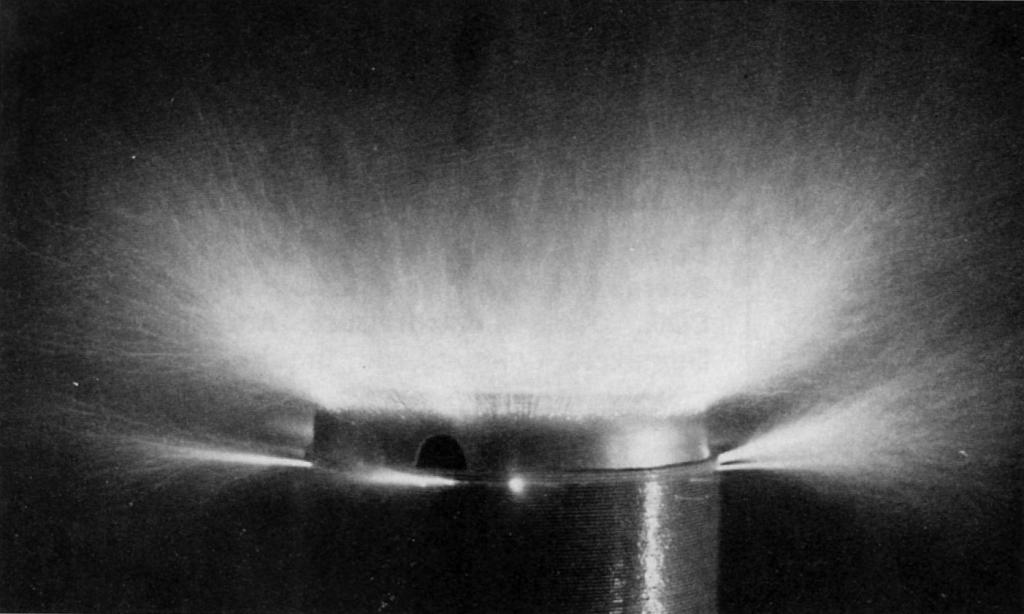
With the lights turned down, a corona at the top of the secondary should be plain to see. Further adjustment to 1/8 turn on the Tesla primary should bring improved results. You will also find that fine adjustment of the spark gap also leads to improved results, since the gap has some effect on the frequency of operation. In some cases the bottom end of the secondary must be wrapped in polyethylene to prevent discharge between the primary and secondary. I had no problems bringing my Tesla coil to resonance with the hit and miss method. However, for those with a signal generator and oscilloscope, one can tune up the system more scientifically.
For those readers with such equipment, you can tune up the coil as follows: First, isolate the secondary and place a few loose turns of wire around the bottom of the secondary and connect this wire to a signal generator covering 150-450 KHz. Next, connect the top electrode to the vertical input of an oscilloscope through a 1 megohm resistor. Take the bottom connection of the secondary and hook it to the ground terminal of the scope. Adjust the frequency of the signal generator until the rising signal amplitude of the coil's self-resonant frequency is observed. If you built the secondary according to the plans in this article, you should find the self-resonant frequency to be around 380 KHz. The primary coil must resonant with the secondary, so it must be tuned also.
To tune the primary, the spark gap must be shorted to effectively put the capacitors in parallel with the primary. Connect the oscilloscope across the primary and inductively couple the signal generator to the primary. The signal generator is generating the same signal used to detect resonance in the secondary. Adjust the alligator clips on each side of the primary's center tap until resonance is observed on the scope. The secondary's form should not be anywhere near the primary for this operation.
Start the Show
My Tesla coil is put into operation whenever guests or nephews arrive at my home. It has also been demonstrated at our local college for the electronics and physics departments. The reaction is always the same. The sight of lightning bolts close up, made on demand, is really something to be seen.
