Plans
Tesla Apparatus and Experiments Page 2
Practical Electrics - November 1st, 1921
oscillating circuit in which the high frequency currents are developed under the action of the repeated charging and discharging of the high tension condenser. The Oudin coil, therefore, does not raise the frequency, for this is already taken care of by the oscillatory circuit just described, but the voltage of the circuit, as the current passes through the primary of the Oudin coil, is intensified several dozen times by auto-transformation, so that a uni-polar high frequency, high voltage discharge radiates from the metal ball connected at the top of the secondary, as shown. This uni-polar discharge is caused by the current endeavoring to find its way to ground or, in other words, to complete the circuit, and some experimenters prefer to ground the primary and secondary lead it “X”, as shown in the diagram.

On the small kick-coil high frequency (Violet ray) apparatus sold on the market today, the flaming discharge, several inches in length, which takes place between the movable and fixed electrodes, passes across the space between the terminals X and X-1. When you hold out your hand and allow the spark to jump from the single brass ball terminal, this terminal is connected to the free end of the secondary, as shown in Figs. 1 and 2. The glass applicator or electrode supplied with the well-known Violet Ray apparatus, which is constructed on the same principle as the apparatus here described, is connected to the free terminal of the secondary of the Oudin. The body acts as a large condenser or capacity and sparks consequently jump between any part of the body and the electrode terminal of the Oudin secondary coil.
The bottle Oudin coil is constructed after the manner shown at Fig. 1. Any size bottle may be used, but a one quart wine bottle makes a very good form on which to wind the coils. The secondary winding should comprise one layer of No. 34 enameled copper magnet wire, wound preferably with a thread between the turns, the thread and wire being easily wound on together. It is well to give this layer of wire several coats of shellac, but if the secondary is to be encased in wax, or better sulphur, as indicated at Fig. 1, this will not be necessary. A layer of paraffine or a mixture of paraffine and beeswax 1" thick, or sulphur, should be molded over the secondary by placing the bottle and it's winding inside of a circular cardboard form, large enough to insure a 1" layer of insulator even all around.
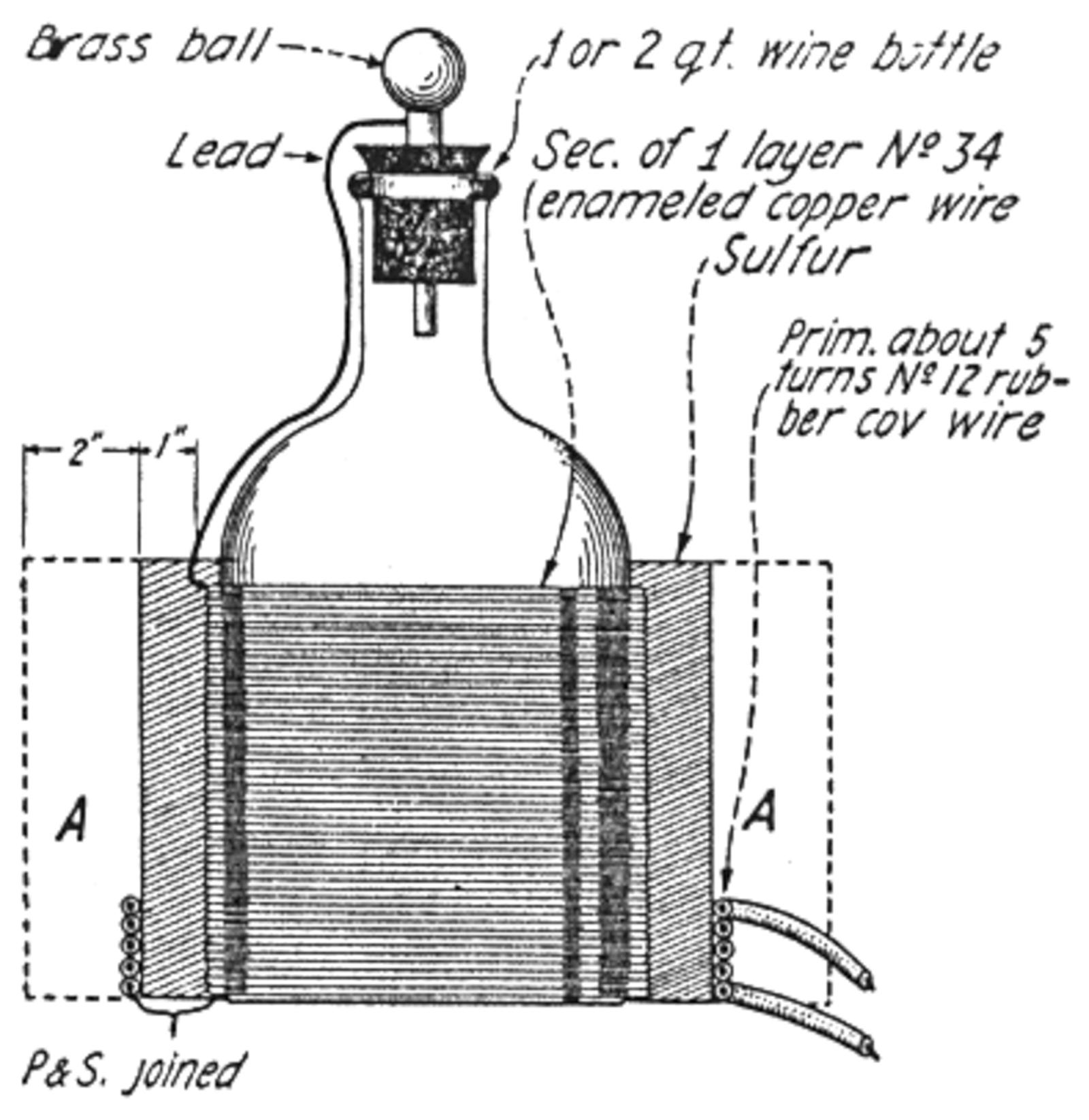

When this has hardened, the cardboard or other form may be removed and the primary coil is wound around the base of the insulator wall. This will usually require four to five turns of No. 12 rubber-covered copper wire, such as is used for electric light wiring. The best number of turns in the primary and their arrangement should be experimented with in connection with the Leyden jar or glass plate condenser to be used with the transformer at hand; and the primary turns adjusted until the maximum length of spark is obtained from the Oudin coil. In testing the length of spark produced, hold a pair of pliers or other metal in the hand and allow the spark to jump from the end of the metal to the ball at the top of the bottle. Practically no shock will be felt in this way, and the length of the spark can be easily and accurately judged.
After the proper number of primary turns for your particular outfit has been ascertained, it is best to make another mold of cardboard or tin, and mold sulphur about 2" deep all around the Oudin coil, as high as the secondary winding, and it will be best to let the sulphur extend about 2" below the bottom of the bottle, to prevent leakage of the high voltage current.
The primary and secondary are always joined together in operating a high frequency transformer, as an Oudin coil, and care should be taken to see that direction of the windings are such that the current passes around the primary and secondary always in the same direction when the two coils are joined, as shown at Fig. 2. One can soon tell whether this connection is correct or not by simply reversing the primary coil leads, when operating the high frequency set; the connection that gives the longest discharge from the Oudin terminal is the proper one.
The higher the frequency, the less shock will be felt from any apparatus of this type. The frequency is lowered by increasing the size of the condenser, lengthening the spark gap, or adding to