
Plans
A Tesla Coil
Demonstrate high voltage principles with this unit; corona discharge, ionizing gas tubes and lightning.
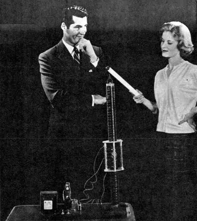
Few electrical phenomena are as startling as the hissing blue corona discharge from a Tesla coil. When bystanders see an unconnected fluorescent lamp held in your hand light up brightly, their astonishment knows no bounds. These, and other tricks such as a steel wool St. Elmo's fire and artificial lightning to a hand held screwdriver, make this high-efficiency Tesla coil a fascinating and educational project.
Invented by Nikola Tesla about 1886, the device that bears his name is really a transformer operating under rather special circumstances. Instead of using 60 cycle alternating current, the primary winding is supplied high-frequency AC (in this model about 300,000 cycles per second). The primary has relatively few turns of heavy wire. Coaxial with the primary is a secondary coil containing many, many turns of fine wire. Thus, to start with, the arrangement constitutes a step-up transformer with a large secondary-to-primary turns ratio. But this in itself cannot produce the startling effects mentioned earlier. For proper operation the secondary coil must be so constructed that it will resonate with its own distributed capacitance and the stray capacitance of the circuit at the primary frequency. When this happens, the voltages developed across the secondary winding become truly phenomenal.
Among the features that make this Tesla coil construction unique are: (1) a sliding primary coil makes up for winding errors by tuning the system to resonance without the need for a secondary capacitor. When correctly positioned, the primary induces enough voltage in the secondary to produce four-inch corona sparks. (2) once a Tesla coil is built, there is always a transportation and storage problem due to the long secondary coil. In this model, both the secondary and primary coils are demountable; the secondary is actually a plug-in coil, while the primary leads are connected to the oscillator circuit via color-coded banana plugs and jacks. So - take it apart in seconds to transport it to the place it is to be demonstrated, or to store it on an ordinary, shallow shelf.
The first step in construction is preparing the secondary coil.
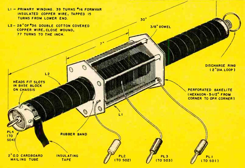
A cardboard mailing tube 2 inches in outside diameter and 30 inches long is suitable as a secondary coil form. (Bakelite tubing was used in the model because of its greater rigidity, but cardboard is just as good.) Prepare the mailing tube by giving it at least two coats of spar varnish, letting it dry 24 hours between coats. Obtain a 2 lb. roll of #36 double-cotton covered copper wire and, starting 1 inch from either end, start the secondary coil of close-wound turns. #36 d.c.c. wire gives you 77 turns per inch and you have 28 inches to wind all told making a total of 2156 turns (a little over 1100 feet or 1/5 of a mile of wire). There's no need to count the turns; merely close-wind the full 28 inch stretch. Unless you use a lathe for the purpose, you had better count on several sittings to complete the winding. Keep a heavy rubber band handy to hold the final turns in place at the end of each sitting.
When the winding is complete, apply several coats of shellac or varnish to hold the turns firmly seated on the coil form. Cut two plugs of 2 or 34 inch stock to fit in the ends of the coil form; drill each plug in its exact center, one hole to take a standard banana plug and the other for a top binding post. Pass the ends of the secondary winding through two fine holes at each extreme and solder the ends to the banana plug and binding post, respectively. The secondary coil is now finished.
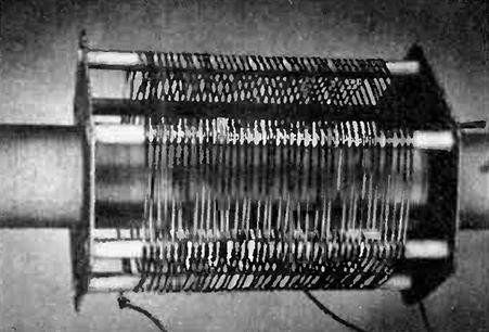
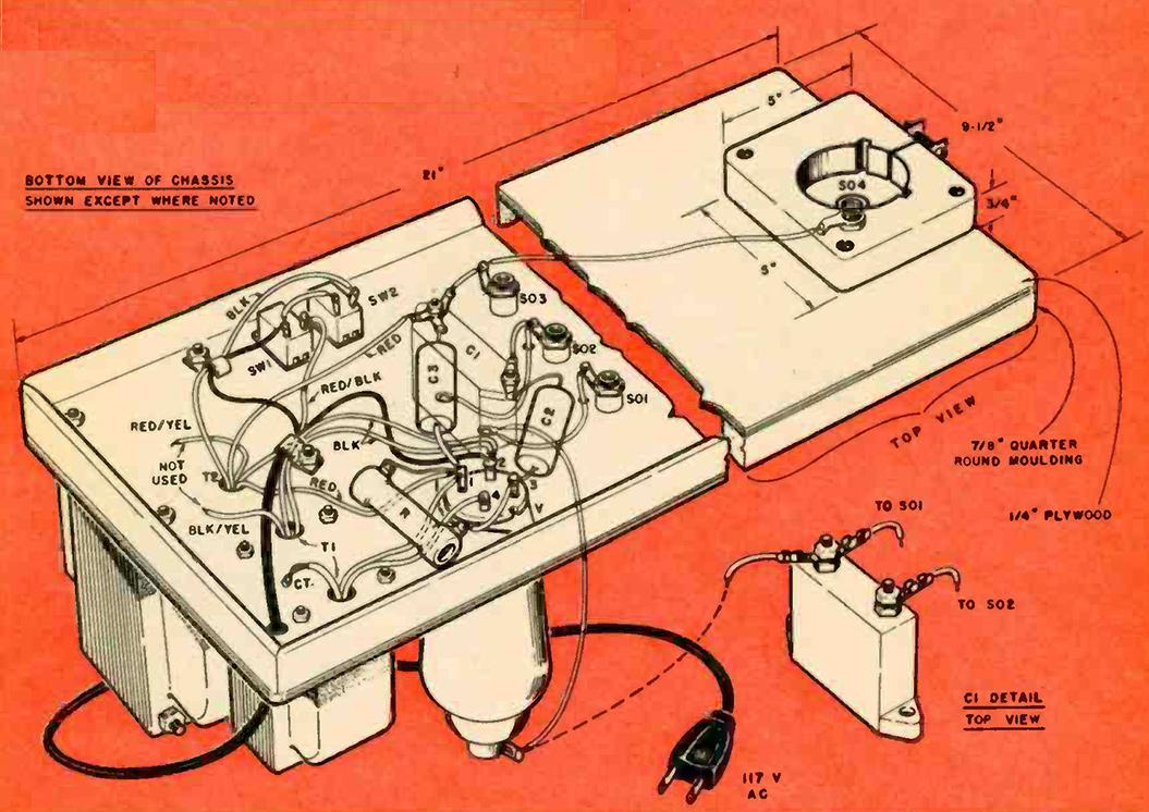
The primary coil can be started between varnish coats on the secondary. Cut 6 pieces of 3 inch wood dowels, each piece 7 inches long. Using a broad saw blade or the edge of a file, cut 40 shallow notches in each dowel along its length. Start the first notch 1 inch from one end, space the notches ½ inch apart so that 40 notches will occupy 5 inches all told.
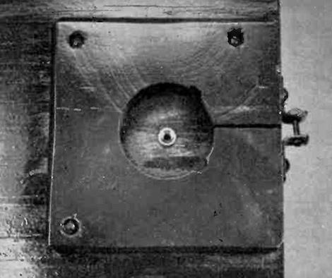
Next, cut two hexagons of either 3 ply, 4 inch pine or fir, (5½ inches from corner to opposite corner) or using ordinary tin shears, cut the hexagons from thin perforated Bakelite as was done in this model. Place the hexagons atop one another and drill a ¾ inch hole near each corner through each of the pieces. This will assure accurate alignment of the pairs of holes. While in this position, cut a 2½ inch diameter hole in each end plate to form the openings through which the secondary will pass. Finally, slip the dowels into the pairs of holes in the end plates flush with the surfaces and glue in place with a fast-drying cement. This makes up the "squirrel cage" form for the primary coil.
PARTS LIST
C1 - .0015 mfd 3,000 volt capacitor (Solar type XS)
C2 - .0005 mfd 10,000 volts paper tubular capacitor
C3 - .005 mfd 6,000 volt paper capacitor
R - 2,500 ohm 10 watt wire-wound resistor
V - 811A tube with 4-pin socket and plate cap
T1 - Filament transformer, primary 6.3 volts at 4 amps, center tap not used (Stancor P-4019)
T2 - Plate transformer, 117 volt primary, 750-0-750 at 265 ma, center tap not used (Stancor PC-8304)
SW1, SW2 - SPST toggle switches
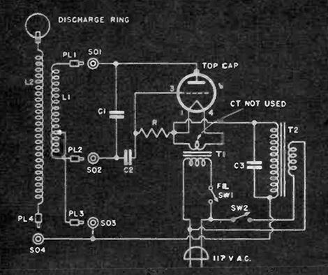
L1,L2 - See text
PL1-3, SO1-3 - Insulated banana plugs and sockets in three different colors
PL4, SO4 - Uninsulated banana plug and socket for secondary connection
Misc. - AC line cord and plug, wood base of 3 ply wood 1/4" thick 21" x 9 1/2" wood strips or molding for chassis apron, 5" x 5" x 3/4" wood block for two steel retainer clamping screw, forty-five inches of 3/8" wood dowel, one mailing or Bakelite tube 30" long by 2 diameter, two hexagons of wood or perforated Bakelite for primary cage, one binding post for top of secondary coil.
The primary is wound by fitting #16 Formvar enamelled wire into the dowel grooves and pulling tight around each turn, for a total of 39 turns. The ends of the coil may be wound once around the terminal dowel stick and crimped tightly in place.
Counting up from either end of the primary, scrape the Formvar or enamel insulation clean from the 15th turn. After scraping both ends of the winding, solder 20 inch lengths of flexibl wire to each end and to the tap at the 15th turn. This wire should have good insulation such as the vinyl material used on modern hookup wire. Connect a colored, insulated banana plug to the free end of each of the wires; use three different colors to match the banana jacks that will later be located on the oscillator chassis. The primary coil is now finished.
To protect the thin insulation of the secondary turns, cover the entire winding with one layer of a good grade of vinyl tape. This not only makes for long life but also for trim appearance. After the coils are in place and the leads plugged into their matching jacks, throw the filament switch on. The 811A tube filament should light. Turn the filament off. Using a 12 inch wood ruler or any scrap wood at least this long, place it under the bottom end plate of the primary and slide the coil up on the secondary until its top end plate is about 1/3 of the way from the upper end of the secondary. Turn on the filament for at least 10 seconds, then turn on the high-voltage switch. FROM THIS POINT ON, KEEP AWAY FROM THE COILS AND THE VACUUM TUBE. YOU ARE DEALING WITH 1500 VOLTS FROM THE TRANSFORMER AND MUST EXERCISE EXTREME CARE TO AVOID SHOCK.
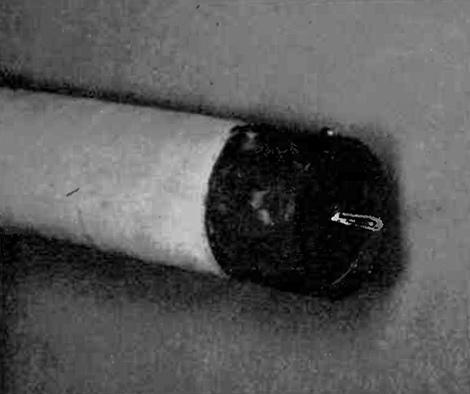
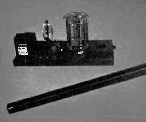
You may or may not get corona discharge from the wire ring in the upper binding post at this time (see photographs) since the secondary may not be in resonance. Let the primary slip slowly down the secondary column while you observe the ring. At a welldefined point along the column, corona sparks should begin to shoot from the ring. Note the position of the primary for maximum corona, TURN OFF THE PLATE SWITCH THEN THE FILAMENT SWITCH, and then mark the correct position of the primary coil with a bit of crayon on the vinyl tape. A heavy rubber band around this portion of the secondary will serve to hold the primary in place during use.
The Tesla coil is used principally as a demonstration of high-tension electricity. The corona discharge is fascinating to watch, especially in a dark room. Bring a long fluorescent tube, held in your hand, about two feet from the secondary and it will light brightly as if by magic; it will continue to glow up to four feet from the coil.
Stand three feet from the coil with a neon lamp in your mouth. You'll look like a human dynamo, because the lamp will glow brightly without connections.
Hold an insulated screwdriver in your hand and bring the blade within inches of the discharge ring. Sparks will leap to metal, but you will feel nothing.
Lay a piece of medium steel wool about the size of a golf ball on the discharge ring. When power is applied, you will see a startling display of St. Elmo's fire coming from the many strands.
Make a five-pointed star of aluminum foil and connect it to the discharge ring (vertically). Watch the streamers from the points and its spectacular effect.
If you can borrow some Geissler tubes filled with gases such as neon, helium, argon, mercury vapor, etc., hold one end of each of these in your hand in a fan-like arrangement. The display of colors will be startling, when they are brought near the discharge ring.
Carefully remove the secondary and, while it is still coaxial with the primary, lay the whole assembly on its side on a wood table top. Connect a length of wire to the banana plug at one end and another length to the binding post and form a 6 or 7 inch spark gap. (Some retuning by shifting the primary winding may be necessary since the secondary is now removed from ground.) REMEMBER THAT ADJUSTMENTS MUST BE MADE WITH BOTH SWITCHES OFF!
