
Nikola Tesla Articles
Advanced Spark Gap Technology
The Spark Gap: A Basic Definition
A spark gap in its simplest term is nothing more than an on and off switch. There are therefore, two electrical states or modes for the operation of a spark gap; infinite resistance, or non-conduction, and very low resistance, or conduction. In the state of conduction, a spark gap may be said to be "commutating" an electrical current. Fora given size and shape of spark gap, and depending on the surrounding environment of the gap, (gas, vacuum, magnetic field, etc.,) a certain voltage level (and in pulse circuits, a certain rise time of current value,) will be required to cause the spark gap to "spark," or conduct. Typically, voltages from as little as 1.2 KV to several hundreds of KV can be handled by a single spark gap. Currents from the microampere to the kiloampere range can likewise be switched. In pulse circuit applications, the shape of the spark gap plays a dominant role disproportionate to size in determining the commutation characteristics of the gap.
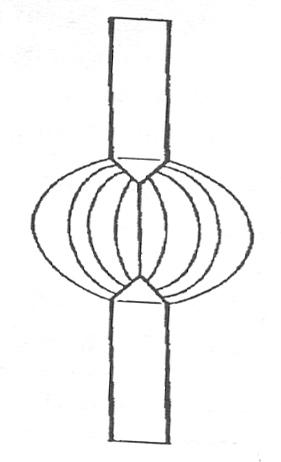
Several forms of spark gaps have been designed to act as voltage or current limiting devices. These are usually referred to as a "crowbar gap," "horn gap," or "safety gap." The horn gap is most widely used where it is desirable to limit the current dissipated in a voltage overstressed circuit. Another name given this form of gap is "Jacob's Ladder," as the behavior of an electric dischage or arc, begins at the bottom of the horn gap where the air spacing is small, then rises upward along the "v" shape of the gap until the spacing across the rods is so great, that the arc is self-extinguished. In this manner, the available power of the discharge is dissipated in the arc itself.
Evolution of the Spark Gap
The horn gap has been widely adapted to high voltage circuits in the electrical utility industry, since the early 1920's. The typical safety gap usually consists of a pair of polished metal spheres, where the diameter of the balls exceeds the air spacing of the gap between them. This relationship helps to maintain a uniform electric field in the vicinity of the gap. Sphere gaps as well as rod or "needle" gaps are the earliest forms of spark gaps to be used. The rod or pointed "needle" gap provides the least amount of ionization resistance or spark initiaton level, therefore this gap creates a spark at the lowest current and voltage levels; its electric field distribution being non-uniform, and highly concentrated in the vicinity of the points. Needle gaps were extensively used in conjunction with early electrostatic machines and later with induction coils.
With the advent of ever higher voltages being generated in research laboratories as of the late 1920's, multiple spark gaps, usually in the form of cascaded spheres, were developed to obtain the required "hold-off ' before spark gap break down. With the development of the Marx Impulse generator, the first forms of triggered sphere gaps were developed. The size and shape of some of these gaps were now also being utilized as large air capacitors. The first known forms of multiple parallel plate disc spark gaps evolved from a clear understanding of the need to maintain a very uniform electric field distribution across the entire gap apparatus. From these research efforts, pressurized spark gaps in various inert gases were developed. In each of these iterations, a common underlying problem that was encountered and needed to be eliminated, or at least controlled, was residual ionization in the vicinity of the gap. When a spark gap changes its electrical state from conduction (sparking,) to non-conduction, the space across the gap is said to be neutralized or "healed." This implies that there are no localized areas in the vicinity of the gap that are still partially ionized. Many factors can contribute to this problem of lingering ionization. Chief amoung these is the temperature of the metal surface area comprising the gap proper. Spark gap ionization will be discussed later in this paper.
The use of spark gaps in pulse circuits can be traced back to the time of Heinrich Hertz and his classical work on electromagnetic theory. When Nikola Tesla began experimenting with high frequency oscillators, he evolved a series of most unique and innovative electro-mechanical circuit interrupters or "breaks." These soon gave way to modified forms of the classical spark gap, as Tesla graduated from table-top size apparatus to higher powered equipment. Concurrent with the work of Tesla, other experimenters were to develop various forms of spark gaps, mostly for the development of wireless communication, using high powered oscillators as transmitters. Tesla, who pioneered the foundations of radio-frequency oscillators, progressed from mul-tiple-stage stationary gaps, to magnetic field gaps, to rotary gaps, to air-blast gaps, to hybrid combinations of these. With each iteration, Tesla realized the importance of maintaining control over oscillator pulse timing, duration, and repetition. These attributes are affected by the electrical and physical nature of the spark gap itself, as well as the environment in which it operates. In Tesla's efforts, as with others, oscillator circuit power levels increased; and it is generally thought that the evolution of spark gap technology progressed from the perennial stationary gap, to the non-synchronous rotary, the synchronous rotary, quenched stationary, quenched rotary, to pressurized hybrid gaps, some of which have been successfully carried over to present day use.
Classic Spark Gap Designs
The non-synchronous rotary gap, as the name implies, is a motor-driven gap with both rotating and stationary electrodes; the speed in revolutions per minute (RPM,) of the rotary electode assembly being some number that is not an even multiple of the operating frequency of the high voltage source that charges the oscillator circuit. In Tesla's work at Colorado Springs, a high speed non-synchronous rotary gap was used in conjunction with a double sphere gap. The rotary gap provided sufficient additional series resistance to the sphere gaps to keep the oscillator circuit from discharging at less than optimum charging voltage. Moreover, Tesla claimed to have achieved a commutation rate in excess of 4,000 with this arrangement. It should be noted here that there is virtually no documentation about Tesla's break used at Colorado Springs, other than a small paragraph and accompanying illustration as entered in his Diary Notes. Non-synchronous motors in a large variety of horsepower, RPM, frequency, and voltage ranges were most common and readily available; this in part accounts for their wide-spread use as a motive force in rotary gap circuits. An additional factor, important to most experimenters was the cost of each component; non-synchronous type motors being the most affordable. In wireless telegraphy work, a non-synchronous gap provided for higher power operation then a stationary gap, in the transmitter. However, this form of gap produced an uneven audible tone in the receiving circuit which was characterized as "harsh" and "jagged."
The synchronous rotary gap was primarily developed for high power wireless work. As its name implies, this form of gap has its rotary electrode assembly turning at an RPM speed that is a mathematical multiple of the high voltage charging circuit frequency. For instance, given an operational charging frequency of 60 Hz, and a motor speed of 3,600 RPM, there are two half-cycles per second and 60 revolutions per second, respectively. If there are 8 rotary electrodes, and each of these are made to commutate once per revolution, then the oscillatory pulse train will produce an amplitude envelope pulse repetition frequency (PRF) of 480 per second. In this example, where there is a direct one-to-one relationship for each full cycle of charging current and one full rotary disc revolution, the location for each rotary electrode around the periphery may be chosen to correspond to an exact point along the waveform. This is the chief advantage of the synchronous gap over their non-synchronous counterparts.
The use of a rotary gap that provides for precise timing of the charge/discharge cycling of the oscillator circuit, is imperative for maximum power transfer from the high voltage source into the oscillator itself. Moreover, a non-synchronous gap may represent a virtual short to the high voltage source on a periodic basis, wasting power, and providing fewer oscillatory wave-train pulses per unit of time; those that are successfully commutated, will be of widely varying peak amplitudes.
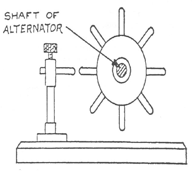
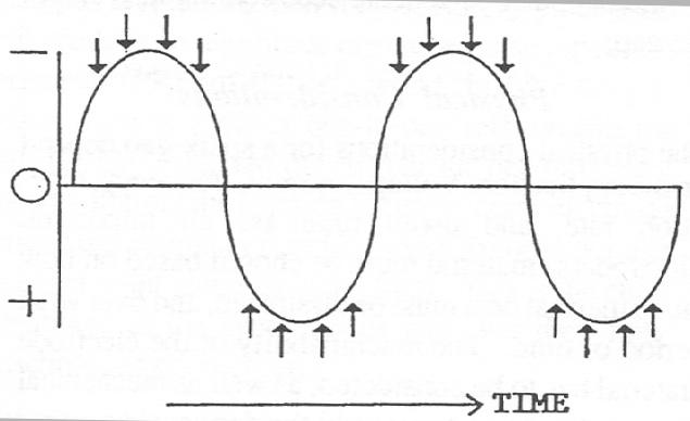
In high-powered wireless transmitters, the synchronous rotary gap, which produces a constant PRF, allows receiving circuits to demodulate the signal into a steady audio tone. This improvement in the wireless technique was the forerunner of true continuous wave transmission. Most often, a high frequency alternator (500Hz. typical,) was driven by a DC motor. The common driveshaft of this arrangement also provided for an extension, which mounted a large rotary gap assembly with up to about 50 rotary electrodes around the periphery of the rotating disc. The mechanical adjustment was set so that the gap would commutate on the 500 cycle sine-wave skirts only, and not at the peaks. Thus time was provided for the high voltage transformer to charge the oscillation capacitor, then discharge the stored energy into the Primary resonance circuit, without causing the power supply transformer to be shorted during the supply current sine-wave peaks.
When this form of gap is used for a Tesla Coil, maximum efficiency can be achieved. Each oscillatory wave-train is of a maximum peak amplitude, the high voltage power supply transformer does not reach maximum voltage at points in time when the gap is commutating, and the oscillator capacitor is allowed to reach a higher charge value before the gap commutates this stored energy into the Tesla Primary inductance. More RF current is transferred into the Tesla Secondary circuit.
It is known that for Tesla Coils where the mutual coupling co-efficient of the resonance transformer is very high (Q,) the duration of each primary oscillatory pulse must be limited (dwell time,) for maximum circuit efficiency. Both the non-synchronous and synchronous gaps, by virtue of their physical design, can be configured to provide pulse duration times down to the order of 20 microseconds. This is not easily accomplished; however it is practicable (typical rotary gap construction provides dwell times on the order of 100 microseconds.) Dwell time considerations for Tesla Coils will be covered in greater detail later in this paper.
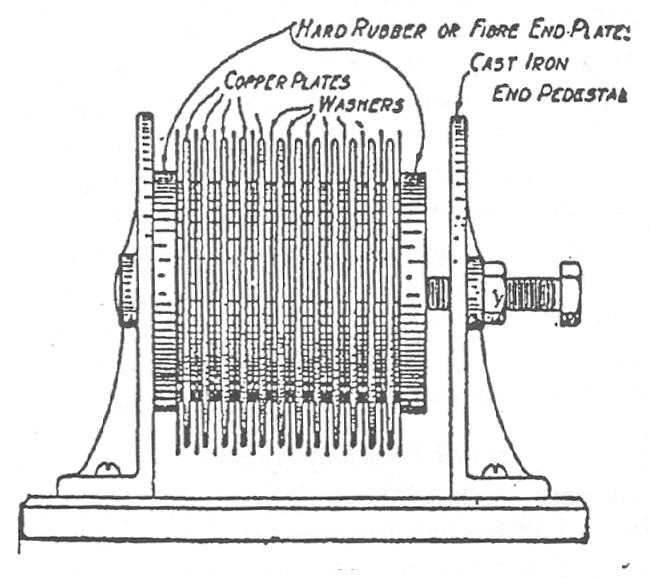
The continuing development and improvement of wireless transmission techniques in the early 1900's led to, amoung other things, a new form of spark discharger or commutator, the so-called "quenched gap." This device represented a radical departure from the previous forms of spark gaps. The first forms of these, became known as "semi-quenched" gaps, due to their electrode surfaces being exposed to air. The electrodes were of large surface area, often with serrated faces, and positioned parallel to each other with a very small gap space between. This type of gap was the first to create a more uniformly distributed electric field between the electrodes, but still relied on open air in the vicinity of the gap faces to serve as the dielectric agent. In high power apparatus, air proved to be too poor a dielectric for proper extinguishment of the arc ionization channel. The next generation that was developed, consisted of a series of these open air gaps arranged in a single physical assembly. Here, the electric field was evenly distributed to an even greater degree. As in the case of the multiple standard gap, since the air dielectric between each gap only had to contend with a small fraction of the total voltage applied, arc cut-off or quenching of the ionization process, was more readily accomplished.
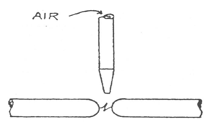
Each electrode element was either machined from a thick plate, or sometimes investment cast, usually with some form of heat radiating veins or fins, for cooling. In higher power units, the entire stack of electrodes were placed in an air chimney, with an external fan that forced cooling air across the whole assembly. Copper was most often used for electrode material, due to this metal's thermal co-efficient of heat transfer. The performance of this gap was still limited to the air dielectric performance characteristics in thegap spaces. It was known that gaseous combinations other than air, would provide additional quenching of the oscillatory spark discharge. Gap assemblies with sealed spark chambers were developed, and operated on the principal of converting normal air traped inside each chamber, into nitric oxide compounds. Nitrous oxide does not support ionization as much as air, and therefore provided superior quenching action. Here then, was a true quenched gap, possessing high power and commutation capability, compact size, and no external moving parts, (except for external cooling fans.) It was this type of gap that was widely adapted to wireless telegraphy work, and was used by the experimenter, commercial and military concerns alike. It had as its chief limitations, only moderate power handling capacity, and needed to be completely disassembled, thoroughly cleaned, reassembled, and conditioned, (converting the air in the individual spark chambers into nitric oxide,) on a very frequent basis.
Hybrid gap designs, based on quenched and rotary gap predecessors, were developed to handle very high power operating levels and long duty cycles. Parallel stacks of rotating discs, with notched radial veins, rotating in opposite directions, were placed in air tight chambers, and were pressurized with a noble gas, such as nitrogen, and more recently, sulpher hexiflouride. Other methods that have been developed in recent times for the control of post oscillatory discharge ionization include gaps operating in a partial vacuum, and the use of highly focused intense magnetic fields. Variations of these designs have also been adapted in the use of triggered gaps. In every case, the goal has been constant; extinguish the ionized path in the gap as quickly as possible, afterthe oscillatory pulse current has been commutated across the gap.
Physical Considerations
The physical considerations for a spark gap depend on the application. Voltage, current, frequency, repetition rate, and dwell time are all important. Electrode(s) material must be chosen based on how much thermal heat must be dissipated, and over what period of time. The machinability of the electrode material has to be considered, as well as mechanical strength (in rotary types) and the duty cycle or wear factor. In any case, the overall deciding factor should be the optimum design; spheres, rods, discs, concentric cyclinders, etc. Copper is an excellent material for its electrical conductivity and heat dissipation characteristics; oxygen-free hard copper, (OXFH) is often used. Early designs of stationary gaps routinely used zinc as electrode material. Thoriated tungsten has probably the best wear factor, but is extremely hard to machine; requiring diamond-faced machine tools and an extended length of of machining time; it is also the most costly for these reasons. Tungsten-carbide is slightly easier to machine, but does not last long, especially in high power applications. As previously mentioned, these attributes also carry over to the desired electrical characteristics. The shape of the electrodes determines to the greatest extent, the performance that can be expected. A gap surface that does not promote a uniform electric field distribution, will be prone to pre-discharge cycle ionization or "mis-firing." Material that becomes too hot, will promote localized gap space charge ionization; causing a deterioration in gap performance. A design that works well for a low powered circuit will not perform adequately at high power, even for brief operating periods. In pulse circuits (such as Tesla Coils,) dwell time of the gap commutation must be factored into the design.
Spark Gaps for Tesla Coils
Two sources of high voltage typically are used for energizing Tesla Coil high frequency oscillator circuits (Primary tank circuits.) These are direct current and alternating current. Tank circuits energized by direct current impose the highest possible duty cycle on a spark gap; the time constant for the appropriate level of capacitor charging, and the group delay time for dissipating that stored energy in the Tesla Primary inductance, as commutatable through the spark gap, being the only limiting factors. Therefore, if the high voltage direct current supply is one of very high availble current and load voltage, commutation rates or pulse repetition rates (PRF's) will likewise be extremely high. This imposes great stress on the heat dissipation capabilities of both the spark gap and the dielectric of the oscillation capacitor(s). In AC powered coils, care must be taken to insure that the points of gap commutation do not coincide with the current peaks of the charging current sinusoidal waveform; otherwise, the supply transformer will appear to be electrically shorted across the operating resistance of the gap, which can drop to 10 Ohms or less. When this occurs, excessive currentis drawn by the transformer, and may lead to premature failure, and power is wasted. In transformers that are current limited, this is not a problem. However, the Tesla Coil's performance will be severly limited.
Regardless of the source of high voltage, commutation dwell time must be carefully considered in the design of an efficient spark gap. Resonance transformers that are built with their primary and secondary windings in close physical relation to each other, will exhibit shorter pulsed energy transfer times between the two windings. This implies that after the oscillatory pulse from the capacitor has transferred into the Primary Coil, the spark gap must deionize very quickly, to prevent reverse EMF from transferring back through the gap into the capacitor. In this case, the Tesla Coil is said to have a high mutual coefficient of coupling, or high Q. Coil assemblies exhibiting a much longer energy transfer time are characterized as having a low Q, and in fact, imply a need for a longer commutation period or dwell time through the spark gap. Peak RF voltage that is sup-pe rim posed on a resonanant tank circuit may exceed twice the low frequency applied RMS charge voltage. Whereas this phenomena is well understood as it applies to the high voltage supply source and oscillation capacitor(s), too often the effects of this overvoltage are overlooked where the spark gap is concerned. Physical shape, spacing and choice of electrode material, all must be carefully selected, to accomodate this overvoltage condition. It is clear that if electrodes of small surface area are employed, the corresponding gap spacing must be greater than the case where large surfaced electrodes are deployed, and maintaining a uniform E-field distribution in the gap space becomes increasingly difficult.
Microscopic optical examination of spark gap electrodes that have been removed from service, reveal the problem of maintaining the sparking faces as uniform and smooth surfaces. In Tesla Coils of medium to high power, these surfaces show serious degradation; the impact of the spark discharge create deformities such as craters, the rims of which promote concentrated targets for subsequent discharge activity. This in turn, rapidly becomes a vicious circle, as the raised portions of metal become super heated, distorting the lines of the electric field and space charges in the gap. A term used to describe this tendency is "spark migration." Prevention of this condition is the single most important factor in any spark gap design and construction.
Arguably, the second and third most important design criteria for any Tesla Coil oscillation circuit spark gap is the commutation rate, or PRF, (pulse repitition frequency,) and duty cycle. The PRF should not be confused with the tank circuit oscillation frequency; they are entirely seperate.
However, a spark gap that is required to operate satisfactorally, say at 4,000 pulses per second, will have to be many times larger then a gap operating at 240 pps, even though in each example, the delivered energy in joules per pulse, as well as the tank circuit oscillator frequency are identical. The same can be stated for a Tesla Coil that is to be operated for an extended period of time; i.e., an energized state of several minutes, compared to an identical unit where the "on" time is only 5 seconds. Independent of these requirements but equally important, is the spark gap commutation dwell time, as previously noted.
Spark Gap Deployment
Spark gaps continue in use today because of their reliability, power handling capacity, functional simplicity, relative compact size, and the wide range of design applications to which they are most aptly suited. Many circuit designers and experimenters have endeavored to substitute semi-conductor devices for the function of a spark gap (with the attentive necessary additional circuit parameters, but accomplishing the same function.)
There are today, MOS-FET and similar devices that can be incorporated as switches in circuits where the operational voltage measures in the hundreds of volts, and the current in the hundreds of amps; and they do exhibit the ability of being controlled for dwell time with very short turn-on and turn-off times. However, in terms of peak and average power transfer capability, they pale in comparison to their spark gap counterparts. The timing circuitry required to control solid-state switches becomes complex and cumbersome. One other very important factor is cost; these devices and their ancillary components are fairly costly, and requires a sizable amount of space.
Vacuum tubes have been used for decades as electronic switches, but these too can only switch a finite amount of peak power, and the switch action controls only a constant amplitude sine wave, as compared to the spark gap, which can switch very complex wave forms and very high peak currents.
Trigger spark gaps have been recently developed that utilize a high intensity laser beam as the ionizing avalanche mechanism. Although very complex and costly, this approch does exhibit key advances in switch technology where currents on the order of megaamps need to be commutated into discharge tubes and other apparatus, and then sharply cut off in a dwell time of only nanoseconds. Here then, lies the leading edge in spark gap technology development. Whereas this kind of equipment is outside the grasp of most researchers and experimenters, the knowledge gained from the development of these advanced designs will have a future impact on spark gap technology in general.
