Nikola Tesla Articles
Bladeless Turbines
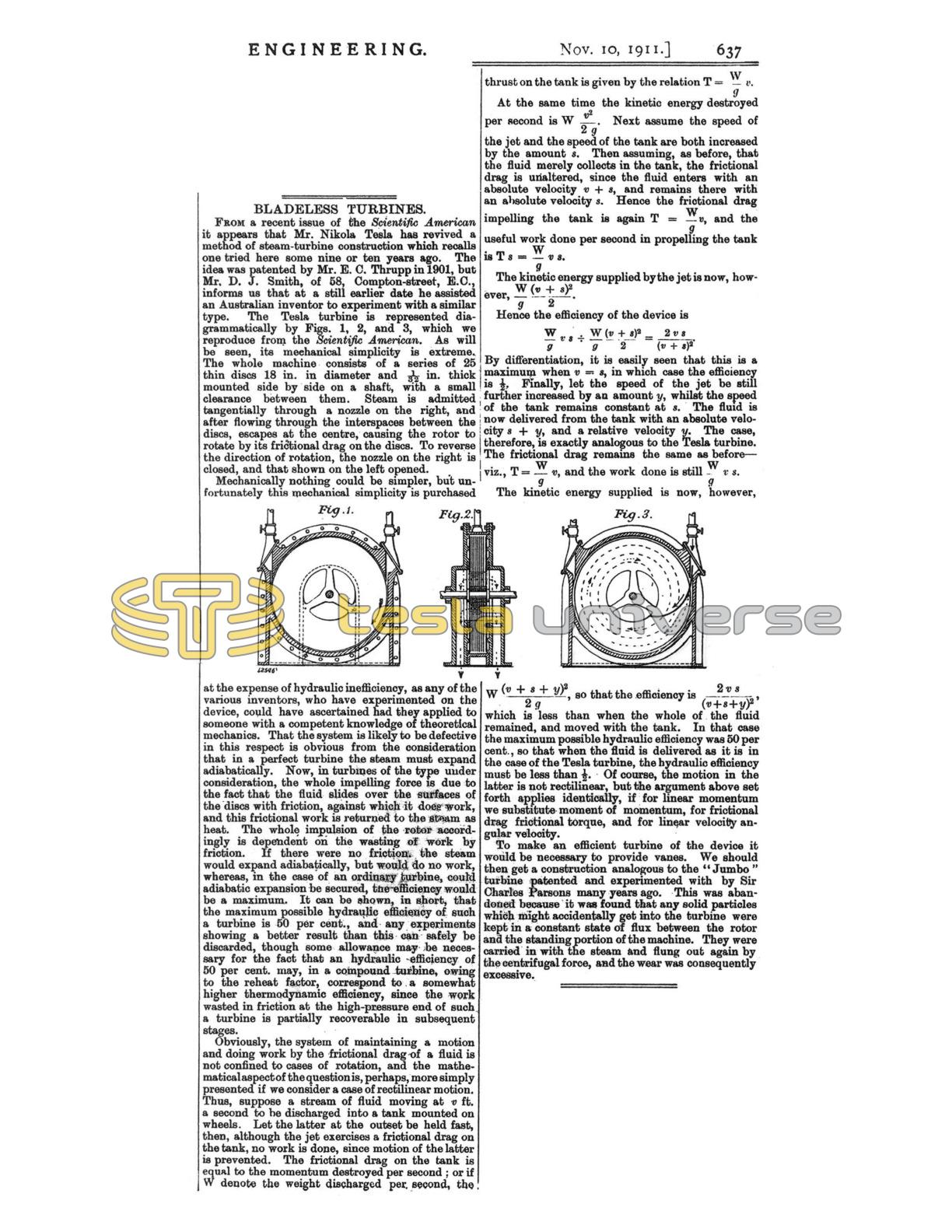
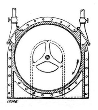
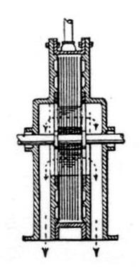
From a recent issue of the Scientific American it appears that Mr. Nikola Tesla has revived a method of steam-turbine construction which recalls one tried here some nine or ten years ago. The idea was patented by Mr. E. C. Thrupp in 1901, but Mr, D. J. Smith, of 58, Compton-street, E.C., informs us that at a still earlier date he assisted an Australian inventor to experiment with a similar type. The Tesla turbine is represented diagrammatically by Figs. 1, 2, and 3, which we reproduce from the Scientific American. As will be seen, its mechanical simplicity is extreme. The whole machine consists of a series of 25 thin discs 18 in. in diameter and 1/32 in. thick mounted side by side on a shaft, with a small clearance between them. Steam is admitted tangentially through a nozzle on the right, and after flowing through the interspaces between the discs, escapes at the centre, causing the rotor to rotate by its frictional drag on the discs. To reverse the direction of rotation, the nozzle on the right is closed, and that shown on the left opened.
Mechanically nothing could be simpler, but unfortunately this mechanical simplicity is purchased at the expense of hydraulic inefficiency, as any of the various inventors, who have experimented on the device, could have ascertained had they applied to someone with a competent knowledge of theoretical mechanics. That the system is likely to be defective in this respect is obvious from the consideration that in a perfect turbine the steam must expand adiabatically. Now, in turbines of the type under consideration, the whole impelling force is due to the fact that the fluid slides over the surfaces of the discs with friction, against which it does work, and this frictional work is returned to the steam as heat. The whole impulsion of the rotor accordingly is dependent on the wasting of work by friction. If there were no friction, the steam would expand adiabatically, but would do no work, whereas, in the case of an ordinary turbine, could adiabatic expansion be secured, the efficiency would be a maximum. It can be shown, in short, that the maximum possible hydraulic efficiency of such a turbine is 50 per cent., and any experiments showing a better result than this can safely be discarded, though some allowance may be necessary for the fact that an hydraulic efficiency of 50 per cent. may, in a compound turbine, owing to the reheat factor, correspond to a somewhat higher thermodynamic efficiency, since the work wasted in friction at the high-pressure end of such a turbine is partially recoverable in subsequent stages.
Obviously, the system of maintaining a motion and doing work by the frictional drag of a fluid is not confined to cases of rotation, and the mathematical aspect of the question is, perhaps, more simply presented if we consider a case of rectilinear motion. Thus, suppose a stream of fluid moving at v ft. a second to be discharged into a tank mounted on wheels. Let the latter at the outset be held fast, then, although the jet exercises a frictional drag on the tank, no work is done, since motion of the latter is prevented. The frictional drag on the tank is equal to the momentum destroyed per second; or if W denote the weight discharged per second, the thrust on the tank is given by the relation !$ T = \frac{W}{g} v !$.
At the same time the kinetic energy destroyed per second is !$ W \frac{v^2}{2 g} !$. Next assume the speed of the jet and the speed of the tank are both increased by the amount !$ s !$. Then assuming, as before, that the fluid merely collects in the tank, the frictional drag is unaltered, since the fluid enters with an absolute velocity !$ v + s !$, and remains there with an absolute velocity !$ s !$. Hence the frictional drag impelling the tank is again !$ T = \frac{W}{g} v !$, and the useful work done per second in propelling the tank is !$ T s = \frac{W}{g} v s !$.
The kinetic energy supplied by the jet is now, however, !$ \frac{W}{g} \frac{(v + s)^2}{2} !$.
Hence the efficiency of the device is
$$ \frac{W}{g} v s \div \frac{W}{g} \frac{(v+s)^2}{2} = \frac{2 v s}{(v + s)^2} $$.
By differentiation, it is easily seen that this is a maximum when !$ v = s !$, in which case the efficiency is 1/2. Finally, let the speed of the jet be still further increased by an amount !$ y !$, whilst the speed of the tank remains constant at !$ s !$. The fluid is now delivered from the tank with an absolute velocity !$ v \div s !$, and a relative velocity !$ y !$. The case, therefore, is exactly analogous to the Tesla turbine. The frictional drag remains the same as before - viz., !$ T = \frac{W}{g} v !$, and the work done is still !$ \frac{W}{g} v s !$.
The kinetic energy supplied is now, however, !$ W \frac{(v + s + y)^2}{2 g} !$, so that the efficiency is !$ \frac{2 v s}{(v + s + y)^2} !$, which is less than when the whole of the fluid remained, and moved with the tank. In that case the maximum possible hydraulic efficiency was 50 per cent., so that when the fluid is delivered as it is in the case of the Tesla turbine, the hydraulic efficiency must be less than ½. Of course, the motion in the latter is not rectilinear, but the argument above set forth applies identically, if for linear momentum we substitute moment of momentum, for frictional drag frictional torque, and for linear velocity angular velocity.
To make an efficient turbine of the device it would be necessary to provide vanes. We should then get a construction analogous to the "Jumbo" turbine patented and experimented with by Sir Charles Parsons many years ago. This was abandoned because it was found that any solid particles which might accidentally get into the turbine were kept in a constant state of flux between the rotor and the standing portion of the machine. They were carried in with the steam and flung out again by the centrifugal force, and the wear was consequently excessive.